Power line support
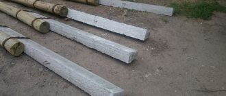
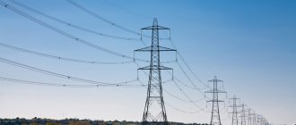
To transmit electricity over a distance, there is a need to install racks that support the wires of overhead lines at a certain distance from the ground and from each other. Reinforced concrete power transmission line supports are in great demand in our country. At least half of all electrical network support structures are made of this material.
Reinforced concrete power transmission line supports - classification by purpose
The classification of reinforced concrete supports by purpose does not go beyond the types of supports standardized in GOST and SNiP. Read in detail: Types of supports by purpose, but here I will briefly remind you.
Intermediate concrete supports are needed to support cables and wires. They are not subject to longitudinal or angular tension loads. (marking P10-3, P10-4)
Anchor concrete supports provide support for wires during their longitudinal tension. Anchor supports must be installed at the intersection of power lines with railways and other natural and engineering barriers.
Corner supports are placed at the turns of the power line route. At small angles (up to 30°), where the tension load is not large and if there is no change in the cross-section of the wires, angular intermediate supports (IP) are installed. At large rotation angles (more than 30°), corner anchor supports (CA) are installed. At the end of the power line, anchors, also known as end supports, are placed (A). For branches to subscribers, branch anchor supports (OA) are installed.
general description
The support is based on concrete, which is reinforced with an iron frame. Depending on the purpose, various cement compositions can be used. For example, maintenance of a 40-100 kV concrete tower power transmission line is carried out using structures made from centrifuged cement mortars.
The main advantages of reinforced concrete supports include resistance to corrosion, as well as to the action of chemical elements and substances contained in the air.
However, these designs also have certain disadvantages. To begin with, this is a significant weight, due to which work manipulations for their delivery and installation are also complicated. At the same time, reinforced concrete supports SV have significant sensitivity to mechanical damage. For example, during transportation these structures are often deformed - chips and cracks can be seen on the surface.
Device principle
The supports can be equipped with a steel frame, which is formed using metal reinforcement. Due to this, the structure receives high strength, as well as protection from aggressive environmental factors.
In this case, the fittings are used to fasten wires to crossbars or hooks. In the second option, supports are used, where the necessary holes for installing hooks are made at the factory.
It should be noted that equipping with functional elements can be done even before the installation of these structures in the required area has been completed. This feature distinguishes reinforced concrete supports from wooden ones, the equipment of which can only be done after installation.
Marking of concrete supports
It is worth focusing on the markings of the supports. In the previous paragraph I used the markings for the 10-2 supports. Let me explain how to read the markings of the supports. Reinforced concrete supports are marked as follows.
- The first two letters indicate the purpose of the support: P (intermediate) UP (intermediate corner), UA (corner anchor), A (anchor-end), OA (branch support), UOA (corner branch anchor).
- The second number means for which power transmission line the support is intended: the number “10” is a 10 kV power line.
- The third number after the dash is the standard size of the support. The number “1” is a 10.5 meter support, based on the SV-105 pillar. The number “2” is a support based on the SV-110 pillar. Detailed standard sizes are in the tables at the bottom of the article.
Cons of concrete lighting poles
- Considerable mass. These supports are heavier than metal structures that have the same applications. The large mass of reinforced concrete products makes loading, unloading and installation work difficult. Their transportation requires heavy-duty vehicles.
- Monotonous appearance. In this regard, metal supports stand out because they can be made in various styles, complemented with decorative elements, and painted in colors that match the overall design of the area.
- Weak resistance to sharp impacts.
Today, instead of heavy reinforced concrete supports, metal and modern composite products are used.
Installation of concrete supports
Calculation of supports is carried out by SNiP 2.02.01-83 and “Guide to the design of power lines and power line foundations...”. The calculation is based on deformation and bearing capacity.
To secure an intermediate support of type P10-3(4), you need to drill a cylindrical pit with a diameter of 35-40 cm, to a depth of 2000-25000 mm. An installation bolt is not needed for such a support.
Anchor corner and anchor branch supports are usually mounted with installation crossbars. Please note that the crossbars can be placed on the lower edge of the support and strut, buried in the ground and/or on the upper edge of the support, along the top of the pit. The crossbars provide additional stability to the support. The depth of installation of the support depends on the freezing of the soil. Usually 2000-2500 mm.
Features of power transmission lines
Reinforced concrete supports are considered the best solution for organizing support for high-voltage power lines. Wooden and iron analogs are also used for these purposes, but they have a number of significant limitations. But reinforced concrete structures also have restrictions on the loads on the electrical networks with which they have the ability to work.
At the same time, supports for power lines with an indicator of 15-1200 kV can be produced. In such a wide range, there are designs with different characteristics. The greater the applied voltage, the larger the size and weight of the traverses of the reinforced concrete support.
If power lines are located approximately at the same distance from the surface of the earth and the load on the supports is the same, then what determines the need to change the design parameters? This is quite logical taking into account the technological requirements, which are regulated by various regulations on the distances from the power transmission to the support and the ground surface, depending on the supplied current.
Grounding of concrete supports
Thanks to the design of the support posts, grounding the supports is very convenient. In the racks of SV supports, in the factory during their manufacture, metal reinforcement 10 mm in diameter is installed at the top and bottom of the rack. This reinforcement runs inextricably along the entire length of the rack. It is this reinforcement that serves to ground reinforced concrete supports.
Especially for the site “Electrics. Plumbing"
Tables of all types of concrete supports
©Elesant.ru
Other articles in the section: Overhead power lines
- Types of power transmission line supports by material
- Types of supports by purpose
- Overhead power lines with SIP wires
- Wooden supports for overhead power lines
- Reinforced concrete power transmission line supports
- Reinforced concrete power transmission line supports
- Power line support structures
- Tension of overhead power line wires
- SIP installation mistakes that should not be made
- Preparatory work for installation of overhead power lines
Carrying out repair work
Repair work on reinforced concrete supports to correct chips and cracks is carried out using polymer-cement compounds and paints and varnishes. Small surface cracks are treated with a layer of paint and varnish, and chips are covered with polymer-cement substances. In certain situations, supports can be reinforced with steel or reinforced concrete bands.
Wire repair includes: installation of new clamps, replacement of certain parts of garlands, arresters, pins, hooks, insulators, cable welding, etc. Most often, the installation process during repair is carried out in the same ways as when installing cables. Therefore, only the technology of work is described below, which is determined by the peculiarities of repairing high-voltage lines and installing them on live parts located in hard-to-reach places under voltage.
Cable replacement is usually carried out entirely in the anchor section. Due to the great complexity of this work, if there is a lack of time, the line can be connected to voltage, leaving the extended cable on the intermediate posts on the garlands, while it is temporarily connected to the loops of the anchor supports with special clamps. During subsequent shutdown, the cable is re-routed, clamps are installed and vibration dampers are installed. During a significant amount of work, the cable is replaced in phases. Transferring the cable to the clamps is often done without disconnecting the voltage.
Repair of individual areas
Repair of individual areas is carried out in different ways, they are determined by the scale of the deformation. When several wires break, a special coupling or bandage can be installed. If necessary, the damaged area is cut off and replaced with a new one.
Repair of the cable in the span is most often carried out without lowering it. The size of the insert must clearly fit the length of the cut part - otherwise misalignment of the hanging boom may occur. The insert wire must be of the same brand and have the same direction of turns as the one being replaced.
Before cutting the wire, mounting clamping wedges are inserted on both sides of the damaged area (on a cable with a cross-section of more than 350 mm2 - three) and the wire is tightened using winches, tightening nuts or pulleys. After tightening, cut off the damaged area and prepare an insert of the same size with allowance for fastening the connectors. Afterwards, the insert is connected to the area being replaced with connectors and the tightening device is released, thereby transferring the tension of the cable to the insert.
Wire repair work is most often carried out on disconnected power lines. If the repair is due to cutting the cable, then it must be grounded on both sides. If there is voltage, the area of the planned cut must first be bridged with a piece of cable, connecting it on both sides of the cut of the part of the wire being repaired.
Replacement of fittings and insulators is carried out, as a rule, by disconnecting the power line. On 30-120 kV supports disconnected from the kicking, replacement of solid garlands is carried out from a telescopic tower or from a traverse. While working from the traverse, the cable is pulled up with a winch in such a way that it is possible to freely disconnect the garland. A new one is installed in place of the damaged insulator.
When using the tower, it is placed under the garland, then the telescope is pulled out so that the mass of the cable is accepted by the basket and it can be disconnected. Transferring the mass of the wire to the telescope tower is permissible, taking into account the latter’s load capacity of more than 450 kg. When the maximum weight is exceeded, the tower is used only for ease of installation.
Replacing insulators
Replacement of insulators is carried out with preliminary unloading from the tension of the cable. For ease of work, a telescopic tower is used. A mounting clamp with a cord is attached to the cable, which is pulled using a winch through the installed block. After reducing the tension in the garland, the broken insulators in the latter are replaced. Replacement of large suspended structures is usually carried out by lowering the wires.
Replacing insulators without disconnecting the voltage is a labor-intensive task that requires special safety regulations. To carry out the work, various devices are used: insulating clamps and rods, as well as safety equipment - towers and platforms made of insulating material, as well as rotary cranes that are mounted on traverses.
Electricity distribution and transmission systems cover cities, villages and other facilities located in separate areas. In addition to transporting electricity over long distances, reinforced concrete poles are effectively used during the transmission of electricity from substations to consumers, as well as for arranging lighting for road surfaces and streets.
Additional installation recommendations
When the assembly of supports is carried out in a populated area, a double-pin head is used instead of the apical pin for double fastening of the wires. Whereas a four-pin traverse will replace a two-pin one. Additionally, if necessary, crossbars and support plates are installed.
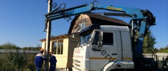
A single-column reinforced concrete support 110 kV is assembled starting with laying out the parts. Using a crane, the lower, middle and upper traverses are fixed to the rack. Then they begin to install the cable rack. After the support is assembled, it is pushed towards the pit using a crane or wooden rollers.
Properties of SV racks
The low price of a SV brand power transmission line support (rack) should alert the buyer. An important characteristic of power transmission line supports is the quality of their manufacture. It is very important to ensure that all technology standards are fully and accurately followed so that they can meet their stated capabilities. In addition, the use of materials of insufficient quality will lead to the rapid loss of the supports' performance qualities. They may sell you a support that will fall apart before installation begins.
One of the most important characteristics of SV racks is their resistance to external influences. First of all, it is worth noting their seismic resistance. They can withstand fluctuations up to 9 points.
It is also necessary that the stand, be it a reinforced concrete support or a wooden support, can withstand temperature conditions. Most supports tolerate low temperatures well, but if you plan to use them in extreme temperatures, you should definitely check their suitability for use in such an environment.
A correctly installed support of high quality production is capable of performing its functions for a long time and with the highest quality. If all standards are met, the service life of the supports will exceed 50 years. Installing supports is not the easiest task and therefore should only be done by professionals. In this case, you don’t have to worry about the quality of the work performed.
Buy supports (racks) SV
specializes in completing power transmission lines on the territory of the Russian Federation.
Here you can find only high quality products from the best manufacturers in the industry. We maintain affordable prices for all products sold and provide some of the best purchasing conditions. In our warehouse there are St. poles, the price of which depends on the terms of payment (prepayment or deferment). To order CB racks, contact our managers by phone. From us you can not only buy SV poles for power lines, but also order delivery by road from one of our two warehouses or by rail directly from the manufacturing plant.
