Online calculation of construction/reconstruction of overhead power lines (OHL)
Professional installation of power transmission line supports is a specialized area of activity.
A power line is a metal structure onto which wires carrying electric current are attached. There are intermediate supports, corner supports, anchor supports, end supports and special supports. This division is based on purpose, which is the main determining factor in the choice.
We provide services for the construction of power lines, installation of supports, and also carry out installation work. There are several types of technologies for the construction of power lines, so such work should only be carried out by professionals.
If you need prompt, safe installation of power line supports of any complexity, then we recommend contacting us today.
More photos here
“Installation of ASU. Increase in power by 190 kW"
190 kW More details
“Installation of MTP 40 kVA”
40 kW More details
Are your supports installed CORRECTLY?
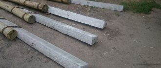
| We CORRECTLY install the following types of supports: wooden reinforced concrete (RC) metal composite (modular) | Installation cost: Reinforced concrete stand SV 95-3
*Supports are included in the price |
The final estimate is prepared on the basis of the agreed project, the customer’s technical specifications or a site visit, and the drawing up of a support diagram.
| Example of a support circuit | Estimate for installation of supports SV 95-3. Sheet 1 | Estimate for installation of supports SV 95-3. Sheet 2 | Estimate for installation of supports SV 95-3. Sheet 3 |
Stages of installation of power line towers
Even at the stage of preparatory work, the power line route is being laid: cleaning the route, leveling the ground and other work.
The route markings are carried out strictly in accordance with the project. When marking, the installation locations of the supports are noted, as well as their delivery to the installation sites. Depending on the design of the supports, they can be supplied disassembled or assembled. The disassembled supports are assembled near the installation site. The required traverses and other linear equipment are hung on the assembled support.
Before assembling the supports or in parallel with the assembly, pits or pits are dug to install the supports. The design of the pits and the dimensions of the pits are also specified in the project. For main power lines and overhead power lines, pits and pits are not dug manually. Drilling rigs are used for this.
Metal supports are placed on pre-made concrete foundations. Wooden supports and reinforced concrete supports for 0.4-6 kV power lines are installed without a foundation. To strengthen the stability of the support, a transverse console is placed at the end of the support in the ground (though not always). For 6-10 kV power lines, they are installed without a foundation, but with the surface of the support being poured with concrete. Power transmission line supports of 35-500 kV are installed with a cover at the end of the support dug into the ground (to strengthen the support) and pouring the support in the ground and the base of the support with concrete. Exceptions may be support trusses in the shape of the letter “P”.
a-Intermediate support; b- anchor support with a strut, placed at angles of rotation of power lines from 20 to 90 degrees. 10 Support, 5-strut (sub support)
The usual design of pits for wooden and concrete power transmission line supports up to 1 kV are cylindrical in shape, 1100-1500 mm deep and 100 mm wider in diameter than the size of the support. Such pits are made using drilling rigs.
Note: In cramped conditions, as well as with small volumes, a hole for support can be dug manually. The profile of the pit should not be cylindrical, but stepped.
Installation of lighting poles
Step-by-step installation of lighting poles
is carried out in accordance with the current standards of PUE (rules for the installation of electrical installations), ENiR (uniform norms and rules), TSN (territorial estimate standards).
More photos here
“Installation of a 160 kW transformer substation in New Moscow.”
149 kW More details
“Power supply for warehouse buildings. New technological connection to the networks of PJSC "MOESK"
200 kW More details
The standard procedure includes:
- marking on the section of the future route of the line;
- determination of installation locations for supports;
- drilling wells for constructing foundations for pillars;
- installation of the foundation substructure;
- installation of supports;
- installation of traverses;
- stretching the wires.
Data on the types of poles used, methods of their installation, the required set of special equipment, brand of wires and cables are included in the design documentation. The use of the project for the installation of lighting poles is permitted only after the document has been approved by the regulatory authorities.
Technology for installing supports using cranes
The technology for installing supports using the first three mechanisms is basically the same. The assembled support is laid along the axis of the overhead line. The center of gravity of the support is 1500 mm from the middle of the pit. The sling is attached to the support above its center of gravity. The second end of the sling is attached to the crane hook. The support rises. To hold it, retaining slings are attached to it along the length of the support. They are held by hands, if the support is small, or by transverse winches.
The raised support, sufficiently 20-30 cm from the ground, is directed into the pit and installed, securing the vertical position with temporary supports or guy wires.
Heavy rack supports (up to 25 meters weighing up to 7000 kg) are installed with a special installation machine, K-LEP-7.
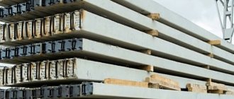
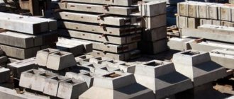
Types of reinforced concrete pillars
Structures for the construction of power lines, communications and lighting must be resistant to external factors. The main element of the product is a vibrating or centrifuged rack.
All types of products have markings, which are fixed by GOST. There are several types of classification of supports, which are based on the division into types:
- intermediate;
- anchor;
- branch;
- corner;
- transitional;
- transpositional;
- cross.
Based on the type of construction, multi-post and portal products are distinguished. Reinforced concrete pillars are used as load-bearing elements. Metal structures are designed for fastening equipment, suspensions, and various support parts.
The use of materials determines the conditions for using the products. An important production criterion is corrosion resistance, so the metal is coated with a special compound or galvanized.
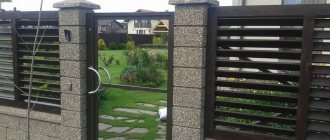
Pillar shapes
Precast concrete products for the installation of communications are manufactured at an industrial enterprise. The production technology provides for the use of special forms. Frame modules are used to install a Euro fence on a private property. Such products are made from metal and fiberglass.
Installation of supports by crane and tractor
Installation of supports using a crane and tractor has two options:
- Installation by stationary crane and tractor;
- Installation by tractor and crane on a wheeled base.
Installation by stationary crane and tractor
- The support is placed along the axis of the overhead line. Traction cables are attached to the bottom and top of the support;
- The lower cable is attached to the tractor winch. The crane stands at the pit and lifts the support above the ground. In this case, the tractor winch holds the bottom of the support. In this “suspended form” the support is lowered into the pit;
- The lower cable is detached from the tractor winch. Now the upper cable is attached to the winch, which begins to tighten;
- When the crane cable weakens, it is unfastened, and the support is held in place by the tractor and two side winches with temporary braces.
Installation by tractor and crane on wheel base
With this setup, things happen a little differently. The tractor is placed across the road, a meter from the pit. The support is laid along the route at a distance of 1500-2000 mm from the edge of the pit. The support is crushed by the crane and held in place by the tractor. Raising the support, its edge is installed in the pit. The tractor increases the tension of the support, while weakening the crane cable. When the entire load is transferred to the tractor, the crane is disconnected and moved to a safe distance. The final lifting of the support is done by a tractor.
Making pillars from concrete
The entire process of installing poles can be divided into several stages, each of which cannot be neglected, nor can the sequence of the technological process be disrupted. Typically, Finnish technology is used to install concrete pillar supports. It is considered the simplest, and a fence built using this technology lasts for many decades. Before installing supports, it is necessary to clear the planned perimeter of the site. It is important to remove large shrubs and small plants, as well as remove any debris that will interfere with the installation of the fence.
Site marking and formwork installation
In order to establish the boundaries of the future fence, it is necessary to install high pegs at the corners of the perimeter. A fishing line is stretched between them at a level of 1 meter from the ground. When the total length of the section is known, it will become clear how many supports are needed for the future fence. So, when laying with slate or corrugated board, the distance between the supports can reach 2 meters. The lightest fences, such as chain-link fencing, are recommended to be laid in increments of 3 meters. When planning a fence, it is necessary to take into account the parameters of the entrance group and gate.
In order to get a strong and reliable fence, you will need high-quality formwork. The box is made of plywood or edged boards. To prevent the concrete solution from spilling out of the formwork, it is necessary to cover it with polyethylene. This step will further strengthen the formwork, make it airtight and prevent possible deformation. All edges are fastened together with transverse strips. The formwork should be 40 centimeters below ground level. Usually the formwork is constructed on three sides. The fourth part is used for pouring concrete mortar.
It is recommended to assemble the formwork using screws. In this case, such a connection will allow you to quickly disassemble the formwork and subsequently use it on other construction sites.
Drilling holes
After the formwork construction stage, the stage of drilling holes for concrete fence posts follows. They should be slightly larger in size than the supports themselves. It is recommended to use hired equipment for drilling. This will reduce labor costs and the process will take much less time. In addition, if you dig wells with a shovel, you will have to dig wide trenches, which will subsequently need to be filled with concrete.
To prepare a concrete solution, you need to mix sand, crushed stone, water and cement. It is recommended to use a concrete mixer to prepare the solution. With this mixing method, it is recommended to first load crushed stone moistened with water, and then add the remaining ingredients. This will prevent sand and concrete mixture from sticking to the concrete mixer drum. Each installed pole must be measured vertically with a level.
For the best adhesion, the concrete solution should not be poured into the formwork, but should be regularly mixed inside the formwork.
Pouring concrete mortar and caring for it
It is recommended to fill each post at a time. It is not recommended to stop or interrupt the pouring process. When pouring, it is necessary to compact each layer of concrete solution and pierce it with a metal rod so that the air contained inside the mixture escapes and does not violate the integrity of the structure. Also, professional builders recommend mixing the concrete solution directly in the well. To do this, you can use a hammer drill using a special attachment.
It is estimated that it takes 7 days for partial drying. After these days, the formwork can be removed. This formwork can be installed on another construction site. The supports can be connected to each other with corrugated sheeting or chain-link mesh after four weeks. During this time, the concrete solution must be moistened with water and protected with polyethylene from the aggressive influence of the sun. It is believed that a properly cured concrete solution will be strong and stable.
Lifting the support manually
Of course, the only option left is to lift the supports manually. You can manually lift a wooden support for a 0.4 kV overhead line. The edge of the support is placed on the edge of the pit (pit), the cable is attached above the center of gravity of the support. When lifting the support, the support walkways are constantly rearranged from the top to the bottom of the support. The installed support is leveled, backfilled and compacted.
©Elesant.ru
Other articles in the section: Power lines
- Types of power transmission line supports by material
- Types of supports by purpose
- Overhead power lines with SIP wires
- Wooden supports for overhead power lines
- Reinforced concrete power transmission line supports
- Reinforced concrete power transmission line supports
- Power line support structures
- Tension of overhead power line wires
- SIP installation mistakes that should not be made
- Preparatory work for installation of overhead power lines
Options for intermediate supports of VLI
For the intermediate support of the subscriber outlet, it is reasonable to use a reinforced concrete support, grade SB 95-110. If such a support is made according to technology, it will last for many years. By design, SB brand poles have an internal grounding bus, and grounding taps are located at the top and bottom of the pole. This facilitates the installation of re-grounding of the VLI.
The intermediate pore is designed to support the VLI wire and does not experience stress from the tension of the wire. Therefore, the design of the intermediate support is single-post, that is, it is one post without supporting posts.
We sell reinforced concrete supports SV 95; SV 110 with delivery to the site and turnkey installation.
| Brand | Price for 1 piece. | Delivery from 1 to 25 pcs. | Installation |
| SV 95-2 | 5500 rub. | from 8000 rub. | from 12,000 rub. |
| SV 95-3 | 6500 rub. | from 8000 rub. | from 12,000 rub. |
| SV 110 | 8000 rub. | from 8000 rub. | from 12,000 rub. |
| Wooden post | 8000 rub. | from 8000 rub. | from 12,000 rub. |
You can find out the exact price from our operator by phone. +7 (495) 768-29-33
We also provide turnkey electrification. The engineer's visit is free!
Decoration options
After pouring the pillars and removing the formwork, you can move on to the design of the structure. Various materials are used for finishing. Reinforced concrete pillars can be primed, plastered, and faced with bricks and tiles.
Concrete structures used in the construction of fencing can be made in special formwork. It is possible to pour the concrete mixture while simultaneously laying stone along the walls of the formwork. In this case, in the finished column it will be necessary to design the joints between the masonry elements.
2.1. Preparatory work
Before starting work on drilling holes, assembling and installing supports, the following work must be completed:
— issuing a permit for excavation work and calling, in necessary cases (when carrying out work in the area of underground communications), the relevant representatives of interested organizations;
— laying out the communication line (with driving in pegs in places where holes are drilled for installing supports);
— preparation of reinforced concrete racks (cleaning the holes from cement mortar) and transporting them along the communication line route to the places of assembly and installation of supports;
— equipping the traverses with pins, insulators and struts (only for START type racks) and transporting them along the route to the places of assembly and installation of supports.
Number of reinforced concrete racks - 23 pcs.
The number of eight-pin traverses for the communication line with profile No. 2 is 46 pcs.
Rice. 1. Diagram of a communication line with 20 supports per 1 kilometer
Rice. 2. Profiles No. 2 and No. 3 for communication lines on reinforced concrete supports of the TU-45-USSR-79 type
Feedback on the work of the company BURMOSSTROY
Installation of poles in the Moscow region
- B
- Balashikha
- IN
- Vidnoe
- Volokolamsk
- Voskresensk
- D
- Dmitrov
- Domodedovo
- E
- Yegoryevsk
- Z
- Zaraysk
- AND
- Istra
- TO
- Kashira
- Wedge
- Kolomna
- Krasnogorsk
- L
- Lotoshino
- Lukhovitsy
- Lyubertsy
- M
- Mozhaisk
- Mytishchi
- N
- Noginsk
- Naro-Fominsk
- ABOUT
- Odintsovo
- Lakes
- Orekhovo-Zuevo
- P
- Pavlovsky Posad
- Podolsk
- Pushkino
- R
- Ramenskoye
- Ruza
- WITH
- Silver Ponds
- Sergiev Posad
- Serpukhov
- Solnechnogorsk
- Stupino
- T
- Taldom
- X
- Khimki
- H
- Chekhov
- Sh
- Shatura
- Shakhovskaya
- SCH
- Shchelkovo
Making your own posts
Features of the use of structures of this type allow you to create products of any configuration. Compliance with production technology in artisanal conditions ensures long service life. High-quality production is based on a strong reinforcing frame and pouring the concrete mixture without the formation of air bubbles.
A homemade pillar is made using the technology of pouring a foundation using formwork. Due to the underlying frame, this product is durable. The manufacturing process takes time. If the technology is violated, the pole may have defects.
The pillars can be erected at the installation site after preliminary preparation of the foundation. The advantages of this method are the reduction of material costs. In this case, the blocks must have high strength, and the masonry must be strictly vertical.
2.2. Drilling holes
It is recommended to drill holes for installing communication line supports using a drilling and crane machine type BM-202 (BM-302, BM-204).
Rice. 3. Drilling a hole for a single-post support
To drill a hole, the machine is installed in such a way that the center of its drill falls on the center of the future hole (on the alignment peg) and is secured with hydraulic jacks.
The depth of drilling the hole should be slightly greater (5 - 10 cm) than the depth of the support, which is 1.5 m for communication lines of classes I and II when installing supports 7.5 m long in hard soils with the number of wires on the support up to 24. X.
When drilling a hole, it is necessary to lay the excavated and discarded soil in an even roller so that around the hole there is a 15-20 m surface free of soil (Fig. 3).
Package of documents
To install and connect power line supports, the owner needs to collect the following documents:
- passport;
- document of ownership of the site;
- TIN;
- a list of electrical devices that will be constantly used by the owners (indicating the power);
- calculation of the network load;
- technical plan of the site indicating the nearest power transmission line supports and the proposed locations of new poles.
IMPORTANT! If there are communications (gas or pipelines, sewerage) on the ground near the future location of the supports, they must be displayed on the technical plan.
Types of power line supports
Based on the material, all power line supports are classified into:
- Wooden. The classic wood used for supports is pine. In the production of poles for lines with voltages up to 1000 V, other tree species are used, such as fir, oak, cedar, spruce. The advantages of wood in the production of power poles are low price and ease of manufacture;
- Metal ones are simple and reliable to use. Features of the operation of metal supports are labor-intensive installation and periodic coating with an anti-corrosion compound;
- Reinforced concrete ones do not depend on network voltage. Their use reduces costs since the structures do not require special care and periodic repairs. The strength of reinforced concrete depends on a combination of methods for its compaction.
Wooden supports are brought to the installation site disassembled, then assembled using bolts. Metal parts are transported in separate parts; after delivery to the work site, they are assembled and coated with an anti-corrosion compound. Installation of metal supports requires the construction of a foundation.
Send a request for installation of power lines