Overhead power transmission towers are an integral part of energy systems that are needed by all types of civil, military, and industrial facilities. In the complex of residential low-rise and high-rise construction, during the construction of industrial facilities, infrastructure is planned and built, which includes power lines, substations and supports. The durability of the power transmission line structure, its strength, and resistance to a number of external mechanical and natural factors depend on the choice of type and type of supports. Reliable supports, in turn, guarantee trouble-free power supply to infrastructure facilities, excluding interruptions and the occurrence of emergency situations. Modern standardized supports allow the construction of reliable overhead power lines in a short time in different climatic zones, on soils of different bearing capacity.
Types and purpose of power transmission line supports
All existing types of structural products that serve as supports perform the function of supporting overhead power line wires. Depending on the line voltage, there are supports designed for 220V, as well as 0.4, 6, 10, 35, 110, 150, 220, 330, 400, 500, 750 and 1150 kV. In this case, air lines are divided into three categories:
- from 0.4 to 10 kV;
- from 35 to 110 kV;
- from 220 to 330 kV.
The distance between the supporting elements of a power transmission line structure is called the span. The higher the operating voltage of a high-voltage line, the longer its crossarms, the larger the dimensions and weight of the structure.
In this case, the design of the support posts must provide the ability to install:
- cable terminations;
- protective switches and devices;
- panels and cabinets for connecting individual electrical receivers;
- switching and sectioning devices;
- street lighting fixtures of any design.
Based on the method of fastening, a distinction is made between supports that can be installed directly on the ground, as well as elements for the installation of which it is necessary to build a special foundation. The latter are divided into classic and narrowly basic. In its usual form, the width of the mounting base has an area of more than 4 m2, providing for frame, frame or poured foundations. The narrow base category includes all bases whose area is less than 4 m2. Often such fastenings involve the installation of a reinforced concrete or screw pile, a steel pipe and are used in areas with limited space.
Depending on the type of fastening, the supports can be differentiated into upright and guyed structures. The latter are the most stable and durable, requiring additional work on the installation of guys and their fastening, each of which must have its own separately formed foundation.
Installation of reinforced concrete supports
The first step to installing products is delivering them.
Stages of installing reinforced concrete pillars:
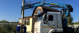
- Delivery is carried out by long special vehicles.
- The drilling and crane machine is brought to the installation site.
- After marking the site, drilling begins.
- A reinforced concrete electrical support is installed into the prepared pit using a crane.
- Fixation of the structure. A control check of its position is performed at the end of the process.
To determine how many poles are needed for proper installation, a calculation is made according to SNiP 2.02.01-83 and based on the document “Guide to the design of power lines and power line foundations.” It is carried out according to the possible deformation and load-bearing capacity of the pillar. The design and selection of supports must be made taking into account the purpose of the racks, the type of soil, the characteristics of the terrain and other important factors. It is important to know the weight of the electrical support, the depth and diameter of the hole into which the power line support will be installed.
The product can be loaded into a prepared pit using a crane.
The large dimensions of the structure do not allow them to be lifted by drilling machines, so cranes (SMK-10 and K-162 and other lifting mechanisms of appropriate lifting capacity) are used. After assembly, the pole is lifted by crane and lowered into the pit. The upper and lower crossbars are secured by digging a hole and laying it with a crane. It is secured to the pole with clamps. It is imperative to align the electrical support vertically and horizontally, and then backfill the pit. After installing the lighting poles, the serial number of the structure and the year of installation are indicated.
Metal, reinforced concrete, wood and composite supports - advantages and disadvantages
Depending on the material used, supports are made of:
- wood;
- reinforced concrete;
- become.
Currently, there are also composite type supports that include elements from various materials. For example, reinforced concrete can be assembled with metal tips, ribs, and posts to form the required configuration and size.
Each type of support elements has a set of individual characteristics that must be taken into account when designing and installing on site.
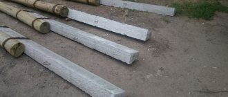
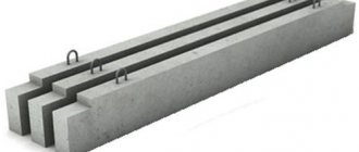
Reinforced concrete supports are made of concrete, which is reinforced with metal to enhance strength. In order to increase reliability for lines from 35 to 110 kV, centrifugation technology is used during production, with the help of which the concrete mixture is compacted as much as possible, eliminating air layers that reduce strength. During the production process, the solution is poured into special metal molds, inside of which there is a pre-created reinforced frame of transverse and longitudinal rods. Reinforced concrete products are resistant to external influences and corrosion. The chemical inertness of concrete does not allow it to interact with chemical elements, allowing operation in aggressive environments and reagents with which the air can be saturated. One of the main disadvantages of such supports is their high weight, which makes delivery difficult and places demands on the installation process and the quality of the prepared base. At the same time, reinforced concrete is characterized by a high degree of durability, which guarantees trouble-free operation of supports over a long service life, which is at least 60 - 80 years.
Wooden poles for power lines are made from solid logs. Most often, their use is relevant for low-voltage overhead lines with a voltage of 220 or 380 V. The material used in the production of supports is predominantly coniferous wood, less often deciduous. One of the main advantages of using wooden wire fastening elements is its affordable cost. in the presence of local types of wood, this allows for significant savings in the construction and laying of power lines. At the same time, such supports are inferior in durability to metal, reinforced concrete and composite products. During operation, wood is destroyed under the influence of sunlight, moisture, the parasitic influence of insects, due to seasonal temperature changes and other natural factors. In order to increase their service life, wooden logs are treated with special compounds. Mastics and resins can extend the durability of products to 20–25 years in the most favorable conditions. Wooden supports are used for the construction of A- and U-shaped structures.
Metal support products for power lines are made from steel alloys of established grades. Separate structural components, representing load-bearing elements and stiffeners in the form of beams and corners, are connected together. For this purpose, a welded rigid connection is used, which provides connection of surfaces at the molecular level or a prefabricated connection using bolts and nuts. In order to prevent a decrease in the strength of metal supports due to corrosion, galvanized rolled steel is often used. Some structures are painted with special protective compounds. Depending on the design features, the following types of steel supports are distinguished:
- lattice;
- multifaceted.
In addition, support structures made from closed and open profiles are distinguished. The former include hexagons and octahedrons, the latter triangles and products with a square section. Also, pipes are often used as a basis for the construction of steel supports for power lines.
Composite types of supporting elements are a new type of structures that incorporate individual units made of various materials.
Marking and designation
To designate power line supports, letter markings are used, which allows each structure to be assigned a separate name: For steel, composite and reinforced concrete types of supports designed for laying overhead lines with an operating voltage value from 35 to 330 kV, the following designations are accepted:
- “A” - anchor products;
- “US”, “U” and “AU” - designation of anchor-angle type products;
- “PS” and “P” are intermediate structures;
- “PUS” and “PU” - angular intermediate elements;
- “PVS” - intermediate supports with internal connections;
- “B” - reinforced concrete products (with the exception of supports designed for 500 kV);
- “KS” and “K” - end-type products;
- “PC” - composite intermediate support structures;
- "PP" - transitional intermediate products.
The digital index, which is given after the letter designation, reflects the voltage class. The presence of a letter indicator with the letter “t” indicates the presence of a cable stand with 2 cables. If the letter “p” is given, then the product provides for a change in the relative position of the conductors in the support structure. In most products, to achieve this goal, the wires are transferred to the adjacent tier, where the necessary sequence is formed.
The number indicated with a hyphen determines the number of circuits: if the value is odd, then the line is positioned as single-circuit, the even value belongs to multi-chain structures. In addition, the number may indicate the type of product. Additionally, some elements may indicate a digital value with a “+” sign, which reflects the height of the attachment to the base support. This value applies exclusively to supports made of steel.
Marking of concrete power poles for power lines
There are quite a lot of codes that are used in electrical grid construction. Electrical supports can be assembled at the enterprise in accordance with the construction project, additionally producing insulated suspension elements. Reinforced concrete products are marked as follows:
Each manufactured product is marked in a certain way.
- The letters indicate the direct purpose of installing the electrical support, for example, intermediate corner posts (IC) or branch supports (OA).
- The numerical value indicates a specific line of electrical components of the electrical network, for example, “10” is a 10 kV overhead line.
- The number indicated after the dash is the type and size of the pole. If the marking is “1”, then the vibrating stand SV-105 is 10.5 meters. The meaning of the number “2” is an electrical support based on the SV-110 pole.
Classification of supports by functional purpose
According to their design and technological purpose, power transmission line supports are divided into the following types:
- intermediate – the most popular and widely demanded type of product, which is designed to maintain conductors at the design height. When designing and building high-voltage lines, intermediate support elements make up 80–90% of the total number of products used. In this case, the intermediate supports are intended solely to support the wires and do not bear the load from the tension of the wires. The amount of permissible load depends on the model of the supporting elements, which are accepted for installation during individual calculations. Installation of intermediate supports is carried out on straight sections of the line. Steel and reinforced concrete products can be used at low temperatures of negative temperatures down to – 65 ºС, allowing the use of elements in the northern regions of the country;
- transitional or anchor - are used at points, network nodes, where the presence of barriers of natural origin or engineering structures requires a change in topology. These may include reservoirs, rivers, ravines, hills, infrastructure facilities, etc. The supports have increased dimensions, which allow them to withstand significant loads caused by the tension of the wires. The design of such products is characterized by increased rigidity;
- corner – products which are installed at the turning points of the high-voltage line. Angular intermediate elements are used for small rotation angles - up to 30 degrees. Above that, full-fledged corner anchor structures of supporting products are used, allowing them to withstand the forces of constant tension of wires and cables of adjacent spans;
- end - products, the installation of which is carried out at the starting and ending points according to the power line installation project. The wires from them go to the substation portals. Elements of this type, as a rule, perceive a one-sided load from the tension of the conductors;
- transpositional - supports of a special type, which are used if there is a need to organize branches or change the order of conductors running as part of an overhead line. Also, special products are used in cases where the line needs to be strengthened to increase the anti-wind load or when two or more cross power lines intersect.
Advantages of reinforced concrete supports
One of the most popular and in demand these days are reinforced concrete power line supports. Representing one of the most practical and cost-effective types for the construction of power lines, reinforced concrete structures have a number of advantages, including:
- long service life. The durability of reinforced concrete is 50-70 years, depending on operating conditions;
- resistance to external influences such as moisture, direct sunlight, etc.;
- environmentally friendly material that does not emit toxins and does not harm the environment;
- resistance to corrosion processes;
- high mechanical strength, which is achieved through concrete reinforcement;
- affordable price;
- minimum requirements for the installation and assembly process;
- wide operating temperature range - from -55 to + 55°C;
- high fire safety of a material that is not flammable;
Along with the advantages, reinforced concrete supports have only one drawback, which comes down to their large mass. Despite this, the use of products is justifiably considered cost-effective and effective for various networks and overhead lines that are designed to ensure trouble-free and uninterrupted power supply.
Disadvantages of prefabricated monolithic structures
Reasons for the formation of cracks
The use of prefabricated and prefabricated monolithic supports in comparison with massive monolithic ones allows to increase labor productivity, reduce concrete consumption and slightly reduce the cost of work. However, along with the undoubted advantages of prefabricated monolithic structures, disadvantages were also identified: the formation of cracks in supports, underutilization of the strength properties of concrete and the presence of “wet” processes during the construction of supports. The occurrence of cracks in monolithic and prefabricated monolithic bridge supports, as well as in other massive concrete and reinforced concrete structures, depends on an unfavorable combination of a large number of factors:
- fluctuations in ambient temperature;
- exothermic heating of concrete;
- freezing of free water in concrete;
- concrete shrinkage;
- combining elements with varying degrees of massiveness in one design;
- the use of concretes of different physical and mechanical properties for the shell and filler;
- chemical reactions between free alkali of cement stone and inert aggregates.
Types and technology of manufacturing reinforced concrete supports
Reinforced concrete foundations have a reinforced structure. For their manufacture, welded steel frames are used. During the manufacturing process, reinforced bars of both stressed and unstressed structures are placed in the workpieces. After this, the workpiece is filled with concrete mortar. Depending on the technological process used, supports are divided into the following categories:
- SV – vibrating racks for lines with voltage up to 35 kV, which are manufactured using the vibration compaction method, which is used to obtain a homogeneous structure of the material and eliminate air gaps;
- SK, SCP and STs are centrifuged racks designed for power lines with an operating voltage of more than 35 kV. During their manufacture, the mold with poured concrete is subject to rotation. The strength of centrifuged products makes it possible to reduce the cost of constructing overhead lines by increasing the distances between the installed supports.