03.06.2020
Equipment for tensioning reinforcing ropes is actively used in the construction of civil and industrial facilities.
Prestressing reinforced concrete structures increases their rigidity and resistance to cracking, and increases endurance when working under the influence of repeated loads. Prestressed structures and buildings are erected in seismic zones, and prestressing technology is used in the construction of facilities with increased safety and reliability factors.
Innovative methods of building construction used in frame construction are based on the technology of prestressing reinforced concrete structures during the construction process. Prestressed concrete structures are understood as reinforced concrete structures, the tension in which is created artificially during manufacturing by tensioning part or all of the working reinforcement to a given value.
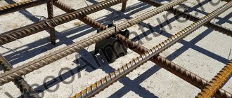
Construction includes installation of columns, their fixation and connection to prestressing cable reinforcement. The columns are fixed in a loaded state by tensioning the ropes, followed by concreting and releasing the ropes to form prestressed cells of the building frame. The use of this technology ensures increased load-bearing capacity of the building with minimal costs of reinforcement and concrete, on average saving up to 50%.
Why is prestressed reinforcement required?
The reinforcement in products can be non-tensioned or prestressed. The first type performs the function of passive reinforcement - it does not work until the slab bends from its own weight or from the influence of lateral load. Only at this moment will the lower reinforcing rods resist tension, but the concrete will already receive its share of tension and will react with a network of small cracks.
To avoid their appearance and increase the strength of the slab when exposed to bending loads, reinforcing structures are prestressed during the manufacture of concrete slabs. Reinforced concrete with stressed reinforcement is constantly in an active state.
The stress forces compressing the slab in the axial direction compensate for the operating forces caused by its own weight and load. Cracking practically does not occur in a stressed slab; it can withstand higher loads than an unstressed slab. In addition, the stressed slab is made thinner (140 mm instead of 170), which reduces concrete consumption.
Advantages of prestressing technology
- Increasing crack resistance, rigidity and load-bearing capacity of reinforced concrete structures;
- Increased water resistance of concrete, high corrosion resistance;
- Increasing the endurance and durability of the structure, resistance to dynamic loads;
- Increasing the seismic resistance of reinforced concrete structures;
- Reducing the thickness of floors or beams - increasing the usable area of the room;
- Reducing the number of expansion joints and increasing the size of the column grid;
- Reduced consumption of concrete and reinforcement;
- The ability to tension rope reinforcement of complex shapes, the ability to implement complex architectural projects.
Tension of prestressing reinforcement
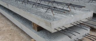
In the manufacture of slabs (road slabs, floor slabs, airfield slabs), a method called tension on stops is used. It consists in the fact that reinforcing bars, laid in a mold before pouring concrete, are subjected to tension. This is done in two ways:
- mechanical;
- electrothermal;
- combined, combining both of the previous ones.
In the mechanical method, the rods are anchored and stretched using hydraulic jacks. Concrete is poured into the mold, compacted and cured until it reaches 70% strength. Then the clamps are removed, and the tension force of the rods is transferred to the concrete through the anchors and corrugations. The product becomes a slab with prestressed reinforcement.
The electrothermal method involves passing a high current through the rods. From its action they heat up and lengthen along the axis. At this moment the concrete is poured. After it has set and hardened, the current is turned off, the rods cool, but the adhesion to the concrete prevents them from shortening, so the reinforcement is strained. In industry, the electrothermal method is more often used as it is simpler.
3. Tension in non-prestressing reinforcement
In non-prestressing reinforcement of prestressed elements, under the influence of joint deformations with concrete, initial compressive stresses arise: during compression of concrete, equal to losses from rapid creep: σs = σ6, and before loading the element, also equal to losses from shrinkage and creep of concrete: σs = σ6+ σ8+σ9.
For non-prestressed reinforcement located in the zone stretched during compression of the element, σs=σ8 is taken.
Concrete pre-compression force
The force of preliminary compression of concrete is taken equal to the resultant forces in prestressed and non-prestressed reinforcement
Р=σ sp А sp +σ` sp А` sp -σ s А s -σ` s А` s
and the eccentricity of this force relative to the center of gravity of the reduced section is determined from the condition of equality of the moments of the resultant and components (Fig. 2.2):
e op =( σ sp А sp y sp -σ` sp А` sp y ` sp -σ s А s y s +σ` s А` s y s )/ P
Figure - 2.2. Prestressed element a - distribution diagram of the compression force; b - diagram for determining the geometric characteristics of the reduced section; I—5 elementary figures; 6—9 fittings
Reduced section
To determine voltages
in sections of prestressed reinforced concrete elements in
stage I
before
area
of the reinforcement is replaced by the equivalent
cross-sectional
of concrete .
Based on the equality of deformations of reinforcement and concrete, the reduction is performed according to the ratio of the elastic moduli of the two materials
v = E s / E b .
The reduced cross-sectional area of the element will be:
A red
= A + vA sp + vA s + vA ` sp + vA ` s
where A is the cross-sectional area of the concrete minus the cross-sectional area of the channels and grooves.
Static moment of the reduced section relative to the /—/ axis passing along the lower edge of the section:
S red = ΣA i y i
where A i
— — area of part of the section;
y i
is the distance from the center of gravity
of the i -
th part of the section to the /-/ axis.
Distance from the center of gravity of the reduced section to the /—/ axis
y o
= S red / A red .
Moment of inertia of the reduced section relative to the axis passing through the center of gravity of the reduced section:
I red
= Σ(I i + A i (y 0 -y i ) 2 ),
where I i
is the moment of inertia
of the i
-th part of the section relative to the axis passing through the center of gravity of this part of the section.
The distance to the upper and lower boundaries of the core of the section from the center of gravity of the reduced section will be:
r=I red /A red
y 0 ; r inf =I red /(A red (hy 0 ))
6. The sequence of changes in prestresses in elements after loading with an external load
Centrally stretched elements
.
When manufacturing an element, the reinforcement is pulled to an initial controlled stress σcon on the stops of the molds, concreting is carried out, heat treated and kept in the mold until the concrete acquires the required transfer strength R bp .
In this state
1,
the first losses of σlos1 occurred in their main part (Fig. 2.3).
Then, when the molds are released from the stops and the tension of the reinforcement is released, due to the adhesion of the materials, compression of the concrete is created, rapid creep deformations develop and losses σ 6 -
state
2
.
Over time, second losses σl os 2 ,
Accordingly, elastic stresses in concrete decrease—state
3
.
The prestress in the reinforcement, taking into account total losses and elastic compression of concrete in this state, is equal to σ con – σ los1 – νσ bp
, here σlos1 – without losses σ3 and σ4, since the latter are taken into account in σcon.
Over time, second losses σlos2 occur, and elastic stresses in concrete decrease accordingly - state 3
.
Prestress in the reinforcement, taking into account total losses and elastic compression of concrete in this state, is equal to σ con – σ los – νσ bp1
After loading the element with a gradual increase in external load, the stress in concrete from preliminary compression is extinguished - state 4
.
The prestress in the reinforcement, taking into account losses at the level of zero stress in concrete in this state, is equal to σ sp =
σcon – σlos
A further increase in load leads to the appearance of limiting tensile stresses R btn
-
state
5
, i.e. the end of stage I of the stress-strain state.
Increment of stresses in tensile reinforcement after extinguishing compression in concrete based on the ultimate tensile strength of concrete εubt=2Rbtn/Eb and the compatibility of deformations of the two materials
σ s
= ε s E s = ε ubt E s = ( 2R btn /E b ) E s = 2v R btn .
The stress in prestressed tensile reinforcement before cracking is equal to σsp + 2 vR btn .
It exceeds the corresponding stress in elements without prestress by σsp
,
which increases the resistance to cracking. After the formation of cracks in stage II of the stress-strain state, the tensile force is perceived by the reinforcement. As the load increases, the cracks open. With a further increase in load, the stresses in the reinforcement become limiting and destruction occurs - stage III.
When tensioning reinforcement on concrete, the sequence of stress states is similar. The difference during the manufacturing period and before loading the element with an external load is that the initial controlled stress of the reinforcement is determined taking into account the compression of the concrete.
Bendable elements.
When tensioning the mold stops, the upper and lower reinforcement are pulled to the value of the initial controlled stresses σcon
,
σ`
sop
(Fig. 2.3).
They are usually assumed to be equal. After concreting and hardening during heat treatment, the bulk of the first losses of prestresses in the reinforcement occurs - state 1
.
After the concrete has acquired the required strength, the reinforcement is released from the mold stops and the concrete is compressed; preliminary stresses in the reinforcement as a result of rapid creep and elastic compression of concrete decrease - state 2
.
In this case, due to asymmetrical reinforcement A sp > A ` sp and
eccentric compression, the element receives a bend.
Over time, a second loss of reinforcement stress occurs σ los 2 -
state
3
.
After loading with an external load, the compression stresses in the concrete are extinguished - state 4
. Prestress in the reinforcement at the level of zero stress in concrete in the zone stretched under the action of an external load in this state
σsp =
σcon
-
σ
los
As the load increases, the stresses in the concrete of the tensile zone reach the limit R b t n
-
state
5
.
This will be the end of stage I of the stress-strain state during bending. At this stage, the stress in the reinforcement is σ sp + 2 vR btn .
In bending, as in tension, before the formation of cracks, the stress in the tensile reinforcement exceeds the corresponding stress in the reinforcement of elements without prestress by σ
sp .
This determines the significantly higher resistance to cracking during bending of prestressed elements.
As the load increases, cracks appear in the tensile zone, and stage II of the stress-strain state begins. With a further increase in load, the tensile stresses in the reinforcement and concrete reach their limit, and destruction occurs—stage III. Prestressed reinforcement with cross-sectional area A ` sp
located in a zone compressed by an external load is deformed together with the concrete of the compressed zone, while the preliminary tensile stresses in it decrease. At extreme compressive stresses in concrete, the stresses in the prestressing reinforcement in this zone
σsc=Rsc-σ`sp
The voltage σ`sp is determined with the tension accuracy factor γsp>1 and taking into account losses. For σ`sp < R sc
reinforcement with area
A sp
is compressed, and when σ`sp
> R sc
is stretched, and in this case the bearing capacity of the prestressed element is slightly reduced.
Figure 2.3 — Sequence of stress changes in a prestressed centrally tensioned element and a bending element
studfiles.net
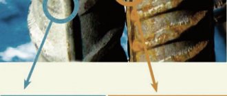
Anchoring of prestressed reinforcement
Anchoring or installation of anchor elements on rods is performed using:
- cold pressed washers;
- upset heads obtained by heating and flattening the ends of the rods;
- welded cylindrical shorts;
- wire spirals;
- inventory clips.
Requirements for prestressed reinforcement
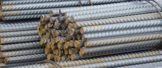
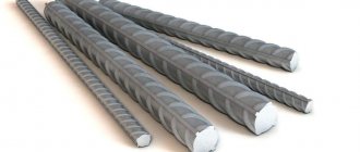
For the manufacture of prestressed reinforced concrete structures, special types of reinforcing steel are used that have high operating stress values (from 5000 to 7200 kgf/cm²). The list of these materials includes reinforcing steels:
- A600, A600S and At600S - 5400 kgf/cm²;
- A800 and At800 - 6000 kgf/cm²;
- A800 and At800 - 7200 kgf/cm² and others.
Steel classes for prestressed reinforcement are established by the regulatory documents according to which products are manufactured, in particular, GOST 25912-2015 and others. Calculation of stressed reinforcement is carried out during product design. Deviations of measured voltages from design values should not exceed 10%.
Reinforced concrete products with prestressed reinforcement are the main structural elements of airfields, multi-storey and high-rise buildings, and large-scale structures. For example, in our assortment any floor slabs are available for your choice.
Application in construction
Prestressed reinforced concrete is used in various fields of construction, making the following objects from it:
- high-rise towers, including television towers;
- large-span ceilings of industrial and residential buildings;
- tanks for treatment facilities;
- hydraulic structures, including dams, canals and locks;
- wide span bridges;
- columns and power poles;
- nuclear reactor buildings and fencing of nuclear power plants.
Retaining walls and enclosing panels are made from the same material. It is also suitable when it is necessary to strengthen the foundations of buildings and flights of stairs, buildings and premises located in seismic and explosive areas. And to further increase the strength of building frames and tunnels, prefabricated monolithic structures assembled from individual reinforced concrete elements are used.
An example of a bridge built using the technology of prestressing a reinforced concrete structure.
Products made from prestressed reinforced concrete are characterized by a large number of advantages, which allows them to be widely used in construction. And the shortcomings are mainly associated with insufficient workmanship, and can be compensated for by a responsible attitude to production. To avoid problems and get not only increased strength, but also a long service life, you should trust the creation of such reinforced concrete structures to professionals.