Types of connections between reinforcing elements
To construct a frame frame, different types of reinforcement connections are used. There are three main ways to join two reinforcing bars:
The overlapping reinforcement is joined as follows:
- using auxiliary parts: loops, paws, hooks. For A1-class fittings, only hooks and loops are used;
- overlap of reinforcing profile rods with straight ends;
- overlap of reinforcement with straight ends and transverse connection.
Mechanical joining of reinforcement (MSA) is classified as follows:
- pressed anchoring of reinforcement: the ends of the rods are connected inside a steel cylinder, which is crimped with a hydraulic press. As a result, the steel cuts between the ribs of the profile reinforcement
- threaded: made using a connecting cylinder with a cylindrical/conical thread cut inside. The corresponding thread is made at the ends of the connecting reinforcement bars;
- bolted: the reinforcement is connected by bolts screwed into the reinforcement body through the coupling wall;
- screw joining is made using a coupling, inside of which a thread identical to the profile of the reinforcement is cut and secured with locknuts.
Welded connection: The reinforcement is anchored using welding.
How to attach reinforcement to hardened concrete?
But these are all ways to obtain a sealing strength comparable to the release of reinforcement.
If you need less strength, then anchors will do just fine - they usually have comprehensive documentation for both pull-out force and shear.
There is only a nuance - if the release is made on anchors (mechanical, chemical - I don’t know whether there will be such an effect), then a new portion of concrete is poured along this release, and after that the full load is applied - the anchor may move a little in the hole before to the standard load, it will “wedge”, and accordingly a crack or gap will appear between the old concrete and the new one.
What should be the overlap of reinforcement for tying
Joining overlapping reinforcement using knitting is the easiest way to create a reliable metal frame. For this type of connection, popular A400 rods are used. The overlapping reinforcement is mechanically joined by knitting using wire. Two rods with straight ends are overlapped and tied with annealed wire. But there are certain requirements to ensure the strength of the connection.
When joining overlapping reinforcement using the knitting method, it is necessary to take into account the following parameters:
- the amount of reinforcement overlap;
- location of the connection in the frame and its purpose;
- relative position of overlap areas.
When reinforcing the foundation, it is unacceptable to install overlapping reinforcement in places of increased load (for example, corners of a building). Therefore, it is necessary to correctly calculate the areas for overlapping reinforcement bars when tying. They should be placed in those parts of the metal structure that bear the minimum load.
If for objective reasons this condition cannot be met, the length of the overlap of the rods will depend on the diameter of the reinforcement. For a strip foundation, the areas where the overlap of reinforcement is installed must be located in places not subject to stress and bending. If this condition is not met, the length of direct anchorage is taken to be equal to 90 diameters of the reinforcement being fastened. The dimensions of such connections are strictly regulated by GOSTs.
The overlap of the reinforcement during tying also depends on the following parameters:
- class of working fittings;
- brand of poured concrete;
- purpose of reinforced concrete foundation;
- degree of upcoming load.
You can find out the length of the regulated length of reinforcement anchorage from the standard table provided below.
Anchoring of reinforcement: table
Attention! Clause 8.3.27 of GOST 10922 2012 states that mechanical overlapping reinforcement connections are used for metal rods with a diameter of no more than 40 mm. Areas of the reinforced frame with maximum load are prohibited from being fixed using overlaps.
Overlapping reinforcement connection without welding when installing an armored belt
The amount of overlap of reinforcement during reinforcement is determined by a complex of factors. The diameter of the rods and the class of the poured concrete are also taken into account. The size of the overlap of the reinforcement when knitting can be calculated manually, but it is easier to navigate using the table.
Important! The length of the anchor when joining overlapping reinforcement also depends on the location of the reinforcing mesh: in the lower part of the slab (concrete tension zone), the overlap will be greater, and in the upper part of the slab (concrete compression zone) - less.
Length and features of its calculation
To correctly calculate the length of reinforcement, many indicators are taken into account. It is important to maintain the required value that will be embedded in reinforced concrete. Calculations are made with maximum accuracy. To determine the anchorage length, designers use graphs based on the stress in the bars and the class of the reinforcing elements.
Any specialist in the field of construction can work with schedules. The recommended length of the reinforcing bar is determined as follows:
- Determine the amount of stretching of the product along the abscissa axis.
- Lower the line to the desired grade of concrete.
- Find the point of intersection of the perpendicular from the abscissa axis with the resulting segment.
- Having designated the point Ra, draw a parallel to the ordinate axis.
- The resulting point will indicate the optimal length of the reinforcing bar.
The same technique is used to work with other charts. If it is impossible to maintain the recommended fastening length, it is necessary to equip the edges of the reinforcement with special elements. Such devices act as anchors. Fasteners are made in the form of plates, hooks and corners.
Fixation of reinforcing bars by electric welding
Butt jointing of reinforcing bars by welding is carried out only with reinforcement of classes A500C and A400C, because these grades relate to the materials being welded. The most common grade A400 cannot be joined by welding, since after heating it loses its anti-corrosion property and becomes less durable.
As Russian GOST 10922 and its replacement 14098 state, electric arc welding can be used for joining overlapping reinforcement with a diameter of less than 25 mm.
Attention! The length of the weld seam depends on the type of diameter of the reinforcing bar. For welding, electrodes with a cross section of 4 - 5 mm are used.
Drive in the reinforcement
Terrace on the 2nd floor, 1st residential floor. For the terrace you need to install a fence to attach the stand through the corner to the slab, because fencing at the edge of the slab, I think it is wrong to use an expansion anchor so that there are no spalls from the edge of the slab, but a chemical anchor - will they use it for the sake of several racks? I doubt. I’m thinking of driving in reinforcement with a diameter of 12 to a depth of 150mm. -And then the designer screamed that you can’t hammer it in, it ruins the concrete.
ARE THERE ANY STANDARDS PROHIBITED OR PERMITTED TO DRIVE REINFORCEMENT INTO CONCRETE (FLOORS, COATINGS).
Equipment for excavation of mine workings, POS, standard control, KR, AR
Offtop: I want to say right away that there are normal architects. At my institute, 2 architects do industrial buildings very well. Here, for example, a local genius worked. And in general, I have not yet encountered such lawlessness as here and often written on the forum.
That is, people, don't be impressed by one person and don't label the entire profession.
I have the impression that architects develop a sense of self-worth somewhere before entering college. At the institute they are simply explained that they are not like everyone else and it only intensifies a little. For skifff It’s always better to be softer with constructors. And with fantasies it’s tougher.
__________________ “There are no hopeless situations” Baron Munghausen
ARE THERE ANY STANDARDS PROHIBITED OR PERMITTED TO DRIVE REINFORCEMENT INTO CONCRETE (FLOORS, COATINGS).
I DIDN’T TOUCH HER, I DID NOT SPEAK ABOUT ANYTHING TO HER, SHE INVOLVED IN THE CONVERSATION. - WHERE IS IT SOFTER?
Equipment for excavation of mine workings, POS, standard control, KR, AR
There are no such requirements. Seek the truth, the truth is on your side. Before that I was joking
Also watch Kungfu Panda part 1. In particular, episode 26 min 25 sec. This is about you.
Requirements of regulatory documents for reinforcement connections
SNiP state that a concrete foundation must be reinforced with at least two reinforcement cages. For private construction, overlapping reinforcement joining methods are more often used, since this method is budget-friendly and more affordable, and does not require a hydraulic installation or a welding machine. To connect using this method, it is recommended to use reinforcement with a diameter of no more than 40 mm.
The distance between the rods , which are connected by overlap welding, must be more than 25 mm, which allows the concrete to penetrate into all narrow places in the structure. For rods with a diameter greater than 25 mm, a distance equal to the diameter of the reinforcement should be maintained.
The distance between the reinforcing rods along the width of the foundation should be no more than 8 sections of these rods. If the reinforcement is overlapped using knitting, then the distance between the rods is zero: it is determined only by the profile protrusions. The greatest distance in this case should be no more than 4 diameters of the reinforcing bars.
The distance between the joints themselves, located nearby, is taken to be 30 mm or more.
Expert advice
Experts recommend using pressed joining of reinforcement, rather than overlapping or screw couplings, if you need to connect rods with a cross-section larger than 25mm. These types of connections allow:
- increase the level of safety of the structure due to increased joint strength;
- reduce the cost of reinforcement, since the overlap method provides for up to 25% additional waste of reinforcement.
Indicators for calculation
To calculate the anchorage length of reinforcing elements as accurately as possible, the following data is taken into account:
- reinforcement section;
- profile type;
- brand of concrete;
- length of the structure and depth of laying of reinforcing elements;
- rod embedding method;
- tension at the coupling point.
The table allows you to quickly calculate the value. It may include different indicators. Similar tables are included in programs for calculating anchorage on a PC. The use of such techniques is acceptable for non-professional construction. In the professional sphere, this is how preliminary calculations are carried out. The final indicator is calculated using formulas.
To carry out calculations using formulas, you must have an engineering education and experience in the field of construction. Beginning builders can:
- use the services of specialized companies;
- determine the approximate value using tables, graphs and programs.
Considering the fact that the final result of construction and the strength of the structure depend on high-quality anchoring, it is recommended to order calculations from specialized companies.
It is better to pay for the work of specialists than to waste expensive building materials. Share:
Protective layer of concrete
The protective layer of concrete not only partially protects steel reinforcement from corrosion and temperature effects, but is also designed to ensure the joint operation of concrete and reinforcement.
1. For longitudinal reinforcement taken by calculation, the thickness of the protective layer must be ≥ d of the rod or rope and:
— ≥ 10 mm — in slabs and walls with a thickness of ≤ 100 mm;
- ≥ 15 mm - in slabs and walls with a thickness of > 100 mm, in ribs and beams with a height of < 250 mm;
— ≥ 20 mm — in ribs and beams ≥ 250 mm high, in columns;
— ≥ 30 mm — in foundation beams and prefabricated foundations;
— ≥ 35 mm — in monolithic foundations with concrete preparation;
— ≥ 70 mm — in monolithic foundations in the absence of concrete preparation;
2. For single-layer structures made of porous and lightweight concrete of classes B ≤ 7.5, the thickness of the protective layer is taken to be ≥ 20 mm, for external wall panels made without a textured layer - ≥ 25 mm. For single-layer aerated concrete structures, the thickness of the protective layer must be ≥ 25 mm in all cases.
3. For structural, transverse and distribution reinforcement, the protective layer of concrete is taken to be ≥ the diameter of the specified reinforcement and:
— ≥ 10 mm — with element section height < 250 mm;
— ≥ 10 mm — with a cross-sectional height of the element ≥ 250 mm;
For elements made of porous and lightweight concrete of classes B ≤ 7.5, regardless of the section height, as well as for elements made of cellular concrete, regardless of the class of concrete, the protective layer of transverse reinforcement is assumed to be ≥ 15 mm.
4. To ensure free placement of solid reinforcing bars, frames or meshes into the form (formwork), running along the entire length or width of the product, the dimensions of the rods, frames or meshes are taken smaller than the dimensions of the form: by 20 mm (10 mm on each side = Δlк) - for element length ≤ 9 m, by 30 mm (15 mm on each side) - for element length ≤ 12 m - by 15 mm, by 20 mm - for element length >12 m.
5. In hollow elements of a box-shaped or annular section, the distance from the inner surface of the concrete to the longitudinal reinforcement rods is taken according to clauses 1 and 3.
But that's not all. In reinforced concrete elements working in bending or tension, cracks form in the tensile zone of the section, and in order for the reinforcement to work together with the concrete, its ends must be securely clamped in areas without cracks. However, anchoring of the reinforcement can be achieved in another way.
how to make a hole in concrete to drive 16 reinforcement
It means a lot to me: through the load-bearing wall, part of the load from the foundation slabs is redistributed to the floors. And vice versa. In fact, frost heaving (for example) tries to break not one foundation slab, but 3 (+ 2 floors) at once. This makes it possible to make the foundation very thin, but at the same time very strong.
What will this give Dron - I don’t know - he’s hiding his project from me 
These are still all compression loads and not tensile or fracture loads. So the redistribution of loads will work without a vertical thread. The masonry itself or the blocks, set with glue or mortar, form a monolith that is firmly connected to the bottom slab and the ceiling of the second floor. And frost heaving will be redistributed exactly the same
You are mistaken: suppose one corner of the foundation slab went up, it (the slab) began to bend, if there is just block material on the slab, then it will not help in any way - the glue will come off, the bricks will crack (already counted) - the masonry does not work in tension (axiom).
But if it’s my wall, then through vertical reinforcement the wall pulled the central part of the foundation along with it, partially transferring the load to the floor. My house simply tilts at one angle without losing its geometry.
An example for understanding: a sheet of cardboard and a cardboard box (like a shoe box): lifting the sheet by the corner, you will simply bend it (if it is large and heavy enough), and a box glued together from the same sheet calmly holds the weight of a person (by ribs), and you certainly won’t change its geometry by lifting it by one of the corners.
In the last article, I told you that I had a shallow foundation poured for my bath house. In the process of work, it turned out that my brave monolithics instead of knitting reinforcement. They simply welded it using electrode welding.
Photo by the author. The fittings are welded. Photo by the author. The fittings are welded.
To my question to the foreman, why don’t you knit the reinforcement? I received the answer: “ There is no big difference between how we tie the reinforcement, welding or knitting. Both methods handle the load perfectly. Especially in low-rise construction.”
But naturally, when you start building, you study some of the stages of building a house. The following ideas about a strip foundation formed in my head:
- Non-reinforced concrete copes well with compressive loads. But it practically does not work in tension. Therefore, when reinforcement is placed in concrete, this product acquires a new property - good tensile resistance due to the reinforcement.
- The purpose of the reinforcement is to prevent concrete from collapsing due to tensile load.
- Accordingly, iron reinforcement is produced of a certain grade, which resists tensile loads well. So as not to disturb the structure of the metal due to temperature loads. Metal must be knitted with wire.
Builders Zh.B. The bridge's reinforcement is knitted. Builders Zh.B. The bridge's reinforcement is knitted.
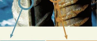
- With artisanal electrode welding, the body of the reinforcement is burned. The working cross-section is reduced. In addition, the strength of the steel decreases due to overheating of the joint. Which leads to increased stretching at the welding site.
It is worth noting that reinforcement can be welded; there is even a specialty: “reinforcement welder.” But under certain conditions:
- The brand of fittings must correspond to this operation. You cannot take any kind of fittings and cook them with any electrodes.
- When working in workshops and concrete factories, resistance welding is used. Since this welding involves controlled heating of the reinforcement rod. Which does not affect the strength of the structure.
- According to SNiPs, it is possible to weld reinforcement, but with certain electrodes and a certain method. And you should use a certain brand of fittings.
Therefore, the conclusion is this: So as not to cause harm during low-rise construction. So as not to weaken the monolithic foundation structure. The reinforcement should only be knitted with wire. And leave welding in those places where there is a design and each stage of construction is planned and calculated by engineers.
This is the fifth article in this series. Next, I will tell you what construction material I chose, how the shallow foundation was poured, why the wall cracked and how the roof was raised, and many other solutions. Not quite right. Learn from my mistakes. Don't let yours in. Subscribe. Articles are published every day at 8 am Moscow time. You can also click on the tag below “Timothy’s House of Baths”.
Concreting stages
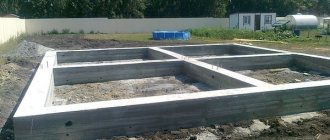
Marking the site is one of the first stages that should precede the main work.
If we look at the example of site arrangement, then initially it is necessary to select and clear the area, limit it with formwork, having previously marked the perimeter with a stretched rope. The top layer of soil is removed 25 cm deep. Identified communications are protected by a pipe or box. The soil is leveled and compacted. Further work is carried out in the following sequence:
- preparatory actions;
- reinforcement;
- installation of beacons;
- pouring concrete mixture.
Preparation
It includes:
- installation of formwork;
- creation of a moisture-proofing layer;
- pillow formation.
After formwork is formed, the preparatory pad is lined with crushed stone.
The formwork is made from wooden boards, using pegs and spacers as fastenings. The position of the elements is measured by the level. The mixture is then poured along the upper edge of the formwork. Geotextiles are a moisture-resistant material. A cheap option is polyethylene. They cover the bottom to prevent the absorption of moisture from the concrete solution into the soil. To form a cushion, wet sand is poured and compacted, the surface is leveled and crushed stone of a small or medium fraction up to 6-8 cm high is laid on top, also compacting.
Reinforcement
The rods of the selected material and cross-section are laid in the form of a lattice, forming a frame plane. The joining points (crosses) are fixed with metal wire. First you need to calculate the number of rods according to the area and the step between them. If the site under construction is not intended for heavy loads, then wire mesh is suitable for reinforcement. It's cheaper.
The metal frame should be assembled like a lattice.
Craftsmen do not recommend welding intersection points. This will make the frame rigid and deprive it of mobility, which threatens the formation of cracks in the future.
Guide beacons
They are cement slides of equal height located in rows with a UD profile on the tops. The composition proportions are cement/sand -1:4. Slides define the upper level of the site; their installation allows you to fill a flat surface. Between the pins inserted along the perimeter of the site, intersecting threads are pulled parallel to the edges of the formwork. Slides are placed at intersections. A horizontal level is required for work. The step between the beacons is 0.5-1 m. You can start concreting after they have completely hardened, otherwise the guides will shift.
Concreting
Preparing the mixture
The mixing of the material must be carried out taking into account the proportional ratio of its components.
Kneading yourself requires adherence to technology and proportions. On average, cement/sand/crushed stone is taken in a ratio of 1:3:1. For 1 bucket of cement there are 2 buckets of water. It is better to use a concrete mixer. After pouring water, cement, crushed stone and sand are successively poured into a rotating container, continuing to knead for 20 minutes. The components can be calculated using special tables depending on the type of concrete. The cement used is M400 grade. The table gives a brief idea of the proportions:
| Concrete grade, M | Cement/sand/crushed stone ratio, kg | Volume of concrete obtained from 10 liters of cement, l |
| 100 | 1:4,6:7 | 78 |
| 200 | 1:2,8:4,8 | 54 |
| 300 | 1:1,9:3,7 | 41 |
| 400 | 1:1,2:2,7 | 31 |
Pouring concrete
Concrete embedding of reinforcement occurs by uniformly distributing the solution with a shovel between the beacons. The mixture should rise slightly above the slides. Alignment is carried out using a rod or a special device - a rule, installing it between the beacons and pulling it back and forth. If necessary, the manipulation is repeated. To prevent cracking of concrete, the poured area must be covered with film to prevent rapid drying. Irregularities and defects are smoothed out with a spatula after setting.