| PUBLIC JOINT STOCK COMPANY "RUSSIAN NETWORKS" | |
| 0 | PERFORMANCE STANDARD |
| PJSC "ROSSETI" | |
| STO 34.01-2.2-026-2017 | |
Organization standard
Date of introduction: 10/27/2017
PJSC Rosseti
The goals and principles of standardization in the Russian Federation are established by the Federal Law of December 27, 2002 No. 184-FZ “On Technical Regulation”, objects of standardization and general provisions in the development and application of standards of organizations of the Russian Federation - GOST R 1.4-2004 “Standardization in the Russian Federation. Organization standards. General provisions", general requirements for the construction, presentation, design, content and designation of interstate standards, rules and recommendations for interstate standardization and amendments to them - GOST 1.5-2001, rules for construction, presentation, design and designation of national standards of the Russian Federation, general requirements to their content, as well as the rules for the design and presentation of changes to the national standards of the Russian Federation - GOST R 1.5-2012.
1. DEVELOPED:
Public Joint Stock Company "Federal Test Center"
2. INTRODUCED:
Department of Technological Development and Innovation and Department for Work with Equipment Manufacturers of PJSC Rosseti
3. APPROVED AND PUT INTO EFFECT:
By Order of PJSC Rosseti dated October 27, 2017 No. 590r
4. INTRODUCED FOR THE FIRST TIME.
Comments and suggestions on normative and technical documentation should be sent to Rosseti PJSC according to the contacts indicated on the official information resource, or by email to the address: [email protected] This document cannot be fully or partially reproduced, replicated and distributed as an official publication without permission from PJSC Rosseti. This restriction does not provide for a ban on third-party organizations joining this standard and using it in their production and economic activities. In case of accession to the standard of a third party, it is necessary to notify PJSC Rosseti.
2
| № p/p | Name of functional indicators | Requirement in accordance with regulatory documentation (STO, GOST, SNiP) | Regulatory document |
| hard-to-clean (including oily) antiseptics, subject to confirmation of the service life and requirements for fire resistance and safety (environmental friendliness) of the use of support posts. | |||
| 1.5.2. | Ratio of antiseptic components | Elemsept A-60 (A-30) CuO - 11.4±2x(5.7±1.5) CrO3 -28.5±2x(14.25±1.5) As205 -20.1±2x(10.05±1.5) KhMF BF (1 - 20%) Mass fraction in 1% solution K(Na)2Cr207x2-H20 - 0.43 CuS04x5-H20 -0.22 NaF -0.1 NH4F/HF ± NH4F -0.25 KMF 221 (1 - 20%) Mass fraction in 1% solution K(Na)2Cr207x2-H20 - 0.4 CuSO4x5-H20 -0.4 NaF - 0.2 CP (1 - 30%) Mass fraction in 1% solution Cr(VI) in terms of K(Na)2Cr207x2-H20 - from 0.5 to 0.44 Cu(H) in terms of CuS04x5-H20 - from 0.33 to 0.28 F in terms of NaF - from 0.17 to 0.28 ХМ 11 (1-20%) Mass fraction in 1% solution of K(Na)2Cr207x2-H20 - 0.5 CuSO4x5-H20 -0.5 | GOST 28815-96, clause 3.3 GOST 23787.9-84, clause 1.4 |
11
| № p/p | Name of functional indicators | Requirement in accordance with regulatory documentation (STO, GOST, SNiP) | Regulatory document |
| XM 32 (grades 1 and 2) Mass fraction in 1% solution: K(Na)2Cr207x2-H20 - 0.6 CuS04x5-H20 -0.4 * when using other antiseptics - in accordance with the manufacturer's specifications | |||
| 1.5.3. | Impregnation method | in a high-pressure autoclave using the “vacuum-pressure-vacuum” method. It is allowed to carry out the process of accelerated fixation of antiseptic components in wood for the winter period. | GOST 20022.6-93 |
| 1.5.4. | Wood moisture content before impregnation, no more than % | 28 | GOST 20022.6-93; requirement of PJSC Rosseti |
| 1.5.5. | Depth of penetration into the sapwood layer, not less than, % | 100 | Requirement of PJSC Rosseti |
| 1.5.6. | Antiseptic absorption, kg/m3 | Elemsept A-30 (A-60) - at least 10 KhMF BF (1 - 20%) - 5t6 KhMF 221 (1 - 20%) - 9t 11 KhF (1-30%) -9t 11 KhM 11 (1-20 %) - 13t 15 XM 32 - 13t15 * when using other antiseptics - in accordance with the technical specifications of the manufacturers or GOST (GOST R) | GOST 20022.0-93, clause 4.1 |
| 1.5.7. | Depth of penetration through exposed heartwood (at the ends of the racks) not less than, mm | 15 | Requirement of PJSC Rosseti |
| 1.5.8. | Accelerated fixation mode by heating with steam to temperatures above 60 °C, min (for winter). | 60-90 | Requirement of PJSC Rosseti |
12
| № p/p | Name of functional indicators | Requirement in accordance with regulatory documentation (STO, GOST, SNiP) | Regulatory document |
| 1.5.9. | Fixation of antiseptic components using chemical reagents in accordance with the specifications of the antiseptic manufacturer. | Allowed | Requirement of PJSC Rosseti |
| 1.5.10. | Control of impregnation depth in a batch (autoclave loading) no less than, pcs. | 3 | Requirement of PJSC Rosseti |
| 1.6. Requirements for lightning protection and grounding | |||
| 1.6.1. | If necessary, the overhead line supports must have grounding devices designed for: | • re-grounding; • lightning surge protection; • grounding of electrical equipment installed on overhead line supports. | PUE, p.p. 2.4.38, 2.5.129 |
| 1.6.2. | Grounding device resistance | The resistance of the grounding device of the supports is up to 1 kV Ohm, no more than 30. For overhead line supports 3-20 kV in accordance with the requirements of I.2.5.129 PUE 7th edition. The total resistance to current spreading of grounding conductors (including natural ones) on overhead lines up to 1 kV at any time of the year should be no more than 10 ohms. | PUE, p.p. 2.4.38, 2.4.46, 2.5.129, 1.7.103 SDu-2016 part 1, clause 3.1.2.3 |
| 1.6.3. | Grounding of hooks and pins, wooden supports of overhead lines up to 1 kV, when suspended on them SIP with an insulated supporting conductor or with all supporting conductors of the bundle | Not required, except for hooks and pins on poles where repeated grounding and grounding are provided for protection against atmospheric surges. | PUE, clause 2.4.41 |
| 1.6.4. | It is allowed to use as grounding conductors on wooden poles of overhead lines. | Round steel with an anti-corrosion coating, with a diameter of at least 6 mm for 0.4 kV overhead lines and at least 10 mm for 6-20 kV overhead lines. For overhead lines over 1 kV, the cross-section of each | PUE, etc. 2.4.48, 2.5.133 |
13
| № p/p | Name of functional indicators | Requirement in accordance with regulatory documentation (STO, GOST, SNiP) | Regulatory document |
| grounding descents on the overhead line support must be at least 35 mm2, and for single-wire descents the diameter must be at least 10 mm. The number of descents must be at least two. | |||
| 1.7. Requirements for metal elements | |||
| 1.7.1. | Materials used for the manufacture of metal elements of overhead line supports | Must correspond to the steel grades specified in the working drawings and be confirmed by certificates. The choice of grade and category of steel should be made depending on the area of operation. Standards or technical specifications for structures of specific types must use materials for structures and connections, the requirements for which are established in the working documentation developed in accordance with current regulatory documents (SP 16.13330.2011 “SNiP P-23-81* Steel structures). | SP 16.13330.2011 “SNiP II-23—81* Steel structures” |
| 1.7.2. | Requirements for steel parts of wooden supports and fastener structures. | Steel parts of wooden supports and fasteners should be protected from corrosion at the manufacturing plants. For industrial and coastal areas, in addition to hot-dip galvanizing, durable paint and varnish coatings should be used, while fasteners should be protected | Regulations on the UTP, etc. 7.4.1 |
14
| № p/p | Name of functional indicators | Requirement in accordance with regulatory documentation (STO, GOST, SNiP) | Regulatory document |
| hot dip galvanizing or thermal diffusion galvanizing. | |||
| 1.7.3. | Requirements for structures and details of supports in areas with a slightly aggressive degree of environmental influence. | It is allowed to use structures and parts of supports made from steels of increased corrosion resistance without corrosion protection in areas with a slightly aggressive degree of environmental influence. | STO 56947007-29.240.55.192-2014, etc. 7.33 |
| 1.7.4. | Requirements for corrosion protection. | Anti-corrosion protection of fasteners of metal structures must be carried out using one of the following methods: • hot galvanizing according to GOST 9.307 with a thickness of at least 42 microns; • thermal diffusion galvanizing (TDZ) according to GOST R 9.316 with a thickness of at least 21 microns. | STO 56947007-29.240.55.192-2014, etc. 7.35 |
| 1.7.5. | Requirements for fasteners. | To assemble support structures, fasteners must be used that correspond to those specified in the working drawings. Bolts should be used in accordance with GOST 7798 and GOST 7805 in accordance with the requirements of table G.Z. Nuts should be used in accordance with GOST 5915 and GOST 5927. When bolts are used for shear and tension, the strength classes of the nuts should be taken in accordance with the strength class of the bolts: • 5 – at 5.6; | SP 16.13330.2011 “SNiPP-23-81* Steel structures”, i.5.5 |
15
| № p/p | Name of functional indicators | Requirement in accordance with regulatory documentation (STO, GOST, SNiP) | Regulatory document |
| • 8 – at 8.8; • 10 – at 10.9; • 12 - at 12.9. The following washers should be used: round washers in accordance with GOST 11371, oblique washers in accordance with GOST 10906 and normal spring washers in accordance with GOST 6402. | |||
| 1.7.6. | Requirements for welds. | Weld seams in appearance should have a smooth surface without sagging, burns, narrowings and breaks, and not have a sharp transition to the base metal. the deposited metal must be dense along the entire length of the weld and have no cracks. | GOST R 51177-98, clause 3.6 |
| 1.7.7. | Requirements for deviations from the design linear dimensions of metal elements | Deviations from the design linear dimensions should not exceed: • for parts length up to 1 m: ±2 mm; • with a length from 1 to 1.3 m: ± 2.5 mm; • with a length of more than 1.3 m: 0.2% of the length. | SP 16.13330.2011 “SNiPP-23-81* Steel structures”, clause 4 |
| 1.7.8. | Requirements for traverses | In networks with an isolated neutral, insulating traverses made of various materials (polymers, dry wood impregnated with new antiseptics) should be used. The use of metal crossbars is not recommended. | PUE, clause 2.5.118; STO 56947007-29.240.02.001-2008, clause 2.1.4 |
| 1.8. Additional requirements for the installation of electronic information storage devices (transponders) | |||
| 1.8.1. | Installation height from butt, m | 3,5 | Requirement of PJSC Rosseti |
| 1.8.2. | Installation depth, mm | 10 | Requirement of PJSC Rosseti |
16
| № p/p | Name of functional indicators | Requirement in accordance with regulatory documentation (STO, GOST, SNiP) | Regulatory document |
| 1.8.3. | User memory volume, not less, bits | 2048 | Requirement of PJSC Rosseti |
| 1.8.4. | Climatic performance | UHL | Requirement of PJSC Rosseti |
| 2. Reliability requirements | |||
| 2.1. | Established service life when used outdoors in any climatic conditions, years, not less | 40 | Regulations on the UTP, clause 7.4.8 |
| 2.2. | Possibility of treatment with fire retardants in the factory. | According to customer's requirement | Requirement of PJSC Rosseti |
| 3. Requirements for the composition of technical and operational documentation | |||
| 3.1. | Documentation attached to one address for a batch of wooden poles for overhead power lines | • technical conditions; • passport; • impregnation certificate; • certificate for antiseptic; • instructions for determining the depth of impregnation. | Requirement of PJSC Rosseti |
| 4. Safety and environmental requirements | |||
| 4.1. | Availability of a document confirming compliance with sanitary and epidemiological requirements | Necessarily. | Requirement of PJSC Rosseti |
| 4.2. | Availability of a certificate (declaration) of conformity for the fire retardant composition | Mandatory, if the customer requires treatment with a fire retardant compound. | Requirement of PJSC Rosseti |
| 5. Requirements for completeness | |||
| 5.1. | The delivery package should include: | • protective covers to cover the upper end of the support column, | Requirement of PJSC Rosseti |
17
| № p/p | Name of functional indicators | Requirement in accordance with regulatory documentation (STO, GOST, SNiP) | Regulatory document |
| made of material ensuring a service life of at least 40 years; • elements for fastening covers to supports, providing protection against moisture penetration at the fastening point; • set of operational and technical documentation; • antiseptic-impregnated plugs to close the holes after checking the depth of impregnation (at least 10% of the number of supports). The diameter of the plugs must correspond to the diameter of the drill to check the depth of impregnation with the condition of tight entry into the hole obtained from the entry of the drill; • if necessary, supports can be equipped with electronic devices (transponders) for storing information (manufacturer’s name; type, brand and name of antiseptic; impregnation batch number; impregnation date; support length; support class or other information at the Customer’s request. | |||
| 6. Labeling requirements | |||
| 6.1. | Marking location | The marking must be applied to the body of the support post at a height of 3 m from its lower end. | Requirement of PJSC Rosseti |
18
| № p/p | Name of functional indicators | Requirement in accordance with regulatory documentation (STO, GOST, SNiP) | Regulatory document |
| 6.2. | Information included in the labeling | • name of the manufacturer; • name (type, brand) of antiseptic; • Year of manufacture; • support class; • support length. | Requirement of PJSC Rosseti |
| 6.3. | Labeling language | Russian | Requirement of PJSC Rosseti |
| 6.4. | Shelf life of markings on the body of the stand | Marking must be applied in any way that ensures safety and readability for the entire service life. | Requirement of PJSC Rosseti |
| 7. Requirements for packaging, storage and transportation conditions | |||
| 7.1. | Transportation | By rail and road transport. | GOST 23216-78, clause 2.1 |
| 7.2. | Storage conditions | In stacks in open areas, covered with tarpaulin, or under a canopy at a height of at least 300 mm above ground level. | Requirement of PJSC Rosseti |
| 7.3. | Packaging of documentation included with the batch of wooden poles for overhead line supports. | Waterproof package | Requirement of PJSC Rosseti |
| 8. Requirements for acceptance and test methods | |||
| 8.1. | Types of tests: | To confirm compliance, the following types of tests must be carried out: • qualification (standard); • periodic; • acceptance and delivery. | Requirement of PJSC Rosseti |
| 8.2. | Composition of qualification (type) and periodic tests: | • measurement of geometric dimensions and parameters; | Requirement of PJSC Rosseti |
19
| № p/p | Name of functional indicators | Requirement in accordance with regulatory documentation (STO, GOST, SNiP) | Regulatory document |
| • assessment of the presence of unacceptable wood defects; • determination of the depth of impregnation and absorption of dry salts; • mechanical tests to determine the maximum permissible bending moment. | |||
| 8.3. | The need for type testing: | Type testing is carried out when there is a change in raw material, component supplier or manufacturing process that will have a significant impact on one or more characteristics. | Requirement of PJSC Rosseti |
| 8.4. | Frequency of periodic tests, at least, years | 5 | Requirement of PJSC Rosseti |
| 8.5. | Composition of acceptance tests | • measurement of geometric dimensions and parameters; • assessment of the presence of unacceptable wood defects; • determination of the depth of impregnation. | Requirement of PJSC Rosseti |
| 8.6. | Frequency of acceptance tests | For each batch of supports. In a volume of 10%, but not less than 5 pieces | Requirement of PJSC Rosseti |
| 8.7. | Test methods for supports - in accordance with: | method of “Mechanical testing of power transmission line elements” MT 701.000.071-86. | Requirement of PJSC Rosseti |
| 9. Warranty requirements | |||
| 9.1. | Warranty service life from the moment of commissioning, years | 10 | Requirement of PJSC Rosseti |
| 9.2. | Warranty service life from the date of delivery, not less than years | 10 | Requirement of PJSC Rosseti |
20
Is there a service life for power lines?
Good hour! Dear, can anyone tell me if there is somewhere in the “rules. “or somewhere else, the established service life of power lines (the line after the transformer substation, like - 0.4), after which it is necessary to change (not repair) the line (poles, wires)?
umkas wrote: after which it is necessary to change (not repair) the line (poles, wires)?
In operation, there are inspection schedules and maintenance work.. the supports are monitored systematically and are changed according to the results.. Also, spans of wire are tightened, changed, insulators too. It does not have an expiration date.. You also have an expiration date on the switch socket or on the same TV suitability is not written.
the design organization said that there is. but I didn’t believe it!
Maybe somewhere in the regulatory documents there is such a paragraph, but in practice, can you imagine the failure of some strand of a 330 kV overhead power line with a length of so many kilometers? For such a thing, you need a bunch of commissions, protocols to print... plus, how can the rules establish the lifespan of the line as a whole? Different soils, climatic conditions, etc. You can't put them all with the same brush..
4eh wrote: It doesn't have an expiration date..
Eat. On reinforced concrete supports, the 0.4 kV line has a service life of 33 years. According to Belarusian standards, derived from the norms of the times of the USSR. I don’t think Russian numbers have gone far. These norms are the norms for depreciation of fixed assets.
4eh wrote: failure of some thread of a 330 kV overhead power line with a length of so many kilometers
They take it out... They build a new one nearby, and the old one is scrapped.
rele_svg wrote: depreciation rates for fixed assets.
The service life of a power transmission line is determined by the period of its need. Within this period, as has already been quite rightly noted, maintenance work, inspections, rejections and replacement of power line elements to be replaced are carried out. Newly installed equipment falls on the original (minus depreciation) cost of the power line. Even after reaching the estimated service life of the power line (after full depreciation of the original cost), its cost will not be zero. To do this, you need to completely stop repairing it (overhaul and renovation). And as long as the line is needed in a given network area, it will be in operation. I don’t know about the Syabrs, but on the Kola Peninsula we have quite a lot of lines built in the 30s of the last century. And no one announces that their service life has ended, because they are completely depreciated (according to standards).
vitil wrote: To do this, you need to completely stop repairing it (overhaul and renovation)
Overhauls do not add a penny to the cost. Depreciated means depreciated. You can repair it later even for a hundred years, but as it was 0, so it will be 0. Only reconstruction can add residual value and extend the service life.
vitil wrote: there are many lines built in the 30s of the last century.
Echoes of war, you know... Nothing remains from the pre-war.
vitil wrote: no one announces that their service life is over,
They don’t announce it because the money has been used for other things..
rele_svg wrote: Only reconstruction can add residual value and extend the service life.
So you answered the question.
rele_svg wrote: They don’t announce it because the money has been cut for something else..
Not necessary. The lines are fine. The region is working. There is plenty of electricity.
rele_svg wrote: Echo of war, you know..
That’s what they say about “kopanin”... This is a different case...
4eh wrote: this is what they say about “kopanin”
They started talking for some time now. And we just completed planned demining a couple of years ago.
umkas wrote: the design organization said that there is. but I didn’t believe it!
And rightly so. Such structures cannot have a specific service life.
rele_svg wrote: These norms are the norms for depreciation of fixed assets.
Don’t confuse your wool with state accounting standards with operational ones. Depreciation is depreciation, and operation is operation.
The insulators will cover the lines or the poles will collapse, will you replace them, or will you wait until the end of the depreciation period?
Wazawai wrote: Such structures cannot have a specific service life.
Wazawai wrote: accounting standards with operational ones.
This suggests that I have not seen the documents regulating the operation of the equipment, much less held them in my hands.
rele_svg wrote: I haven’t seen any documents regulating the operation of equipment
IMHO, you are out of touch with reality, and besides papers you hold little in your hands... take a walk through the run-down substations of distribution networks and look at the years of production of oil pans (at best) with spring-motor drives... I have the French and Japanese back in the 50s years since we stretched our cables to the technological workshops, they have been lying in cable basements for 60 years, filled with nitric acid. And no one is going to take them out of service... we made our way - we pumped out the crap from the basement, installed a coupling - and we move on.
4eh wrote: look at the years of Maslennik releases
Out of about 700 10 kV switches, about a hundred are left. And then because of these same service life. Can't be written off. Late 80s - mid 90s. All the rest are vacuum cleaners.
4eh wrote: IMHO, you are out of touch with reality
The realities are a little different. And for the papers.. No, I can’t stand them, but I have to.
rele_svg wrote: Of about 700 10 kV switches, about a hundred are left. And then because of these same service life. Can't be written off. Late 80s - mid 90s. All the rest are vacuum cleaners.
uuuu.. and the load switches - with arc-extinguishing chambers like horns from AKM - do you have relict fossils? Echo of war? For us, this is a luxury, not to mention the oil pumps... and the vacuum pump or SF6 gas is a miracle of hostile technology, accessible only to millionaires... yes, at 110 and above they changed it whenever possible, but the boys said that at the 330 city substation there are still pneumatic ones the switches are there.. Can you imagine how old they are? I still have VEMs at my substation, next to those partially replaced with SF6 gas.. Have you ever seen VEMs? This is the 60th year of production.. A 10 kV air circuit breaker with arc-extinguishing air chambers.. and it will still stand for years and years..
Impregnation of supports
The use of special impregnations aims to protect wood from rotting, destruction of the structure and, in general, loss of operational properties against external influences. In particular, protective compounds protect wooden power transmission line supports from fungal attack, insect corrosion and mold development. Such protection, for example, is provided by an antiseptic water-soluble drug from the SSA family. This product is characterized by increased efficiency and environmental safety, which has made it one of the most common types of impregnation.
At the first stage, after application, a kind of vacuum is formed, which helps remove excess moisture from the wood pores. Subsequently, the active components of the composition dissolve throughout the entire structure of the tree, strengthening it and forming a protective barrier.
Standard service life of fixed assets
| Groups and types of fixed assets | Standard service life, years |
| Power transmission devices | |
| Overhead power lines with voltage from 0.4 to 20 kV: | |
| on metal or reinforced concrete supports | 33,3 |
| on treated wood supports | 25,0* |
| on untreated wood supports | 16,7 |
| Overhead power lines with voltage 35 – 110 kV: | |
| on metal supports | 50,0 |
| on reinforced concrete supports | 40,0 |
| on treated wood supports | 25,0 |
| Overhead power lines with voltage 220 kV and higher | 50,0 |
| Lead-sheathed power cables: | |
| voltage up to 10 kV, laid in the ground, indoors | 50,0 |
| voltage 6 – 10 kV, laid under water | 25,0 |
| Cable power lines with voltage up to 10 kV with aluminum sheath: | |
| laid in the ground | 25,0 |
| laid in premises | |
| Cable power lines with voltage up to 10 kV with a plastic sheath, laid in the ground, indoors | 25,0 |
| Cable power lines with voltage 20 – 35 kV with lead sheath | |
| laid in the ground, indoors | 33,3 |
| laid under water | 20,0 |
| Cable power transmission lines with voltage up to 110 - 220 kV, oil-filling low, medium and high pressure, laid in the ground, indoors and under water | 50,0 |
| Electric motors and diesel generators | |
| Electric motors: | |
| with rotation axis height 63 – 450 mm | 12,5 |
| with a rotation axis height of over 450 mm | 17,9 |
| Diesel generators with rotation speed: | |
| up to 500 rpm | 23,8 |
| more than 500 rpm | 16,1 |
| Electrical units type AD-100S-T400-R (ASD-100-T400-R), etc. and mobile power stations | 8,0 |
| Low-power mobile railway power plants (up to 9 kW), diesel power plants on car trailers and gas turbine mobile power plants with aircraft engines, as well as mobile boiler houses | 9,3 |
| Cars - power plants | 18,2 |
| Other power equipment | |
| Reactors with steam generators, power transformers | 30,3 |
| Power electrical equipment and distribution devices (electronically equipped with open and closed distribution devices, switches, reactors, buses, instrument transformers, insulators, power transformers, distribution buses and assemblies with all equipment, converters, etc.) | 22,7** |
| Input boards and distributors | 11,0 |
Appendix E continued
| Wind turbines | 13,9 |
| Rectifiers and converting devices of all types, incl. voltage stabilizers of all types, voltage and frequency converters, inverters | 14,0 |
| Batteries | |
| stationary acid | 17,0 |
| stationary alkaline | 8,0 |
| portable acid | 3,0 |
| Manual and magnetic starters, feeder circuit breakers, liquid rheostats, starting units, lighting transformers | 4,5 |
| Mobile substations, high-voltage distribution boxes, converter substations, capacitors, rectifiers of all types; transformers and transformer substations | 9,5 |
| High voltage AC reversers from 3 to 12 kV | 7,0 |
| Electromagnetic starters, explosion-proof (irreversible type PV and PVI for current 63, 250, 320, 114A, PVV and PMVI, reversible type PVIR). Complete explosion-proof and mine control devices (type SUV-350, KUUV-350, etc.) | 6,2 |
| Protection and safety equipment (type AZAK-380, AZAK-660, AZSh-3, RU-380, etc.) | 5,0 |
| Machines and equipment for cable laying | |
| Attachments for self-propelled tracked cable layers, non-self-propelled wheeled and swamp cable layers, light and heavy; wheeled cable conveyors | 3,0 |
| Cable machines for unwinding and laying cables | 6,0 |
| Machines and equipment for electric gas welding and cutting | |
| Power sources for electric welding (mobile units with internal combustion engines, generators, converters, transformers) | 8,0*** |
| Mechanized electric welding equipment (automatic and semi-automatic, installations for arc welding, surfacing and electroslag welding) | 9,1 |
*For lines on treated timber supports built before 1990, a coefficient of 0.7 is applied.
**For the equipment of mast and complex transformer substations 6-35/0.38 kV in open installation, a coefficient of 0.7 is applied.
***For mobile units with an internal combustion engine used in the oil and gas industry, a coefficient of 0.8 is applied.
Quality control
During the manufacturing process, supports undergo several stages of quality control. The first involves examining an element of a future power line for geometric accuracy. After this, the workpiece is sent for drying. Before impregnation, the material is checked for moisture content, which should not exceed 28%. Next, control verification activities are provided, during which the characteristics of the protective agent used to treat wooden power line poles are determined. Installation rules require that the material be delivered to the installation site with an optimally impregnated structure. To comply with this condition, technologists evaluate the depth of impregnation, and based on the results of the analysis, an appropriate quality certificate is generated.
Characteristics of reinforced concrete transmission line racks
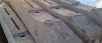
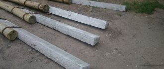
⇒Reinforced concrete pillars are made of different brands and are designated in this way, for example, concrete post SV 95-2, where 95 is the length of the post in decimeters, and 2 is the conditional load-bearing capacity.
According to GOST 23009-78, racks are manufactured in the following standard sizes:
- L – 9.5 meters (NE 95)
- L – 10.5 meters (CB 105)
- L – 11 meters (NE 110)
- L – 16.4 meters (NE 164)
They also differ in the method of reinforcement, on which the load-bearing capacity depends.
Power transmission line support racks SV 95
Reinforced concrete poles SV 95 are widely used for laying and installing networks with a voltage of 0.4 kV and for laying communication lines. They are mainly used for connecting summer residents to electrical networks when installing an additional power pole. For their manufacture, heavy concrete (class B30) is used, which complies with GOST 26633-91 standards. As a filler for this concrete, manufacturers use granite crushed stone with a strength index of at least M 1200 - M 1400, frost resistance F 300.
SV 95 racks can be operated at temperatures reaching -55 degrees Celsius. They are successfully operated in areas of category IV and can be installed where seismicity does not exceed 7 points on the Richter scale. Reinforced concrete power transmission line supports SV 95.2 and SV 95.3 are equipped with embedded products necessary to fasten structures and connect the necessary grounding elements. These racks taper towards the top and their length is 9.5 meters. The cross-section of the supports is rectangular and equal to: height at the base – 240 mm, at the top – 165 mm, width at the base and top is the same – 150 mm. The weight of the rack is 750 kg.
The SV-95 reinforced concrete pole at the manufacturing enterprise is supplied with embedded iron products intended for connecting structures and grounding parts.
Racks SV 110
Reinforced concrete racks SV 110 are designed for power lines with voltages up to 10 kV.
They can also be installed for communication lines. Reinforced concrete poles SV 110 are resistant to aggressive environments, low and high temperatures and can be successfully installed in areas with a high degree of fire danger. Reinforced concrete poles SV 110 also find their use as lighting supports. Their production is carried out using heavy concrete using the vibrocompression method. These concrete mixtures have a compressive strength class of B30.
The length of the SV 110-3.5 and SV 110-5 stands is 11 meters. At the base of the support the height is 280 mm, and at the top the height is 165 mm. The width of the base is 170 mm, the top is 175 mm. The weight of the concrete support is 1150 kg. The SV 110-3.5 posts have a design bending moment of 35 kNm, and the SV 110-5 posts have a design bending moment of 50 kNm.
Reinforced concrete supports SV 110 are made of heavy concrete with the following characteristics:
- Strength grade – M 400
- Frost resistance – F 200
- Waterproof – W 6
Each of them is equipped with embedded metal products designed to secure structures and connect parts of the grounding structure and are manufactured in strict accordance with GOST and TU standards.
All supports must have a certificate of conformity and a quality passport.
Support manufacturing technology
The main stage of production of support logs still involves mechanical processing in order to form technological openings with holes. Horizontal ends are protected using special pastes already at the basic finishing stage. If necessary, existing nicks, chips and webbing are corrected - they can be eliminated provided that the depth is no more than 10% of the diameter of the workpiece. To maintain accuracy during the machining process, the production of wooden power line poles at some enterprises involves the use of special templates. For example, the parameters of cuts and notches are checked using them.
Next begins the drying stage, which prepares the wood for impregnation. According to regulations, protective agents can only be applied if the humidity of the array is no more than 28%. Barked logs are dried in special thermal chambers, which have an unusual design. The fact is that in such units, hot air flows are not directed towards the workpiece, but circulate around it. Thus, cracking and overheating of the material is prevented.
Manufacturers of supports
In Russia, products in the form of components and consumables for equipping power lines are quite widely represented. One of the largest representatives of this niche is the Kotelnich Mast Impregnation Plant. This company has been manufacturing high-quality wooden poles for more than 30 years, and in recent years has successfully switched to high-tech automated production of products. However, many manufacturers of wooden power transmission line poles in Russia are engaged in updating their capacities, among which the companies “OSMK” and “ProfTrade” also stand out. If the first-mentioned manufacturer focuses specifically on the production of supports, then in the assortment of these companies you can also find reinforcing components, insulating materials and auxiliary elements specifically tailored to the characteristics of specific supports.
