Currently, trays made of reinforced concrete for heating mains have replaced the previously used brickwork. Trays are cheaper than bricks and the time required to build a channel for a heating main is several times less than to lay a brick box.
Reinforced concrete trays perform certain functions:
- channel for laying various pipelines;
- protection of pipes from rodents and any other types of damage;
- heat saving and no interaction of pipes with air;
- protection from ground and flood waters (it is possible to use trays even in seismically unstable areas);
- protection from harmful chemicals in places where they are present and accumulated.
As a rule, they are covered with lids. This gives advantages to track owners in case of unforeseen situations. The simplicity of the design allows you to quickly open exactly the area where the rupture occurred.
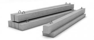
Photo: reinforced concrete tray for heating mains
There are several types of channels based on the installation method:
- channels with floors resting on them (CL);
- channels formed from covers with trays resting on them (CLp);
- channels from trays that rest on each other and connected using channels (CLs). Such channels are made with the condition that a person whose height is no more than 180 cm can move calmly inside. Only a few companies are engaged in the production of trays for such structures in the Russian Federation.
Before laying in the ditch, a sand cushion is made, which is necessary for direct and strong contact of the tray with the surface of the earth.
The seams between the trays and lids, as well as the holes intended for transporting and laying the product, are protected with rubber seals and filled with concrete. This is necessary to create a monolithic system.
Well elements
- GOST 8020-90
Concrete and reinforced concrete structures for sewer, water and gas pipeline wells - Series 3.900.1-14
Issue-1 Reinforced concrete products for round wells for water supply and sewerage - TMP 902-09-46.88
Album-2 Chambers and wells for rainwater drainage - TPR 901-09-11.84
Album-1 Water wells (explanatory note) - TPR 901-09-11.84
Album 2 Water wells - TPR 901-09-11.84
Album-3 Water wells
- GOST 3634-89
Cast iron hatches for inspection wells - GOST 3634-99
Manholes for inspection wells and rainwater inlets for storm drainage wells (technical conditions)
Dimensions according to GOST and prices of slabs for covering trays ↑
Like any other box, the design of the trays necessarily requires laying on top of the floor gutter. This must be done so that when filling with earth, it does not fall directly on the pipes.
Otherwise, the whole point of placing the pipeline system in trays is lost. Floors for trays are rectangular slabs of concrete or reinforced concrete, which must correspond to the dimensions of the concrete trays themselves.
Important! In addition to the overall dimensions, floor slabs must be made of concrete of the same grade as the trays.
This will preserve the integrity of the material structure of the entire box, consisting of a tray and a ceiling, which will be able to last for decades.
The building materials market offers the following slab sizes:
- slab length – found 740-2990 mm or more;
- slab width – found 400-2460 mm;
- height (or thickness) – found 50-160 mm;
- the weight of one unit of the slab is 100-2940 kg.
However, before any design of construction work, preliminary calculations must be made. But such calculations always require information about the sizes of slabs for trays and their prices.
To understand approximately what prices exist for certain slabs for tray floors, you can familiarize yourself with selective information about their parameters and costs:
Photo: information on the sizes of slabs for trays and their prices
Thus, the larger the size and thicker the slab, the more expensive it will be. After all, much more raw materials are spent on its production, which means that the price, accordingly, will be higher than for a plate that is thinner and smaller in size.
Thanks to preliminary information about the cost of floor slabs, it will be much easier to plan construction and make calculations for laying heating mains in trays.
Reinforced concrete trays
- Series 3.006.1-8
Issue 3-1 Prefabricated reinforced concrete channels and tunnels from tray elements. Trails. Plates, support cushions. Working drawings - Series 3.006.1-8
Issue 4-1 Prefabricated reinforced concrete channels and tunnels from tray elements. Trails. Plates, support cushions. Reinforcement and embedded products. Working drawings - Series 3.006.1-8
Issue 0-1 Prefabricated reinforced concrete channels and tunnels from tray elements. Trails. Design materials - Series 3.006.1-8
Issue 0-2 Prefabricated reinforced concrete channels and tunnels from tray elements. Route nodes. Design materials - Series 3.006.1-8
Issue 1-1 Prefabricated reinforced concrete channels and tunnels from tray elements. Trails. Trays. Working drawings - Series 3.006.1-8
Issue 1-2 Prefabricated reinforced concrete channels and tunnels from tray elements. Route nodes. Trays, boards, beams. Working drawings - Series 3.006.1-8
Issue 2-1 Prefabricated reinforced concrete channels and tunnels from tray elements. Trails. Trays. Reinforcement and embedded products. Working drawings - Series 3.006.1-8
Issue 2-2 Prefabricated reinforced concrete channels and tunnels from tray elements. Route nodes. Trays, boards, beams. Reinforcement and embedded products. Working drawings
Sale
has been producing a wide range of reinforced concrete products since 2009. We offer you to buy tray L 4-8 at a price cheaper than most companies in the Central Federal District. We guarantee the standard quality of our products and fulfill orders in a short time.
Our plant is located seven kilometers north of Tula. This feature determines the fact that most of our buyers are organizations from regions of the Central Federal District, such as Moscow, Bryansk, Kursk, Belgorod and others. However, we have quite a lot of experience in cooperation with companies from remote regions of Russia. Our managers will advise you on the conditions of joint work upon your first request.
Road slabs
- GOST 21924.0-84 (1988)
Reinforced concrete slabs for covering city roads (technical conditions) - GOST 21924.2-84 (1988)
Reinforced concrete slabs with non-prestressing reinforcement for urban road surfaces - GOST 21924.3-84 (1988)
Reinforced concrete slabs for urban road surfaces, reinforcement and assembly-butt products (design and dimensions) - GOST 25912.0-91
Prestressed reinforced concrete slabs PAG for airfield pavements
Specifications ↑
All possible characteristics of reinforced concrete trays, as well as the overall dimensions of the products, comply with various GOSTs. Let us consider the most necessary conditions for the production of reinforced concrete products.
GOST 13015.0-83 regulates the following conditions:
- frost resistance of products;
- waterproof trays;
- possible shapes and designs of trays;
- increased strength of the concrete used;
- quality of materials for the production of concrete itself;
- enhanced strength of the material in the presence of groundwater;
- dimensions and shape of the reinforcement embeds used;
- materials (steel grades) for the production of reinforcement products;
- possible deviations of the concrete layer protecting the reinforcement;
- protection of trays from corrosion.
The following requirements are defined for concrete used for the production of trays:
- all types of trays must be made of concrete no worse than M300;
- when compressed, concrete must have a strength of at least 70%;
- for the production of concrete, fillers with a particle size of no more than 15 mm can be used;
- the use of cement is possible at least 400;
- The addition of active additives is not acceptable.
Reinforcing products used in the production of reinforced concrete trays are strictly regulated by GOST 10922-90. The document indicates the type of steel from which they can be made (A-1, A-3) and the diameter of the wire (6 mm for longitudinal reinforcement and 5 mm for transverse reinforcement).
Photo: reinforcement products used in the production of reinforced concrete trays
The concrete surface of the trays should be fairly smooth, without large depressions. In some places, pits and cracks with a depth and width of no more than 3 mm are acceptable.
And in places where structures are fastened, damage to the surface layer is not allowed to exceed 1 mm. These aspects, as well as others, are regulated by regulatory documents.
If you comply with all the requirements necessary for the production of reinforced concrete trays, the products will be of the highest quality with a long service life.
Replacement of reinforced concrete channels is provided for by the operating rules and can be done no more than once every hundred years.
After this time, reinforced concrete structures begin to collapse, their tightness deteriorates and, as a result, pipelines and other systems installed in the channels are damaged.
Elements of pipe crossings
- TPR 503-7-015-90
Album 1 Round reinforced concrete culvert pipes made of long links with a hole of 1.0 1.2 1.4 1.6 for highways - TPR 503-7-015-90
Album 2 Round reinforced concrete culvert pipes made of long links with a hole of 1.0 1.2 1.4 1.6 for highways
- GOST 24547-81 (1991)
Links of reinforced concrete culverts for embankments of roads and railways (general technical conditions) - OST 35-27.1-85
Links of reinforced concrete round culverts for railways and roads
- Series 3.501.1-144
Issue 0-0 Prefabricated round reinforced concrete culvert pipes for railways and highways - Series 3.501.1-144
Issue 0-1 Prefabricated round reinforced concrete culvert pipes for railways and highways - Series 3.501.1-144
Issue 0-2 Prefabricated round reinforced concrete culvert pipes for railways and highways - Series 3.501.1-144
Issue 0-3 Prefabricated round reinforced concrete culvert pipes for railways and highways - Series 3.501.1-144
Issue 1 Working drawings, prefabricated round reinforced concrete culvert pipes for railways and highways - Series 3.501.1-144
Issue 0-4 Prefabricated round reinforced concrete culvert pipes for railways and highways - Series 3.501.1-156
Issue-0 Strengthening the channels of cones and embankment slopes of small and medium-sized bridges and culverts - Series 3.501.1-156
Issue-1 Strengthening the channels of cones and embankment slopes at small and medium-sized bridges and culverts
- Instruction VSN 32-81 for waterproofing structures of bridges and pipes on railways, highways and city roads
- SNiP 2.05.02-85 (1997)
Highways - SNiP 2.05.03-84 (as amended 1 1991)
Bridges and pipes
- Prefabricated round reinforced concrete culvert pipes for railways and highways
Installation
Based on SNiP 3.05.03.85, installation of non-passable channels occurs in accordance with SNiP 3-16-80, SNiP 3-15-76. The outer surfaces of channel elements supplied to the route must be covered with waterproofing in accordance with the working drawings. The installation of channel elements in the design position should be carried out in the technological sequence specified in the relevant regulatory documentation. During installation, constant geodetic support must be provided. The results of geodetic control after the final fastening of the structures of individual sections and tiers must be documented in an as-built diagram. When lifting and slinging, the following rules must be observed:
- when slinging with steel ropes, inventory pads should be installed under them to avoid damage to the concrete and rope;
- When lifting, lifting devices should be used to ensure uniform transfer of loads to the structures being lifted and slings;
- slinging should be done using inventory slings or special gripping devices with semi-automatic devices for remote slinging.
Lifting of structures should be done smoothly, without jerking, swinging or rotating the elements being lifted, usually using guy ropes. For guy ropes, hemp (according to GOST 483-75) or nylon (according to GOST 10293-77) ropes with a diameter of 19-24 mm should be used. Moving structures by pulling is prohibited. Installation of structures in the design position must be carried out according to accepted guidelines (marks, pins, stops, edges, etc.). Structures that have special mortgages or other fixing devices are installed using these devices. Unslinging of structures installed in place is permitted only after they are securely secured with permanent or temporary connections. Temporary fastening of installed structures should ensure their stability and unchangeable position until permanent fastening is performed. Before permanent fastening is carried out, structures must be checked for compliance with their design location and the readiness of mounting connections. An entry is made about the results of the check in the installation log. Before installing the upper trays (plates), the channels must be cleared of soil, debris and snow. Deviation of the slopes of the bottom of the heating network channel and drainage pipelines from the design value is allowed by 0.0005, while the actual slope must be no less than the minimum allowable according to SNiP II-G.10-73* (II-36-73).
Rectangular reinforced concrete pipes
- GOST 26067.0-83
Links of reinforced concrete free-flow pipes of rectangular cross-section for hydraulic structures - GOST 26067.1-83
Links of reinforced concrete free-flow pipes of rectangular cross-section for hydraulic structures (design and dimensions) - OST 35-27.2-85
Links of reinforced concrete rectangular pipes for railways and highways - Series 3.501.1-177.93
Issue 0-2 Prefabricated reinforced concrete rectangular culvert pipes for railways and highways - Series 3.501.1-177.93
Issue 1-1 Prefabricated reinforced concrete rectangular culvert pipes for roads and railways
Types of trays for heating mains, markings
Each tray contains data - tray brand, date of manufacture, size, weight, strength.
The marking includes information about the method of laying the trays:
- CL - floors rest on the channels;
- KLP - channels are assembled from covers and supporting parts.
- KLS - trays rest on each other, connected to each other by channels.
Reinforced concrete for heating mains
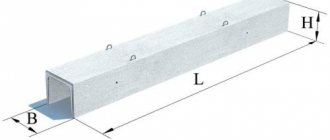
Standard trays have a rectangular or trapezoidal shape, the inner walls are located at an angle.
Dimensions are given in regulatory documents:
- length – 5970 mm, massive trays for ease of transportation and installation are produced with a length of 2970 mm;
- length of additional products – 720 mm;
- width – 420, 570, 780, 1160, 1480, 1840, 2160, 2460, 2780, 3380, 4000 mm (L1 – L38 series);
- wall height 360–1700 mm;
- thickness – 40–100 mm;
- internal channel width – 300–3600 mm;
- internal tray height – 300–1500 mm;
- bottom thickness – 60–200 mm.
The DorZhBI company in St. Petersburg offers to buy reinforced concrete trays for heating mains. We produce trays of all modifications, including those with additional elements. All products comply with GOST requirements and are made of high-quality concrete reinforced with steel reinforcement. We cooperate with large construction and industrial organizations and individuals. We will offer each client individual conditions, help you choose products, and deliver the order using our own vehicles. We carry out transportation by rail to remote regions of the Russian Federation. The quality of the product is confirmed by warranty cards. On the website you can familiarize yourself with the range of trays for heating mains, place an order, and find out the terms of payment.