| Trays and coverings of heating mains | Drainage trays | |
| Electrical trays | Drainage trays | |
| Road trays | Drainage trays | |
| Rain trays | Channel elements and channel floor slabs | |
| Channel chamber floor slabs | Heating main slabs with holes | |
| Beams of channel route nodes | Channel bottom slabs | |
| Support pads for heating mains | Backing boards | |
| Drain grates |
Our reinforced concrete plant produces all the necessary components for high-quality installation of pipelines for various purposes.
Concrete trays and coverings are designed to protect communications from external influences and to ensure high-quality drainage. Their use guarantees the durability and efficiency of any pipeline and communication system.
Reinforced concrete products for protective and engineering purposes
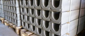
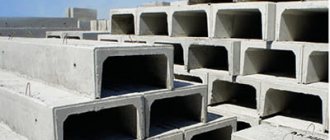
Reinforced concrete products , designed to extend the service life of the pipeline, are a U-shaped tray, which is installed with the open part up. When installing heating main trays, upon completion of the work, the open part of the structure is covered with a special reinforced concrete covering slab.
Such a box allows, if necessary, to replace a section of the pipeline or repair it without tearing the trench. Reinforced concrete products prevent the impact of soil movement on the pipeline. This base allows you to maintain its shape and is less susceptible to mechanical damage, the influence of precipitation and other unfavorable factors.
Design
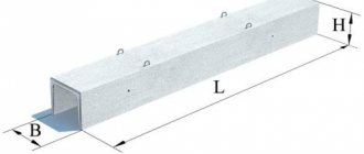
The design of non-pass channels must comply with series 3.903 class 14 issue 1-4, 3.903 class 14 issue 1-5. Figure No. 1 shows a view of a non-passable channel. Table No. 2 shows the linear dimensions of the channels and their mass.
Figure 1. Design of a no-pass channel.
As can be seen from Figure No. 1, the walls of the canals have a maximum thickness at the base and narrow as they move away from the main part of the canal. The thickness of the walls at the minimum wide points of the canal walls (maximum distance from the base), the thickness of the base and the thickness of the widest section of the canal walls are given in Table No. 3.
Concrete trays: types and purpose
All concrete trays have their own purpose, which determines the configuration of the product.
- Trays and slabs for covering heating mains. These products made from heavy grades of reinforced concrete perform a very important function - they act as thermal protection for pipes and protect them from the effects of ground movements.
- Drainage trays. Reinforced concrete products of this type, equipped with special drainage holes, are necessary for high-quality drainage of rainwater and melt water.
- Electrical trays. It is in them that cables for communication and electrical networks, security and fire alarms, video surveillance systems, etc. are laid.
- Gutters are an integral part of the drainage system. These structures are installed immediately during the construction of large construction projects for industrial and private purposes.
- Road drains allow for high-quality drainage of rain and melt water and moving soil from highways, city routes and sidewalks.
- Drainage trays are a necessary element of drainage and drainage systems installed near industrial facilities of residential buildings and cottages.
- Rain gutters provide high-quality drainage of rain and wastewater from the roadway, pedestrian and bicycle paths, parking lots and roadsides.
Dimensions
The dimensions of non-pass channels are given in table No. 2 and 3 and correspond to series 3.903 cl-14. The letter designations correspond to Figure No. 1.
| Product brand | Length L (mm) | Width B (mm) | Height H (mm) |
| KN-0 | 2330 | 490 | 300 |
| KN-0-M | 2990 | 490 | 300 |
| KN-1 | 1990 | 730 | 200 |
| KN-2 | 1990 | 970 | 250 |
| KN-3 | 1990 | 1210 | 320 |
| KN-4 | 1990 | 1440 | 400 |
| KN-5 | 1990 | 1530 | 450 |
| KN-6 | 1990 | 2030 | 530 |
| KN-7 | 1490 | 2800 | 620 |
Table 2. Linear dimensions of non-passing channels.
| Product brand | Thickness of the minimum wide section of the channel wall (mm) | Thickness of the widest section of the channel wall (mm) | Channel base thickness (mm) |
| KN-0 | 60 | 70 | 90 |
| KN-0-M | 60 | 70 | 90 |
| KN-1 | 60 | 80 | 80 |
| KN-2 | 60 | 90 | 100 |
| KN-3 | 60 | 90 | 100 |
| KN-4 | 60 | 90 | 100 |
| KN-5 | 60 | 90 | 100 |
| KN-6 | 60 | 110 | 100 |
| KN-7 | 100 | 120 | 140 |
Table 3. Thicknesses of non-passing channels.
Other reinforced concrete products for the installation of communication systems
The assortment of the ZhBI-4 plant includes not only trays and covering slabs , but also tray elements and floor slabs for various purposes and other components for the arrangement of communications and engineering systems.
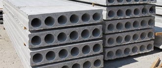
- Heating main slabs with holes from the ZhBI-4 plant are necessarily used for the construction of heating mains, as well as drainage structures.
- When installing collectors, you cannot do without reinforced concrete products such as beams for canal route nodes.
- Channel bottom slabs are used to create sealed and durable reinforced concrete boxes and trays in which communications are laid.
- Support cushions for heating mains are necessary elements of heat supply communications.
- Without backing slabs, it is not possible to create a reliable foundation for supports on which heavy loads are planned.
- Drain grates, just like trays, are an integral part of the drainage system.
All products presented on the ZhBI-4 website are manufactured in strict accordance with GOST. The catalog contains detailed images, describes the dimensions, main purpose, and the price list shows current prices.
Specialists from the ZhBI-4 plant will help you select all the necessary equipment for the construction of a drainage system, laying a heating main, a sewer collector and other engineering systems and structures, who are ready to answer any questions regarding the availability of the products the client is interested in, their cost and delivery conditions.
Heating main trays
| Trays for heating mains (heating networks) Series 3.006.1-2.87 | ||||
| Name | Dimensions (LxWxH, mm) | volume, m3 | Weight, t | Price for 1 unit. with VAT, rub. |
| L1-8 | 2970x420x360 | 0,17 | 0,44 | 3454 |
| L1d-8 | 720x420x360 | 0,04 | 0,11 | 1225 |
| L4-8 | 2970x780x530 | 0,36 | 0,9 | 5672 |
| L4d-8 | 720x780x530 | 0,09 | 0,23 | 1789 |
| L5-8 | 2970x780x680 | 0,44 | 1,1 | 7690 |
| L5d-8 | 720x780x680 | 0,11 | 0,28 | 2202 |
| L6-8 | 2970x1160x530 | 0,45 | 1,13 | 8059 |
| L6d-8 | 720x1160x530 | 0,11 | 0,28 | 2308 |
| L7-8 | 2970x1160x680 | 0,53 | 1,35 | 8163 |
| L7d-8 | 720x1160x680 | 0,14 | 0,35 | 2495 |
| L8-8 | 2970x1160x1000 | 0,78 | 1,95 | 10721 |
| L8d-8 | 720x1160x1000 | 0,2 | 0,5 | 2977 |
| L9-8 | 2970x1160x1310 | 1,02 | 2,55 | 15264 |
| L9d-8 | 720x1160x1310 | 0,26 | 0,65 | 4107 |
| L10-8 | 2970x1480x550 | 0,66 | 1,65 | 10948 |
| L10d-8 | 720x1480x550 | 0,17 | 0,43 | 2985 |
| L11-8 | 2970x1480x700 | 0,72 | 1,8 | 11984 |
| L11d-8 | 720x1480x700 | 0,18 | 0,45 | 3211 |
| L12-8 | 2970x1480x1010 | 0,96 | 2,4 | 15870 |
| L12d-8 | 720x1480x1010 | 0,24 | 0,6 | 3896 |
| L13-8 | 2970x1480x1320 | 1,26 | 3,15 | 18634 |
| L13d-8 | 720x1480x1320 | 0,32 | 0,8 | 6212 |
| L14-8 | 2970x1840x570 | 0,93 | 2,33 | 15507 |
| L14d-8 | 720x1840x570 | 0,23 | 0,58 | 4053 |
| L15-8 | 2970x1840x720 | 0,99 | 2,48 | 17559 |
| L15d-8 | 720x1840x720 | 0,25 | 0,63 | 5108 |
| L16-8 | 2970x1840x1030 | 1,26 | 3,15 | 20289 |
| L16d-8 | 720x1840x1030 | 0,32 | 0,8 | 5707 |
| L17-8 | 2970x1840x1330 | 1,5 | 3,75 | 25903 |
| L17d-8 | 720x1840x1330 | 0,38 | 0,95 | 6833 |
| L18-8 | 2970x1840x1640 | 1,86 | 4,65 | 29505 |
| L18d-8 | 720x1840x1640 | 0,47 | 1,18 | 8195 |
| L19-8 | 2970x2160x740 | 1,26 | 3,15 | 20864 |
| L19d-8 | 720x2160x740 | 0,32 | 0,8 | 6287 |
| L20-5 | 2970x2160x1040 | 1,5 | 3,75 | 21896 |
| L20d-5 | 720x2160x1040 | 0,38 | 0,95 | 6154 |
| L21-8 | 2970x2160x1340 | 1,77 | 4,42 | 26930 |
| L21d-8 | 720x2160x1340 | 0,44 | 1,1 | 9118 |
| L22-8 | 2970x2160x1640 | 2,07 | 5,18 | 31204 |
| L22d-8 | 720x2160x1640 | 0,52 | 1,3 | 8879 |
| L23-8 | 2970x2460x740 | 1,42 | 3,55 | 25235 |
| L23d-8 | 720x2460x740 | 0,36 | 0,9 | 7314 |
| L24-8 | 2970x2460x1040 | 1,62 | 4,05 | 28534 |
| L24d-8 | 720x2460x1040 | 0,41 | 1,03 | 7810 |
| L25-8 | 2970x2460x1340 | 1,89 | 4,73 | 32146 |
| L25d-8 | 720x2460x1340 | 0,47 | 1,18 | 9617 |
| L26-8 | 2970x2460x1640 | 2,19 | 5,48 | 35877 |
| L26d-8 | 720x2460x1640 | 0,55 | 1,38 | 9868 |
Reinforced concrete prefabricated trays for heating mains are manufactured according to Series 3.006.1-2 and belong to the tray elements of channels and tunnels.
The concrete used for the production of these products can be graded from M200 to M450. Heating main trays are marked with the letter L and two numbers - the serial number and the value of the vertical design load. The marking may contain the letter d, which means that this tray is an additional one. For example, for tray L4-8, tray L4d-8 will serve as an addition. All extensions are 740mm long. According to the above Series, the length of solid heating system trays should be 5970 mm, but for ease of transportation and installation, our plant, like many other manufacturers, makes trays 2970 mm long. This is allowed by the standard, since it preserves the serial reinforcement scheme for heating system trays. With this design, it is possible to use fractional markings in the name of the trays, for example L6-8/2, which will mean half of the nominal length of the serial product. By prior agreement with the customer, it is possible to manufacture a heating main tray with embedded products. They are often required for fastening communication elements inside heating system trays. Heating main trays are used for laying not only various pipelines, but also electrical cables. These products are used both in normal soil conditions and on subsidence soils. The heating main from these trays can be installed even under roads and railways. Semi-underground installation is possible. Typically, heating main trays are used together with covering slabs.
In the absence of groundwater for heating main trays, sand preparation with a thickness of no more than one hundred millimeters is made. In those places where the trays are adjacent to the chambers, special expansion joints are made and subsequently filled with bitumen. When laying steam pipelines every hundred meters, the heating main must have an installation outlet. For water networks this distance will be two hundred meters, and for electric networks - one hundred and fifty. To protect against corrosion, it is planned to cover the heating main trays with a layer of bitumen. Hermetically sealed tray insulation is also important because it prevents the leakage of air, which is contained in the heating main channel and has thermal insulating properties. This reduces possible heat loss.
Before starting the construction of a heating main from tray elements, it is necessary to carry out certain preparatory work. Firstly, it is necessary to clear the strip along the future heating main. Secondly, when carrying out excavation work, it will be necessary to guarantee the safety of existing communications running underground in a given place, or to relocate them. Also, do not forget about drains so that water does not stagnate in the trenches. The time interval between digging a trench and laying heating main trays in it should not be long. As a rule, these types of work go parallel to each other. The soil removed from the trench is accumulated in the form of a dump on both sides of the future heating main. If digging occurs during digging, the bottom is backfilled and then leveled with sand. The bottom of the trench is carefully compacted. This must be done in order to avoid future distortions of the installed trays. In winter construction conditions, installing a heating main tray on frozen ground is prohibited. Before installing the tray, it is necessary to warm up this area.
During the installation of heating mains from concrete trays, the joints between them are carefully sealed. In parallel with the joining of the trays, the heating main is filled with pipelines for various purposes. After the communications are installed inside the trays, they begin to backfill the trench using a bulldozer. Each layer must be compacted. In winter, the soil used for backfilling must be thawed.
Materials
When producing CN, heavy concrete with a density of at least 2100 kg/m3 according to GOST 26633-2012 must be used. The density of concrete should be determined according to GOST 12730.1-78. Concrete must be class B15 or B20 with water resistance W4 and frost resistance F150. Water for concrete must comply with GOST 23732-79. In the production of channels, hot-rolled reinforcement of a periodic profile of class A3 is used in accordance with GOST 5781-82 and cold-drawn reinforcing wire made of low-carbon steel in accordance with GOST 6727-80.
Transportation
Transportation of non-passable channels must comply with paragraph 8 of GOST 13015-2003 and paragraph 5 of series 3.903 class 14 issues 1-4, 1-5. During transportation, measures must be taken to prevent damage to the products. During loading and unloading operations it is prohibited:
- unload products with free fall;
- move products by dragging, without rollers and spacers.
Lifting, loading and unloading must be done using lifting machines using traverses and slings. The order of laying non-passable channels on the transported platform must ensure uniform distribution of the load relative to the axis of symmetry and the axes of the vehicle wheels. Transportation of products must be carried out taking into account the possibility of their installation directly from the vehicle. The gaps between the product and the sides of the vehicle should not be less than 150 mm.
| Non-pass channel (KN) (series 3.903 class 14 issue 1-4) | |
| Non-passage channel size | Number of channels in a scow 12 m long, p, (pcs.) |
| KN-1 | 38 |
| KN-2 | 28 |
| KN-3 | 22 |
| KN-4 | 18 |
| KN-5 | 12 |
| KN-6 | 10 |
| KN-7 | 6 |
