Changing the wall thickness Changing the wall thickness up to 10 cm is done using wooden overlays, a strip of plywood between the elements and TAR or SRZ crossbars fig. In Fig. The most stable option is option b, where the crossbar is held by two strands. Option c with a small crossbar arm is only allowed if there is also an element on a thinner wall or if stability is obtained due to two strands in the element.
Options d and e show possible anchoring when connecting small elements using TAR crossbars. Option e is unacceptable, since, firstly, the reinforcement often interferes with the passage of the strand and, secondly, a protective layer of concrete is not provided.
It should be taken into account that on one side there is no fastening of the joint with locks. If there is an end end nearby, forces have to be dissipated along the formwork.
What factors influence the strength of formwork?
It should be taken into account that too many factors influence the design of the panel fence. For example:
- Calculation of the strength of the material for the construction of the structure. Everyone knows that there are no absolutely identical boards. And their quality depends on the presence of knots, the degree of drying, etc.
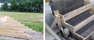
Wooden formwork panel
Correct calculation of the grade and properties of concrete. Concrete can have different consistencies. This directly depends on the ratio of the components that are included in it. You should also take into account the speed of pouring the mixture, the method of compacting it and reinforcing it.- From climatic conditions. In cold and hot weather, boards have different strength indicators. If the boards are dry, they can withstand more pressure than wet ones.
It is also necessary to pay attention to such a concept as formwork deflection. It is different for certain parts of the structure. For example, for the upper part, which is located above ground level, the deflection is no more than 1/400 of the length of the structure. For the lower part - 1/250 of this length. Of course, such results are very difficult to achieve. Therefore, it is better to play it safe and use stronger material.
It is best to make formwork with a certain margin of safety and in no case rely on what may be able to withstand.
A monolithic strip foundation is a very responsible design. Therefore, the calculation of the formwork load is based on certain requirements:
- Reliability and ability to withstand dynamic loads.
- Easy to assemble and disassemble wooden structure.
- No bending of the structure.
- Safety during work.
This is interesting: What is included in the working equipment of a motor grader
Concrete pressure and decision making
If during construction work it is customary to use metal formwork systems, then the deflection of the panels does not play a significant role. The walls of the structure cope well with deflection. But if the formwork is assembled from wooden elements, the deflection coefficient of the building material should also be taken into account. In the latter case, the calculation of wooden formwork is carried out with a safety margin. We recommend that you take into account the method of pouring the concrete mixture, the technical and weather conditions of the pour, and the setting speed of the solution.
But if you are interested in building a reliable and safe structure, it is wiser to turn to professionals. Our company will carry out all the necessary calculations, taking into account the region, seasonal factors, work conditions, etc. We are guided by the standards and construction regulations developed by GOST, which guarantees an impeccable result.
Types of formwork systems
In 8 out of 10 cases, removable formwork is used. It is organized from wooden boards, usually coniferous wood. This is an inexpensive and easily installed type of structure that can withstand significant loads, but is not durable and has one drawback - the hygroscopicity of the material. Plastic formwork does not have this disadvantage. It is light, but even less durable than wood. Its main advantage is smoothness. Minimal problems when removing the system.
The best and most reliable, but also expensive, are considered:
- steel formwork systems are a universal option. It is not suitable for private construction, since its increased weight requires additional investments in the rental of special equipment;
- aluminum formwork is a durable, but most importantly lightweight system. Its disadvantage is its susceptibility to corrosive processes, so contact with a liquid solution will be destructive.
Concrete pressure and decision making
If during construction work it is customary to use metal formwork systems, then the deflection of the panels does not play a significant role. The walls of the structure cope well with deflection. But if the formwork is assembled from wooden elements, the deflection coefficient of the building material should also be taken into account. In the latter case, the calculation of wooden formwork is carried out with a safety margin. We recommend that you take into account the method of pouring the concrete mixture, the technical and weather conditions of the pour, and the setting speed of the solution.
But if you are interested in building a reliable and safe structure, it is wiser to turn to professionals. Our company will carry out all the necessary calculations, taking into account the region, seasonal factors, work conditions, etc. We are guided by the standards and construction regulations developed by GOST, which guarantees an impeccable result.
General information
Every person when building a house is faced with the problem of floors.
Scheme of a prefabricated monolithic floor.
There are 3 options for solving the problem - wood (round timber and timber), slabs (hollow-core and reinforced concrete) and a monolithic floor (a full-fledged monolith and on iron beams). The last option is considered the most reliable, although its production will require spending the most effort, time and money. The first difficulty is the calculation of the monolithic floor. To do this, you will need to know exactly the entire construction process in order to be confident in each element used. And he goes in strict sequence.
Reduced adhesion of concrete to formwork
Problems may arise when dismantling the panel structure due to the adhesion of concrete to the material used. Several factors influence the adhesion force: shrinkage of the mixture, unevenness and porosity of the material. Concrete adheres more to wood and metal, less to plastic. In order to reduce coupling, it is necessary to take into account some factors to correctly calculate this value:
- The surface of the structure is formed from smooth materials.
- After installing the formwork and before pouring concrete, a special lubricant is applied to the inner surface of the structure.
The use of lubricants sharply reduces the adhesion of the mixture to the formwork. For example, when treating steel formwork with lubricant, the adhesion to concrete after 24 hours decreases by 4–5 times.
Permissible formwork deviations
During installation, it is necessary to check the level deviation of the formwork
As with any other technology, certain deviations are allowed in the installation of formwork, which are determined by SNiP Sh-15-76.
- During installation of the structure: deviation from the axis - 0.15 cm, from the axis of individual panel structures - 1.1 span lengths.
- Deviations from the vertical: a deviation of 0.5 cm is allowed along the height of one meter, and up to 2 cm throughout the entire height.
- The unevenness of the formwork for a length of up to two meters is 0.3 cm.
- Deviations of collapsible panels in length and width: up to one meter - 0.3 cm, more than one meter - 0.4 cm. Diagonally - 0.5 cm.
- The deviation of the edge of the shield is 0.4 cm.
Hidden deviations include the level of the trench base and the quality of its preparation.
SP 371.1325800.2017 formwork. design rules / 371 1325800 2017
| MINISTRY OF CONSTRUCTION AND HOUSING AND COMMUNAL SERVICES RUSSIAN FEDERATION | |
| SET OF RULES | SP 371.1325800.2017 |
FORMWORK
Design Rules
Moscow Standardinform
2018
Preface
Rulebook Details
1 CONTRACTORS - Joint Stock Company "Scientific Research Center (JSC "Scientific Research Center "Construction"), Limited Liability Company "Scientific and Technical" (LLC "STC "Stroyopalubka")
2 INTRODUCED by the Technical Committee for Standardization TC 465 “Construction”
3 PREPARED for approval by the Department of Urban Planning and Architecture of the Ministry of Construction and Housing and Communal Services of the Russian Federation (Ministry of Russia)
4 APPROVED by Order of the Ministry of Construction and Housing and Communal Services of the Russian Federation dated December 11, 2017 No. 1640/pr and put into effect on June 12, 2022.
5 REGISTERED by the Federal Agency for Technical Regulation and Metrology (Rosstandart)
6 INTRODUCED FOR THE FIRST TIME
In the event of a revision (replacement) or cancellation of this set of rules, the corresponding notification will be published in the prescribed manner. The relevant information, notification and texts are also posted in the public information system - on the official website of the developer (Ministry of Construction of Russia) on the Internet
CONTENT
Introduction
This set of rules has been compiled in order to improve the rules for designing formwork, improving its quality, improving the technology of formwork work and the construction of monolithic structures of buildings and structures.
The arch was made by the team of authors of LLC "NTC "Stroyopalubka" (candidate of technical sciences N.I. Evdokimov
,
E.A. Evdokimova
).
SET OF RULES
| FORMWORK Design Rules Formwork. Design rules |
Date of introduction - 2018-06-12
1 area of use
1.1 This set of rules should be applied when designing removable formwork of all types for the construction of buildings and structures.
1.2 This set of rules does not apply to the design of pneumatic and tunnel formwork.
Calculation of loads on vertical formwork according to DIN 18218:2010
Using the online calculator developed by MODOSTR specialists, you can calculate the loads on vertical formwork when concreting walls, columns or foundations . This online application implements the method for calculating the lateral pressure of a concrete mixture, set out in the German standard DIN 18218:2010. The technique makes it possible to take into account such parameters as the consistency of the concrete mixture, setting speed, speed of laying in formwork, density, temperature conditions, height of continuous concreting.
hydrostatic pressure of concrete
Assumptions:
- the formwork is installed strictly vertically with a deviation of no more than 5°
- concrete mixture of classes F1 - F6 is compacted with submersible vibrators, self-compacting concrete SCC is not vibrated
- concrete mixture is fed into the formwork from above
- the immersion depth of the vibrator does not exceed the height of hydrostatic pressure and is no more than 1 m
Questions, comments or suggestions for calculations can be sent to: This email address is being protected from spambots. You must have JavaScript enabled to view it.
When calculating formwork, the primary task is to determine the load that will be exerted on its complex. The calculation data is obtained taking into account many factors, including: the weight of the formwork components, the weight of the concrete mixture, the weight of the reinforcing elements, as well as the total weight of the scaffolding and workers involved in pouring. In addition, to ensure the stability of the structure and calculate the required number of supporting elements, it is necessary to calculate the wind load indicator. In general, the load experienced by the formwork is divided into vertical and horizontal.
Calculation of the maximum lateral pressure of concrete on the formwork walls
| Sealing method | Calculation formulas for determining the maximum lateral pressure of a concrete mixture, kPa | Limits of application of the formula |
| Using vibrators: | P = γH P = γ(0.27 + 0.78)К1К2 | |
| internal | Н ≤ R ν 4.5 provided that Н > 2 m |
- P
—maximum lateral pressure of the concrete mixture, kPa; - γ
—volumetric mass of the concrete mixture, kg/m³; - H
is the height of the laid layer of concrete mixture exerting pressure on the formwork, m; - ν
— speed of concreting the structure, m/h; - R, R
1 - respectively, the radii of action of the internal and external vibrator, m; - K
1 - coefficient taking into account the influence of the consistency of the concrete mixture: for a rigid and low-moving mixture with a cone draft of 0-2 cm - 0.8; for mixtures with a cone draft of 4-6 cm - 1; for mixtures with a cone draft of 8-12 cm - 1.2. - K
2 - coefficient for concrete mixtures with temperature: 5-7 ° C - 1.15; 12-17°C - 1; 28-32°C - 0.85.
This is interesting: How to calculate the volume of crushed stone for backfilling
Formwork for strip foundations, strength elements
Do you want to know how to properly make formwork for a foundation? Then seriously think about what and how many power elements will be needed (jibs, spacers, ties). Their size and quantity depend on what the foundation will be under your “birth nest”. After all, it’s one thing to pour a strip of shallow foundation, and another thing to fill the foundation wall of a basement floor 2.5 m high.
Without a well-thought-out power system, the formwork will simply break! Therefore, it is better to “be on the safe side” than to manually, urgently strengthen the frame, collect and throw the concrete back. Oh, this is not an easy job...
Therefore, experienced builders do not recommend using everything as power elements. “I blinded you from what was…” will not work in this case! “Make” these formwork panels even from used pallets, but for the strength elements, do not use rotten wood or questionable studs, and do not skimp on the cross-section of lumber.
The minimum size of beams suitable for racks, ties, crossbars is 50 x 60mm. Ideally – 50 x 100 mm. For plank boards, they take a board of twenty-five, thirty, and those who live very well can even order a 40-piece.
Vertical crossbars are installed in increments of 70 cm to 1 m. And with a recessed base, from 20 to 40 cm. Moreover, when building a foundation for the basement floor, all the jibs resting on one vertical board, tightening the wooden strip of the frame, with the other end must go to one point . Such installation of the jibs will give even high formwork sufficient rigidity.
Small panel formwork got its name because the area of the plywood sheet is from 1 to 3 square meters. m., and weight – up to 50 kg. The maximum calculated lateral pressure of concrete is up to 0.6 kPa. Such panel formwork can be assembled either manually or using special equipment, if you plan to make large panels from small panels, giving the formwork a larger overall size.
Alexander Balovsky from Arkhangelsk asks:
How to correctly calculate the pressure of concrete on formwork? What parameters influence this calculation, what should be taken into account?
Our specialist's answer:
When calculating the formwork, it is important to determine all the parameters that affect its strength and stability. Calculated data is obtained taking into account all influencing factors, including weight:
- additional equipment;
- concrete mixture;
- fittings;
- scaffolding and stackers performing pouring work.
To ensure strength and reliability, the wind influence on the structure is also calculated.
Calculation example No. 2
Let's assume that the situation is the opposite: we have in stock "inches" - boards 25 mm thick. What should be the distance between the support-braces (I)?
We consider: h 2 =0.75×G×n×l 2 /T, I=√T×h 2 /(0.75×G×n)=√ 800000×0.025 2 /(0.75×1000×1 ,2)=0.75 m
Of course, if the soil allows, you can carry out a simple calculation of the brick for the foundation and subsequently give preference to the brick foundation option - it does not require any work with formwork. But when constructing a reinforced concrete monolithic foundation, the presented calculations will not be superfluous.
An example of a full-fledged monolith
- sheet A3;
- pencil with eraser;
- roulette;
- laminated plywood 20 mm and thicker;
- hammer with nails;
- wooden beams (100*100) and metal spacers (20 mm and thicker);
- roofing felt
Diagram of a prefabricated floor slab.
- Drawing up a workplace plan indicating all supporting structures. This is necessary so that later there are no difficulties with support.
- Production of formwork. The material for the formwork is selected specifically for strength and the possibility of easy dismantling. At this stage, you should measure in advance the outer perimeter of the site where the floor will be laid. All joints must be perfectly adjacent to one another to achieve maximum strength. Vertical layers are nailed not to the edge, but on top of the bottom. This is done so that the pressure of the solution does not squeeze out the panels along with the nails.
- In the second stage, a support beam system is installed. You can use either wooden beams or metal spacers. Wooden beams are installed 1 per m2, while metal spacers are installed half as often. After installation, you should check each of them separately. If they pass the test 100%, you can proceed to the next stage. If the test fails, then reinstallation is necessary, up to a complete replacement. After all, they may not withstand concrete pressure of 500 kg + falling energy. After checking the beams themselves, you should climb up and walk along the formwork from above. If you wish, you can jump: it will hold up, which means the supporting structure was well made.
- The floor (also known as the ceiling in the future) part is covered with roofing felt or any other waterproofing material. When laying, you should make a small margin on each side of 5-7 cm. After which you will need to press down with something heavy so that the material does not lose its shape.
Lateral Load Calculation
The calculation of this value depends on the compaction method. The formula looks like this: P = γH, P = γ(0.27 + 0.78)K1K2, if laying vibrators are used. If they are internal, the limits of use of the formula are:
Calculation and design of formwork
- H ≤ R;
- ν < 0.5;
- ν ≥ 0.5 if H ≥1 m.
If styling is done using external vibrators, the limits for using the formula are as follows:
- H ≤ 2R1
- ν < 4.5
- ν > 4.5 if H > 2 m.
Here P is the maximum pressure of the solution in kPa, γ is the volume-weight indicators of the concrete pour in kg/m
3
, Н – height of the material layer in meters, ν – material pouring speed, m/h, R, R1 – operating radii of the internal and external vibrator in meters. If the fill is inactive, rigid, with a cone settlement parameter from zero to two cm, K1 takes the value 0.8. If from 4 to 6 cm – K1=1. When the cone draft is from 8 to 12 cm, K1 = 1.2.
K2 depends on the temperature of the composition and takes a value of 1.15 at temperatures from 5 to 7
O
C, 1 at temperatures from 12 to 17, 0.85 at temperatures from 28 to 32 degrees Celsius.
Calculation of load on formwork
Technical data
| Column diameter: | 25 cm to 75 cm in 5 cm increments |
| Column cross-section: | Round |
| Maximum concrete pressure: | 150 kN/m² |
| Column height: | 0.30 m to 8.40 m |
| Element height: | 0.30 m | 1.20 m | 2.40 m | 3.00 m |
| Compatibility: | TRIO, MAXIMO, RUNFLEX |
Other Features Powder coating prevents concrete from sticking and makes cleaning easier.
Formwork calculator Order a free calculation of the cost of the kit
Request a free estimate of the cost of the kit
Horizontal load
This set of influencing factors includes:
- wind load, whose value is calculated according to SNiP 2.01.07-85;
- indicator of concrete pressure on the walls of the formwork, for the calculation of which the following formula is used:
dB = mV where,
- db – the required indicator of concrete pressure kPa;
- m is the volumetric mass of the concrete mixture, kg/m3;
- B is the height of the concrete layer, m.
Horizontal load on side formwork
| Method of supplying concrete mixture to formwork | Horizontal load on side formwork, kPa |
| Descent along chutes and trunks, as well as directly from concrete pipes | 4 |
| Unloading from buckets with a capacity, m³: from 0.2 to 0.8 sv. 0.8 | 4 6 |
Also considered horizontal are vibration loads that occur when compacting a concrete mixture with special vibrating tools.
Read also
Common mistake: increasing loads too quickly
Common mistake: increasing loads too quickly The most common mistake among beginners is increasing loads too quickly. Many trainees want to achieve positive results so badly that they often let their ambitions take over.
FULL PAYMENT
FULL RECORD Evil always returns, and from our sad reality, it seems, is not going to leave at all. It settled firmly and for a long time, took deep roots, growing with violence and revenge. The driver of the dark cherry Ikarus, Viktor Telnov, was going to
Calculation
Crew Crew (military), a group of soldiers directly servicing a gun, mortar, machine gun, as well as a radio station and some other combat equipment. The R. is headed by the commander of the gun (mortar, machine gun). The soldiers who make up the R. are called numbers, each R. number.
Match the method of fastening the rope in the upper working area and the distribution of loads on the fastening points:
42. Match the method of fastening the rope in the upper working area and the distribution of loads on the fastening points: a. 1. 100% and 100%; 2. 58% and 58%; 3. 50% and 50%b. 1. 50% and 50%; 2. 100% and 100%; 3. 58% and 58%c. 1. 50% and 50%; 2. 58% and 58%; 3. 100% and
2.2. Methods for calculating power consumption and electrical loads
2.2. Methods for calculating electricity consumption and electrical loads Determination of the future demand for electricity is carried out in order to compile electricity balances for the energy system and identify the need to introduce new energy sources. Definition
Appendix 7 CT load parameters
Appendix 7 CT load parameters Table A7 End of table. P7 The table uses the following designations: ZH, RK, Zp, RPEP - CT load resistance, active resistance of connecting (signal) cable cores, relay coil resistance and transition resistance in
Training load intensity scale
Training load intensity scale After heavy physical activity, the pulse returns to its original values after 20–30 minutes, sometimes after 40–50 minutes. If at the specified time the pulse does not return to its original value, it means that great fatigue has set in. AND
Budget calculation
Budget calculation Demidych took a sip of water from a small bottle that cost one American dollar and barked: “Taxi, guys.” The men, 160 cm tall, dressed in khaki pants and washed-out T-shirts, stood up busily and asked importantly: - Ten dollars,
Budget calculation
Calculating a budget In Thailand you can live and travel on a very budget; fortunately, prices for accommodation, food, excursions and transport are much lower than in Europe and are designed for a wide range of budgets. A budget of $500 per month (about 500B per day) means living in the most
Pouring the main slab
Monolithic floor installation diagram.
- automixer with sleeve;
- cement mortar (1 cement grade 400 and above, 3 sand, volume of water - as needed);
- shovel;
- bayonet shovel;
- polyethylene film;
- water;
- crowbar.
When pouring, it is important to consider that equipment and, if possible, several people will be involved in this process. An automixer is needed for the reason that it is better not to even try to mix the solution manually, because... The slab must be poured 1 day in advance. This will help avoid delamination, which can result in cracks or even simple collapse. A prerequisite for an automixer is the presence of a sleeve for supplying the solution to the floor.
While applying the mixture, one person constantly moves with a hose in his hands, and assistants plow each level of the solution with shovels. This is required in order to release the air accumulated in the cement. This will significantly add strength to the future floor. Plowing of the lowest layer should be done with extreme caution, because... this may lead to rupture of the waterproofing. It is also worth considering that when moving, reinforcement bars will get in the way under your feet, which should be carefully walked around. No matter how securely they are secured, they can be a tripping hazard.
Movement and regular redirection of the solution flow during pouring is required in order to avoid excessive stress on the support system, because Even the strongest example of a metal spacer will not withstand pressure for long. Plus, it will give assistants the opportunity to do their jobs.
After the filling has been completed, the entire slab should be covered with plastic film for 27-29 days, and the first half of the period will need to be slightly moistened with water so that the solution gains maximum strength.
After the allotted time, the supporting structure should be removed, the plastic film should be removed, and only then the entire formwork should be dismantled using a crowbar. There is no need to make any special efforts here, because... The specificity of the plywood coating does not allow it to stick to the mortar.
How to correctly calculate the bottom of metal formwork?
Independent execution of work on pouring the foundation for a future structure and its construction requires careful calculation and installation of formwork. This is a key point in the construction process, since the reliability, safety and durability of the structure depend on it. Formwork is an auxiliary building object necessary for concreting load-bearing structures, floors, internal partitions and other structural elements of a monolithic building.
Construction formwork consists of:
- load-bearing panels, which ensure the hardening of concrete in a certain form, experience its load;
- supporting elements;
- fasteners that fix the panels in a given position are subject to loads;
- other additional elements.
Each of the listed formwork components will experience certain loads during operation. In order for a structure to properly fix the shape of concrete and withstand its pressure, the elements must meet certain physical and technical characteristics and have the correct standard size. Therefore, you must first do:
- calculation of the bottom of metal formwork;
- calculating the strength and endurance of structural elements taking into account vertical/horizontal loads;
- calculation of permissible and possible deformations of the components of the formwork system - deflections during concreting should not exceed 1/200-1/400 of the span;
- calculation of structural stability - take into account the dead weight of the formwork, the weight of the reinforcement, the weight of the poured building mixture, the moment of concreting, etc.;
- calculate the parameters of the wind load - this will be necessary to determine the characteristics and number of retaining elements of the structure.
Accurate calculation of the concrete pressure on the formwork and other parameters from the list above will ensure the stability of the molding structure and maximum physical and technical characteristics of the monolithic elements of the building. If the construction project is complex or you have never made such calculations before, contact our company. We will help you make correct calculations in accordance with the requirements of SNiP and GOST. So how to do the calculations correctly?
Concrete mortar recipe
There are many recipes for concrete mortar poured into foundations. But there is a classic version, in which the ratio of cement, sand and crushed stone is: 1: 2: 4. This is where the problem lies. The thing is that sand and crushed stone are sold in cubic meters, and cement in kilograms. How to calculate the cubic capacity of the solution in this case, what to take as a basis: volume or weight. Of course, everything can be converted from one unit of measurement to another, taking into account the density of the materials used.
- One cubic meter of river sand contains 1.63 tons.
- Crushed stone 1.4 tons. Here a lot depends on the fraction of the material. The smaller the granules of the material, the denser it is, and therefore the greater the weight.
- The density of cement depends on its brand. Therefore, different brands have different volume-to-weight ratios. For example, grade M 400, by the way, is what is most often used for pouring the foundation; the ratio is 0.9-1.0 t/m³.
In order not to make all these transitions from one unit of measurement to another, builders calculate in buckets (10 l). Accordingly, the classic recipe for concrete mortar will consist of one bucket of cement, two buckets of sand and four crushed stone. There are standards for the weight of bulk material poured into a bucket. It holds either 19.6 kg of river sand, or 15 kg of crushed stone, or 10 kg of cement. Taking into account the addition of water, 24 - 25 kg of ready-made concrete is placed in one bucket.
Correctly calculating each ingredient of the concrete mixture makes it possible to correctly mix the solution, taking into account its brand:
- Concrete grade M 150 is used for pouring for small structures.
- M 200 for one- and two-story houses and cottages.
- M 300 for large heavy buildings.
For example, grade M 200 is calculated as follows: 1 kg of M 400 cement, 1.9 kg of river sand, 3.7 kg of medium fraction crushed stone (20-40 mm).
Of course, before you calculate how much concrete you need, you need to accurately determine the brand of mortar . Because you can play on the brand of cement by purchasing a low brand at a low price. After all, M 400 cement is cheaper than M 500. Therefore, the recipe with M 500 cement will be: 1: 3: 5. That is, by increasing the grade of cement, you can add less of it to the solution. True, this increases the volume of added fillers.
Foundation. Calculators for calculating the consumption of reinforcement, boards for concrete formwork
The importance of the foundation for any building is difficult to overestimate, because a reliable foundation of a building is the primary condition for its long-term trouble-free operation. You can build any, no matter how strong and beautiful walls, a well-designed and installed roofing system, reliable floors, and carry out expensive finishing. But all this can “go to waste” if errors were made when calculating the foundation, and during its construction, negligence was shown, unacceptable simplifications were made, low-quality materials were used, and the established technology was violated.
DIY foundation
So, the foundation is a key stage of any construction, which sometimes takes up to a third of the total budget. In an effort to save some money, some potential homeowners are seriously thinking about the problem: is it possible to build a foundation with their own hands? The answer to this question, unfortunately, is not obvious. It’s one thing to create the foundation for a small country house, garage or outbuilding, and quite another thing to create a full-fledged country mansion with several levels, and even with adjacent extensions.
Main types of foundations
There are quite a lot of varieties of foundations used in individual construction, but mainly four basic schemes are used, as well as their various combinations. And the main types include strip, columnar, slab and pile foundations.
Calculator for calculating the minimum number of main longitudinal reinforcement bars
Specify the requested values and click “Calculate the minimum number of rods”
- Estimated height of the tape (including depth and base), meters
- Estimated tape thickness, meters
- Reinforcing bar diameter
If you get 3 rods, then usually their number is increased to four to achieve the design as shown in the figure above. With another odd number, this unpaired rod can be used additionally in one of the tiers, mainly in the lower one.
The rods are connected into a common structure by tying with wire. Welding of a reinforcement frame can only be carried out under certain conditions, using special types of reinforcement, and only by highly qualified welders, so you cannot resort to this method in conditions of independent construction - you can ruin all the work done
Tied reinforcement belt
The reinforcement bars in one row are joined with a mandatory overlap of 50d, that is, for the most common diameters of 10 or 12 mm, this value ranges from 500 to 600 m. This must be taken into account when calculating the required amount of material.
Particular attention is paid to corners and abutment areas. No cross connections are allowed - there are special methods for linking these nodes. They are clearly shown in the illustrations below.
Basic rules for tying reinforcement belts at corners and junctions
In order for the reinforcing belt to fully perform its functions and, moreover, not to suffer from corrosion, the rods must be located at a distance of at least 50 mm from the outer walls of the concrete strip. This is achieved by installing supports from below, as well as special calibration inserts placed on the longitudinal rods - they rest against the walls of the formwork and hold the reinforcement at the required distance from them
Such an insert-liner will not allow the reinforcement bars to bend towards the walls of the formwork
Now let’s talk about how much reinforcement you will need. It would seem that everything is simple, the length of the foundation strip is known, and the number of rods in the cross-section is also known. But we must not forget about overlaps. Obviously, the more there are, the more significant the material consumption will become. The standard length of reinforcement 10÷16 mm is 11.7 meters. But it is not always possible to organize the delivery of such “long lengths” and you have to resort to cutting the rods in half - and this again increases the number of overlaps. So you will have to decide what is more profitable - order special transport or be satisfied with the increase in costs.
To make it easier to navigate, use the calculators below:
Reinforcement consumption calculators
Specify the requested values and click “Show reinforcement consumption options”
Length of the foundation strip (perimeter of the house and, if any, internal lintels), meters
Estimated number of longitudinal reinforcement bars
Now - a smooth reinforcing rod for clamps - vertical and horizontal jumpers. They are usually prepared from one piece of rod, bent into the shape of a rectangle with vertices at the location of the longitudinal main reinforcing bars, with an extension on one side by 100 mm to tie into a rectangular shape (shown in the illustration above).
As a rule, a diameter of 6 mm is sufficient for clamps (for a tape height of 800 mm or more - 8 mm). The installation step of the jumpers has already been mentioned - with the most economical arrangement, it should not exceed 0.75 of the height of the tape. In addition, it is necessary to take into account the compaction of the installation step at the corners and abutment areas.
The standard length of the rods is 6 meters, and it is quite possible that part of each will be scrapped.
All this is taken into account in the calculator below:
Calculator for calculating the number of smooth reinforcing bars for making clamps
Specify the requested values and click “Calculate the number of rods for clamps”
Length of foundation strip, meters
Total tape height, meters
Tape thickness, meters
Most often, metal depots sell products not by footage or number of rods, but by weight, in kilograms or tons. You can also convert to these units of measurement:
Calculator for converting the amount of reinforcement into tons
Enter the requested values and click “Convert to tons”
Calculated number of standard 6-meter rods
The quantity was calculated for:
Calculated number of rods
Formwork materials
To fill a monolithic belt, one cannot do without high-quality formwork that can withstand the pressure of liquid concrete at the filling stage and give the necessary geometry to the maturing foundation belt.
Variant of monolith on I-beams
Scheme of a monolithic floor with beams.
- beams (I-beams);
- laminated plywood 20 mm and thicker;
- hammer with nails;
- wooden beams (100*100) and metal spacers (20 mm and thicker);
- roofing felt;
- rod for fittings A500C;
- Bulgarian;
- soft wire;
- automixer with sleeve;
- cement mortar (1 cement grade 300 and above, 3 sand, volume of water - as needed);
- shovel;
- bayonet shovel;
- polyethylene film;
- water;
- crowbar.
This type of monolith has great similarities with a full-fledged one, but it has its own distinctive features. To begin with, you should definitely take into account that the example of this slab is more functional, but due to the smaller amount of concrete and reinforcement, it will not be as strong. An undoubted advantage, in turn, will be the ability to lay such a floor not only between the 1st and 2nd floors, but also on the basement, or when creating a multi-story building.
The first difference will be the start of work. The first step is not to lay out the formwork, but the beams. They are placed every 0.5 m, preferably on the narrowest side or so that when splicing, losses are minimal. It is most convenient to give an example of such a splice using the most popular 10*10 houses, where the joint runs exactly in the center and the projection beyond the load-bearing walls is minimal.
The second difference will be the height of the formwork, because here you will no longer need 0.3 m, but 0.15-0.2 m will be enough. This is due to the fact that there is no longer such an urgent need to increase the thickness in order for the structure to support itself. I-beams will do just fine as support, but such an overlap will no longer have high insulating properties.
Based on the second point, it follows that the amount of reinforcement will be reduced by half (from 2 levels to one), as well as the amount of concrete - by half or a third. But the hardening time will remain exactly the same, because... the rate of strength gain does not depend on the amount of concrete, but solely on time. In this case, especially cautious people use triple lathing made of reinforcement, which allows for additional strengthening of the structure, but this option is considered unprofitable in terms of price and quality.
The beams are then convenient to use for various purposes, but most often they are required for installing electrical wiring and creating suspended ceilings.
How to choose formwork material
Formwork for strip foundations are panels sold from wooden boards. For the manufacture of such a structure, boards made of wood of any species are suitable. For economy, and taking into account the fact that the use of the material is limited, boards of inexpensive species are used. You can use both cut and uncut boards. The shields should be knocked down so that the front part is inside the trench. Watch the video on how to make your own formwork.
Care should be taken to ensure that the surface inside the shield fence is as smooth as possible. When choosing wood for a shield fence, special attention should be paid to its length and thickness. The calculation of the length depends on the size of the foundation trench. The shields should protrude slightly beyond the boundaries of the foundation. Since concrete creates a fairly high pressure on the walls of a wooden structure, the boards are chosen of such a thickness that the boards are able to withstand this load. The optimal board width for installing a fencing structure is considered to be 25–50 mm.
You can use timber of greater thickness, but in no case should you use thin boards. The structure may not withstand, and correcting errors when pouring the foundation is a very labor-intensive and expensive pleasure.