- 1 Concept, features and system of information sources 1.1 Standard GOST 3455 - 59
- 1.2 Standard GOST 2.306 - 68
- 1.3 GOST R 21.1207-97
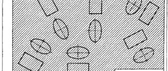
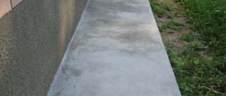
Most often, construction is not complete without concrete construction drawings. One of their elements is shading. Let's try to understand its design system.
Hatching of concrete GOST R 21.1207-97.
Hatching concrete according to GOST standards
How is reinforced concrete shading done correctly in drawings? Are there any standards establishing the method of types and design of sections of building structures? We have to find answers to these and some related questions.
Information sources
They will serve us as:
- GOST 3455-59.
- GOST 2.306 - 68, which replaced it.
Investigation
As it turned out much later, the drawing teacher simply did not know about the new standard adopted upon completion of his higher education and taught schoolchildren the same way he himself was taught.
GOST 3455 - 59
The standard began to function on January 1, 1959 and was canceled exactly 12 years later, on January 1, 1971. Its name is “Drawings in mechanical engineering. Hatching in sections and sections.”
We are obviously interested, first of all, in the material designation system adopted in the document.
GOST 2.306 - 68
When making a drawing with your own hands according to GOST, you must adhere to several rules:
- Oblique lines are drawn at an angle of 45 degrees.
But: this angle can be maintained not only relative to the drawing frame, but also relative to the axis or contour of the image.
So, in accordance with current regulatory documents, the instructions for shading concrete in the drawing are clear: it is indicated by dash-dotted lines. What happens if you use an outdated designation?
Fortunately, the cost of inaccuracy is not too huge: in accordance with the document we just studied, when constructing drawings it is allowed to use designations not provided for by it. It is only necessary to explain them in the drawing.
GOST R 21.1207-97
As is easy to notice, we did not find a valid GOST for shading reinforced concrete. In the old document the designation was there, in the new one it fell through the ground.
So what to do when constructing a drawing? Take advantage of the loophole with a footnote and arbitrary designation of the material below? Or do some rules still exist?
The answer can be found in a rather unexpected place - the standard regulating symbols in road construction, when constructing road drawings.
Along with asphalt, bulk soil and waterproofing materials, the document includes:
Conclusion
We hope that our material answered all the reader’s questions related to the designation of concrete in the drawings. As always, additional thematic data can be found by watching the video in this article. Good luck!
What is construction documentation?
Construction documentation consists of a set of design, estimate, executive and working materials compiled at different stages of preparatory work. It is impractical to list them completely; it is enough to understand - there are a lot of documents, all of them are used at different stages of preparatory or construction work. There are graphic and text materials showing the architectural, engineering and design features of the project. Text materials are used at the stage of preparation and processing of the project. Working drawings occupy an important place among other documents, since they are the basis for the process of project implementation - laying or assembling building structures.
To put a large number of documents in order, SPDS (System of Project Documentation for Construction) was created. It establishes uniform rules for the design and presentation of data on an existing project. SPDS standards ensure compliance with other documentation systems (for example, with the Unified System of Design Documentation, ESKD). This made it possible to combine disparate requirements and standards and eliminate many regulatory discrepancies and contradictions.
ESKD GOST 2. Rules for applying shading in drawings
Designations of graphic materials in sections
Designations of graphic materials in views
Rules for applying shading in drawings
The graphic designation of the material in sections and in views is shading performed with thin solid lines. The shape of the hatching in accordance with GOST 2.306-68 gives an idea of the material from which the part is made.
Designations of graphic materials in sections
Graphic designation of materials in sections, depending on the type of materials, must correspond to those given in table. 1.
Table 1. Graphic designation of materials in sections
Table 2. Graphic designation of materials on the view (facade)
| Material | Designation |
| 1. Metals | |
| 2. Corrugated steel | |
| 3. Expanded steel | |
| 4. Masonry of building and special bricks, clinker, ceramics, terracotta, artificial and natural stones of any shape, etc. | |
| 5. Glass |
Kawabanga!
Expanded clay concrete blocks: types, sizes, scope of application Table 3. Designation of mesh and backfill made of any material (in cross-section)
| Material | Designation |
| 1. Grid | |
| 2. Backfill |
Rules for applying shading in drawings
Oblique parallel hatch lines should be drawn at an angle of 45° to the image contour line (Fig. 1) or to its axis (Fig. 2) or to the drawing frame lines (Fig. 3)
| Figure 1. Hatching at an angle of 450 to the contour line | Figure 2. Hatching at an angle of 450 to the axis |
Figure 3. Hatching at an angle of 45
If the hatch lines drawn to the drawing frame line at an angle of 45° coincide with the contour lines or center lines, then instead of an angle of 45°, an angle of 30° or 60° should be taken (Fig. 4 and 5).
Hatch lines should be drawn slanted to the left or right, but, as a rule, in the same direction on all sections belonging to the same part, regardless of the number of sheets on which these sections are located.
| Figure 4. Hatching at an angle of 300 to the drawing frame | Figure 5. Hatching at an angle of 600 to the drawing frame |
Figure 6. Hatching of narrow and long areas
Figure 7. Hatching of narrow and long areas Hatching of all symbols in this case is done by hand.
Figure 8. Hatching of narrow and long areas
| Figure 9. Hatching of narrow areas whose width in the drawing is less than 2 mm. | Figure 10. Hatching of narrow areas whose width in the drawing is less than 2 mm. |
Figure 11. Sample shading of adjacent areas
Figure 12. Sample shading of adjacent areas
For large cross-sectional areas, as well as when indicating the soil profile, it is allowed to apply the designation only at the contour of the section with a narrow strip of uniform width (Fig. 13).
Figure 13. Sample of large area shading
Concept of aerated concrete
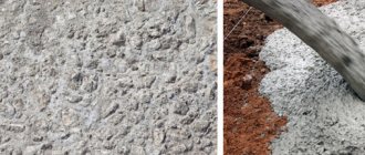
Aerated concrete is one of the types of cellular concrete. It is made from a mixture of sand, lime, cement, water and a gas-forming agent, most often aluminum powder.
As a result of the reaction of the latter with quicklime, the solution swells. The result is a material filled with cells. This structure gives aerated concrete special properties and qualities, which we will consider below.
First, let’s figure out what aerated concrete is.
Types of material and scope of application
Depending on the purpose, in accordance with GOST 25485-89, aerated concrete can be:
- Thermal insulation, density 300-400. It has a low thermal conductivity coefficient and is used exclusively as a material for insulation, since such products cannot withstand any loads other than their own weight due to their low density.
- Structural and thermal insulation. Its density varies from 500 to 900. It is more durable and is used for the construction of building walls and partitions. This type of aerated concrete is most common among private developers.
- Structural. The most durable type. Its density is 1000-1200. It is used for the construction of buildings up to 3 floors high.
However, the thermal conductivity coefficient increases significantly, so this material requires additional insulation.
Using the table, let us consider the relationship between the strength of products and their thermal conductivity.
Strength and thermal conductivity of aerated concrete:
| Type of aerated concrete | Strength grade | Coefficient of thermal conductivity |
| Thermal insulation | D300 | 0,09-0,11 |
| D400 | 0,11-0,12 | |
| Structural and thermal insulation | D500 | 0,12-0,13 |
| D600 | 0,14-0,15 | |
| D700 | 0,18-0,21 | |
| D800 | 0,21-0,23 | |
| D900 | 0,23-0,26 | |
| Structural | D1000 | 0,23-0,28 |
| D1100 | 0,28-0,34 | |
| D1200 | 0,29-0,38 |
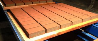
Since we are talking about the use of the material, it was worth mentioning how aerated concrete and concrete in general are indicated in construction projects on the drawings. Hatching of aerated concrete in the drawings is indicated in the form of dotted strokes - lines at an angle. This is clearly shown in the photo below.
Also, depending on the type of hardening, aerated concrete is divided into autoclave and non-autoclave. Autoclaved aerated concrete (synthetic hardening aerated concrete) is distinguished by the fact that the final stage of production is the processing of products in an autoclave under high temperature and pressure.
The process of releasing material occurs in a fairly short time. Non-autoclaved aerated concrete (hydration-hardening aerated concrete) hardens under natural conditions. Sometimes it is slightly heated in special machines to a low temperature in order to speed up the process. Such aerated concrete reaches brand strength within 28 days.
It is somewhat inferior in characteristics to its autoclave competitor. This concerns, first of all, strength, frost resistance, thermal conductivity and durability.
Comparison of synthetic and hydration-hardening aerated concrete:
| Indicator name | Value for autoclaved aerated concrete | Value for non-autoclaved aerated concrete |
| Thermal conductivity of dry products | From 0.09 to 0.38 | From 0.11 to 0.40 |
| Frost resistance, cycles | Up to 150 | Up to 50 |
| Shrinkage, mm/m2 | 0,3 | 0,5 |
| Strength grade | From B2.5 | From B 1.5 |
| Product color | white | Grey |
| Durability, years | Up to 200 | Up to 50 |
| Brand by density | 300-1200 | 300-1200 |
According to the type of silica component, aerated concrete blocks can be made using:
- Pesce;
- Zole;
- Other secondary industrial waste.
Depending on the type of binder, aerated concrete is:
- On a cement binder;
- On slag;
- On limestone;
- On ash;
- On mixed.
The products contain 15-50% of the main component.
In accordance with the accuracy category, aerated concrete products are divided into:
- Blocks of the first category of accuracy;
- Blocks of the second category of accuracy;
- Blocks of the third category of accuracy.
Hatching concrete according to GOST standards
How is reinforced concrete shading done correctly in drawings? Are there any standards establishing the way of designing sections and types of building structures? We have to find answers to these and some related questions.
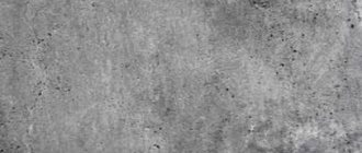
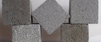
This is what concrete looks like in cross section. How is it indicated on the drawings?
Information sources
They will serve us as:
- GOST 3455-59.
- GOST 2.306 - 68, which replaced it.
Investigation
As it turned out much later, the drawing teacher simply did not know about the new standard adopted after he received higher education and taught schoolchildren the same way he himself was taught.
GOST 3455 - 59
The standard came into force on January 1, 1959 and was canceled exactly 12 years later, on January 1, 1971. Its title is “Drawings in mechanical engineering. Hatching in sections and sections.”
We are, of course, interested, first of all, in the material designation system adopted in the document.
Designations from the old standard.
GOST 2.306 - 68
This is how concrete began to be designated after the adoption of the new standard.
When making a drawing with your own hands according to GOST, you need to adhere to several rules:
- Oblique lines are drawn at an angle of 45 degrees.
However: this angle can be maintained not only relative to the drawing frame, but also relative to the axis or contour of the image.
On all sections of one part, the hatching step is the same.
So, according to the current regulatory documents, the instructions for shading concrete in the drawing are quite clear: it is indicated by dash-dotted lines. What happens if you use an outdated designation?
Fortunately, the cost of error is not too high: according to the document we just studied, when constructing drawings it is allowed to use symbols not provided for by it. You just need to explain them in the drawing.
GOST R 21.1207-97
As is easy to see, we did not find a valid GOST for shading reinforced concrete. The designation was present in the old document, but disappeared in the new one.
So what to do when constructing a drawing? Take advantage of the loophole with an arbitrary material designation and a footnote at the bottom? Or do some rules still exist?
The answer can be found in a rather unexpected place - the standard regulating symbols in road construction, when constructing road drawings.
Kawabanga! Autoclaved cellular concrete blocks
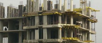
Reinforced concrete is actively used in road construction. The photo shows the Branicky bridge in Prague.
Along with asphalt, waterproofing materials and bulk soil, the document includes:
Designations according to GOST R 21.1207-97.
Conclusion
We hope that our material answered all the reader’s questions related to the designation of concrete in the drawings. As always, additional topical information can be found by watching the video in this article. Good luck!
Latest innovations
The GOST of 1973 had a significant drawback: it did not have a standard for describing reinforced concrete. This explains the need to develop GOST R 21.1207−97. This flaw was corrected in the installed template and the necessary designation was added.
Most often, this standard is used when road work is carried out. In addition to asphalt, as well as other building materials, in this template a special place is given to the following points:
- reinforced concrete, which is equipped with stressed reinforcement - 2 solid lines are used alternately, followed by one dotted line;
- reinforced concrete - solid and broken lines are drawn in turn;
- The shading of concrete in the diagram is indicated by a dotted line.
The main task when using reinforced concrete shading is the need to show, with the help of design drawings, the structure that needs to be implemented. Conventions help greatly in accomplishing this task.
Today, two main established templates are considered valid; both GOST standards are used in the construction industry and mechanical engineering. These templates enable builders to quickly determine the required building materials during the construction of various structures.
GOST 2.306-68* “ESKD. Designations of graphic materials and rules for their application on drawings"
UNIFIED SYSTEM OF DESIGN DOCUMENTATION
SYMBOLS, GRAPHICS AND RULES
THEIR APPLICATIONS ON THE DRAWINGS
IPC PUBLISHING HOUSE OF STANDARDS Moscow
Unified system of design documentation
DESIGNATIONS OF GRAPHIC MATERIALS AND RULES FOR THEIR APPLICATION ON DRAWINGS
Unified system for design documentation. Graphical designations of materials and rules for their representation
Date of introduction 01/01/71
1. This standard establishes graphic designations of materials in sections and on facades, as well as rules for applying them to drawings of all industries and construction.
(Changed edition, Amendment No. 2).
la. The general graphic designation of materials in sections, regardless of the type of materials, must correspond to the following. 1a.
(Introduced additionally, Amendment No. 1).
2. Graphic designations of materials in sections, depending on the type of materials, must correspond to those given in table. 1.
It is allowed to use additional designations for materials not provided for in this standard, explaining them in the drawing.
1. Metals and hard alloys
2. Non-metallic materials, including fibrous monolithic and slab (pressed), with the exception of those indicated below
4. Natural stone
5. Ceramics and silicate materials for masonry
7. Glass and other translucent materials
9. Natural soil
1. Composite materials containing metals and non-metallic materials are designated as metals.
2. The graphic designation of paragraph 3 should be used when there is no need to indicate the direction of the fibers.
3. The graphic designation of clause 5 should be used to designate brick products (fired and unfired), refractories, building ceramics, electrical porcelain, cinder blocks, etc.
(Changed edition, Amendment No. 1, 2).
3. Install the following designations for mesh and backfill made of any material (in cross-section), indicated in the drawing. 1.
a - mesh; b – backfill
4. When highlighting materials and products on a view (facade), their graphic designations must correspond to those indicated in the table. 2.
2. Corrugated steel
3. Expanded steel
4. Masonry of building and special bricks, clinker, ceramics, terracotta, artificial and natural stones of any shape, etc.
1. (Deleted, Amendment No. 1).
2. To clarify the type of material, in particular, materials with the same type of designation, the graphic designation should be accompanied by an explanatory inscription in the drawing field.
3. In special construction design drawings for the reinforcement of reinforced concrete structures, designations in accordance with GOST 21.501 should be used.
4. The designation of the material on the view (facade) is allowed not to be applied completely, but only in small areas along the contour or spots inside the contour.
5. Oblique parallel hatching lines should be drawn at an angle of 45° to the contour line of the image (Fig. 2a) or to its axis (Fig. 2b), or to the lines of the drawing frame (Fig. 2).
If the hatch lines attached to the drawing frame lines at an angle of 45° coincide in direction with the contour lines or center lines, then instead of an angle of 45°, an angle of 30° or 60° should be taken (Fig. 3 and 4).
Hatch lines should be drawn with an inclination to the left or right, but as a rule, in the same direction on all sections belonging to the same part, regardless of the number of sheets on which these sections are located.
(Changed edition, Amendment No. 1).
(Changed edition, Amendment No. 2).
(Changed edition, Amendment No. 4)
8. Narrow cross-sectional areas, the width of which in the drawing is less than 2 mm, may be shown blackened, leaving gaps between adjacent sections of at least 0.8 mm (drawings 8, 9).
Kawabanga! Concrete corrosion
In construction drawings, it is allowed to designate any material as metal on sections of a small area or not to use the designation at all, making an explanatory inscription in the drawing field.
9. Designation specified in paragraph 3 of table. 1, and the designation of the backfill in the cross-section is done by hand.
(Changed edition, Amendment No. 1).
10. For adjacent sections of two parts, you should take the slope of the hatching lines for one section to the right, for the other - to the left (counter hatching).
When shading “in a cage” for adjacent sections of two parts, the distance between the hatch lines in each section should be different.
In adjacent sections with hatching of the same slope and direction, you should change the distance between the hatching lines (Fig. 10) or shift these lines in one section relative to the other without changing the angle of their inclination (Fig. 11).
11. For large cross-sectional areas, as well as when indicating the soil profile, it is allowed to apply the designation only at the contour of the section with a narrow strip of uniform width (Fig. 12).
(Changed edition, Amendment No. 1).
1. DEVELOPED AND INTRODUCED by the Committee of Standards, Measures and Measuring Instruments under the Council of Ministers of the USSR
V.R. Verchenko, E.A. Panfilov, Yu.I. Stepanov, Ya.G. Old-timer, B.Ya. Kabakov, L.V. Matveev, N.I. Ermin, V.N. Vzorov, M.G. Aranovsky
2. APPROVED AND ENTERED INTO EFFECT by the Decree of the Committee of Standards, Measures and Measuring Instruments under the Council of Ministers of the USSR in December 1967.
3. (Deleted, Amendment No. 4)
4. Instead of GOST 3455-59 and GOST 11633-65
5. REFERENCE REGULATIVE AND TECHNICAL DOCUMENTS
Designation of the referenced technical document
6. EDITION (April 2000) with Amendments No. 1, 2, 3, approved in August 1980, September 1987, March 1989 (IUS 11-80, 12-87, 7-89)
Standards for developers and manufacturers
Before the advent of GOST 2.306-68, the current drawing standards were GOST 3455-59 and GOST 11633-65, but, in fact, they were duplicates of each other. Sources of regulatory documentation for the correct design of drawings:
- Image of drawing fonts. — GOST 3454–59.
- Drawing lines - GOST 3456–59.
- Hatching of elements of various structures in sections - GOST 3455–59.
- Conventional graphic images of building elements and materials - GOST 2.306-68.
- Dimensions in the drawing diagram - GOST 3458–59.
To correctly execute the drawing, you must use the symbols specified in the regulatory documentation.
It should be noted that shading of concrete and concrete connections with steel reinforcement in a specially developed computer drawing design system in the AutoCAD program differs from hand-made drawings. They use a special fill of elements to fill the selected area according to an existing pattern.
The rules provided for by the basic requirements of the standards must be followed. In order to correctly apply and understand the indicated dimensions, you need to study the conventions that are established by GOST 2.307-68. It is worth considering that inscriptions with explanations are applied to the drawing if different types of concrete and structures made from it are used (precast, monolithic, prestressed, etc.). On construction drawings for concrete elements with a homogeneous component, panels, wall blocks and elements that do not need to identify the composition, designations are not used.
Symbol of concrete on drawings
Hatching concrete on drawings
Most often, construction is not complete without concrete construction drawings. One of their elements is shading. Let's try to understand its design system.
Hatching of concrete GOST R 21.1207-97.
Concept, features and system of information sources
- if necessary, shading may not be created at all or may be created partially to highlight individual objects;
- concrete – dotted lines at an angle;
- ground - three strokes united in a group, separated by gaps.
In addition, the necessary requirements of this standard are:
With the introduction of this standard, the following application rules are set for the diagrams:
GOST R 21.1207-97
Hatching concrete according to GOST standards
How is reinforced concrete shading done correctly in drawings? Are there any standards establishing the way of designing sections and types of building structures? We have to find answers to these and some related questions.
This is what concrete looks like in cross section. How is it indicated on the drawings?
Information sources
They will serve us as:
- GOST 3455-59.
- GOST 2.306 - 68, which replaced it.
Investigation
As it turned out much later, the drawing teacher simply did not know about what was accepted after he received his higher education, but
General information
GOST shading of materials is a symbol. Using shading on the diagram, you can determine the type of building material. This is required for convenience during the construction of objects for various purposes.
Concrete is shaded from several constituent elements that are located at some distance from each other, and the lines and strokes used may intersect.
Such drawings are used during the construction of many construction projects. However, there are some nuances that must be taken into account:
- you can additionally draw up the required number of drawings and indicate explanations for individual building materials that were not taken into account during the creation of the standard;
- taking into account GOST, the designation of concrete on the drawings may be absent if this is not necessary, or it may be partially indicated - to highlight a specific object.
Today, several established templates are used in construction: GOST 3455–59, GOST 2306−68, GOST R 21.1207−97.
Concrete marking explanation
Marking concrete and products made from it: learning to read symbols
In our article we will provide information about the most common designations, as well as a number of tips on the use of certain materials.
Different tasks require different solutions
Concrete and its typesMaterial grade
The grade of concrete is the main characteristic of a specific ready-made and prepared concrete mixture, which determines the quantitative ratio of the main components (cement, sand, crushed stone and water), as well as the scope of application of this building material.
Designation of concrete grades
Additional characteristics, the value of which depends on the brand of concrete and the amount of additives added, are: water resistance, frost resistance and stackability.
Characteristics of asphalt concrete mixture
Asphalt concrete is a crumbly construction material used to form the overlay of highways that comes into direct contact with vehicle tires.
The composition includes road bitumen, as well as natural minerals (crushed stone, quartz sand, mineral powder), which after rolling form a strong and durable coating.
There are several types of asphalt concrete. If the division into types is done according to the filler fraction, then we distinguish between sandy, coarse-grained and fine-grained asphalt concrete. If we take the amount of mineral filler as the main criterion for division, then four types of asphalt concrete are distinguished: A, B, C and high-density asphalt concrete (it contains more than half of the mineral filler).
Application
Depending on the composition, the asphalt concrete mixture can be used for hot asphalt and cold . These two technologies differ in the temperature of the mixture. In the first case, the composition of asphalt concrete is dominated by viscous petroleum bitumens, which are heated to temperatures above 120 degrees Celsius.
The hot laying method is the best solution for repair or construction work in winter. The use of hot asphalt concrete requires drying the road section using special equipment.
If the asphalt concrete mixture is used cold, then the concentration of liquid bitumen will be increased. This technology can only be used at air temperatures above zero. Most often, asphalt concrete, suitable for use with cold technology, is used in the process of pothole repair .
Application of cold asphalting in road patching
Brands of solutions
There are three grades of asphalt concrete depending on their composition. Each of them necessarily includes bitumen and mineral powder. Crushed stone is included in only the second and third grades. The peculiarity of the first brand is that it can contain either sand or screenings - both options are allowed. At the same time, both sand and crushed screenings must be added to the second and third grades of asphalt concrete.
| Brand | Compound | Coverage type |
| Asphalt grade 1 | Sand or screenings, bitumen, crushed stone, mineral powder | Dense A, B, D; High density; Porous; Crushed stone; highly porous (cold and hot); Bx, Bx, Gx |
| Asphalt grade 2 | Sand, crushing screenings, bitumen, crushed stone, mineral powder | Porous; Highly porous sandy; Dense A, B, C, D, D; Bx, Bx, Gx, Dx |
| Asphalt grade 3 | Sand, crushing screenings, mineral powder, bitumen | Dense B, C, D, D |