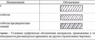
In drawing diagrams, indicating the material of the product and structure, conventional images are used, which are established by GOST 2.306-68. Hatching of concrete in the drawing is necessary in order to clarify which material is used, in particular, for similar structural elements. In addition to the schematic drawing, an explanatory inscription is written. Draw the document using a pencil using thin lines with different inclinations, distances and intersections of strokes.
View "GOST 2.306-68" or
Concept, features and system of information sources
Hatching is a symbolic symbol for building materials. Most often used when working with concrete. The drawing is drawn with a pencil and consists of dots, lines, and strokes intersecting or located at a certain distance. Schemes are used in most construction projects. However, there are features:
- if necessary, shading may not be created at all or may be created partially to highlight individual objects;
- If necessary, additional drawings with explanations are used for materials that are not provided for in the standard.
In construction, there are three systems of markings based on shading:
- GOST 3455 - 59;
- GOST 2.306 - 68;
- GOST R 21.1207-97.
Consider in detail each type, which has its own characteristics of applying symbols.
Standard GOST 3455 - 59
This template was used from January 1, 1959 to January 1, 1971. Its well-known title was “Drawings in mechanical engineering. Hatching in sections and sections.” The notation system was as follows:
- metal – designation in the form of oblique strokes between which there is an equal interval;
- other non-metallic objects - left and right inclined lines intersecting at right angles;
- tree: pattern of a sectional section - an image similar to the texture of larch; cross-section drawing - an image of cracks, as well as rings of a tree trunk;
- unreinforced concrete - schematic drawing of sand gravel;
- reinforced concrete – image of sand gravel, oblique strokes;
- brick - intersecting dotted and solid lines at an angle;
- glass - three types of strokes, between which there are vertical and horizontal intervals;
- liquid solution - designation by hatching, which is applied horizontally at tapering intervals;
- soil - a sandography pattern combined with three intersecting horizontal and vertical lines.
Return to contents
Standard GOST 2.306 - 68
To replace the symbol system that was canceled in 1971, GOST 2.306 - 68 was introduced. It is distinguished by its severity and lack of artistic effects. The newly introduced sections are as follows:
- tree - arcs of the same radius at intervals;
- stone of natural origin - dotted lines at an angle;
- ceramics or silicate - two groups of strokes that are separated by wide intervals;
- concrete – dotted lines at an angle;
- ground - three strokes united in a group, separated by gaps.
In addition, the necessary requirements of this standard are:
- if the line drawings of different materials are similar, they should be signed with an explanation;
- this standard does not cover reinforced concrete material - there is a GOST 21.107-78 template for it;
- façade materials are not depicted in full; small areas along the contour are sufficient.
With the introduction of this standard, the following application rules are set for the diagrams:
- oblique hatching is applied, as a rule, at an angle of 45 degrees relative to the base;
- when oblique lines coincide with contour or axial lines, an angle of 30 or 60 degrees is used for the former;
- the slope of the lines indicating one object must be the same;
- objects whose areas are shown in the drawings using narrow sections are hatched only at the ends and in small areas along the entire length;
- designation of very narrow parts - filled lines with small gaps between adjacent planes;
- a section of a small area is indicated by hatching like metal or is not hatched at all with certain marks;
- the inclination of oblique hatching lines on adjacent planes should be different;
- other rules defined by this standard.
Return to contents
GOST R 21.1207-97
As we have already indicated above, due to the lack of a system for diagrams of reinforced concrete structures in the GOST 2.306 - 68 standard, the need arose to create the GOST R 21.1207-97 standard. This template is most often used in road construction. In this document, a special place is mentioned, along with such materials as asphalt and soil, the following are mentioned:
- concrete - dotted lines;
- reinforced concrete - alternating continuous and interrupted lines;
- reinforced concrete with stressed reinforcement (heated or stretched reinforcement with enhanced bending properties) - alternating two solid and one dotted line.
Return to contents
Hatching of concrete on drawings (symbol)
3. Expanded steel
4. Masonry of building and special bricks, clinker, ceramics, terracotta, artificial and natural stones of any shape, etc.
1. (Deleted, Amendment No. 1).
2. To clarify the type of material, in particular, materials with the same type of designation, the graphic designation should be accompanied by an explanatory inscription in the drawing field.
3. In special construction design drawings for the reinforcement of reinforced concrete structures, designations according to GOST 21.501 should be used.
4. The designation of the material on the view (facade) is allowed not to be applied completely, but only in small areas along the contour or spots inside the contour.
5. Oblique parallel hatching lines should be drawn at an angle of 45 ° to the contour line of the image (Fig. 2 a) or to its axis (Fig. 2b), or to the lines of the drawing frame (Fig. 2).
If the hatch lines attached to the lines of the drawing frame at an angle of 45° coincide in direction with the contour lines or center lines, then instead of an angle of 45°, an angle of 30° or 60° should be taken (Fig. 3 and 4).
Hatch lines should be drawn with an inclination to the left or right, but as a rule, in the same direction on all sections belonging to the same part, regardless of the number of sheets on which these sections are located.
(Changed edition, Amendment No. 1).
6. The distance between parallel straight hatching lines (frequency) should, as a rule, be the same for all sections of a given part performed on the same scale and is selected depending on the hatching area and the need to diversify the hatching of adjacent sections. The specified distance should be from 1 to 10 mm, depending on the hatching area and the need to diversify the hatching of adjacent sections.
(Changed edition, Amendment No. 2).
7. Narrow and long cross-sectional areas (for example, stamped, rolled and other similar parts), the width of which in the drawing is from 2 to 4 mm, may be completely hatched only at the ends and at the contours of the holes, and the remaining cross-sectional area - in small sections in several places (Fig. 5 and 6). Glass hatch lines (Fig. 7) should be drawn with an inclination of 15-20 ° to the line of the larger side of the section contour.
8. Narrow cross-sectional areas, the width of which in the drawing is less than 2 mm, may be shown blackened, leaving gaps between adjacent sections of at least 0.8 mm (drawings 8, 9).
In construction drawings, it is allowed to designate any material as metal on sections of a small area or not to use the designation at all, making an explanatory inscription in the drawing field.
9. Designation specified in paragraph 3 of table. 1, and the designation of the backfill in the cross-section is done by hand.
(Changed edition, Amendment No. 1).
10. For adjacent sections of two parts, you should take the slope of the hatching lines for one section to the right, for the other - to the left (counter hatching).
When shading “in a cage” for adjacent sections of two parts, the distance between the hatch lines in each section should be different.
In adjacent sections with hatching of the same slope and direction, you should change the distance between the hatching lines (Fig. 10) or shift these lines in one section relative to another, without changing the angle of their inclination (Fig. 11).
Download collections of blocks in AutoCAD – StroyMetProekt
Home » Tutorial » AutoCAD training » Download block collections in AutoCAD
— The collection of AutoCAD blocks “Bolts, nuts, washers 2D and 3D” contains:
- Bolts in AutoCAD with hexagonal head (GOST 7805-70, 7798-70)
- Bolts in AutoCAD with a hexagonal reduced head (GOST 7808-70, 7796-70)
- AutoCAD hex nuts (GOST 5927-70)
- Low hex nuts in AutoCAD (GOST 5929-70)
- AutoCAD hex nuts with reduced wrench size (GOST 2524-70)
- AutoCAD hex nuts low with reduced size (GOST 2526-70)
- AutoCAD washers (GOST 11371-78)
- Enlarged washers AutoCAD (GOST 6958-78)
- Reduced AutoCAD washers (GOST 10450-78)
The library of AutoCAD blocks “Recreation Area” contains more than 150 objects. Here you will find sets of various blocks in .*dwg format, such as: AutoCAD simulators, musical instruments (pianos, grand pianos), elements for arranging a yard (top view, side view).
All these objects will help you quickly arrange a yard in AutoCAD and rooms intended for relaxation and entertainment.
If you need a staircase in AutoCAD, then in this file you will find 25 high-quality models in *dwg format, saved for the 2007 version of the program. The block collection contains the following objects:
— AutoCAD staircases (spiral, straight, corner, curved);
— passenger elevator AutoCAD;
— staircase nodes in AutoCAD.
Therefore, if you don’t know how to draw a staircase in AutoCAD, then just use a ready-made library.
Here you can download AutoCAD blocks "People and Animals". More than 200 models for free. In this collection you will find:
— drawing of a person in AutoCAD (top view, side view, frontal view)
— silhouette of a person in AutoCAD, as well as silhouettes of various animals;
— a set of 3D people in AutoCAD.
Here you can download AutoCAD plumbing absolutely free!
A huge collection of blocks for AutoCAD “Plumbing” includes more than 1000 objects: bathtubs, sinks, toilets, showers and shower stalls, baths and many different accessories (top view, side view, front view) in *.dwg format (file for the 2007 version of the program) .
Now, on the Internet, you no longer need to spend hours searching for individual objects for dignity. nodes and enter queries in a search engine, such as “download AutoCAD plumbing blocks”, “AutoCAD for plumbers” or “where is plumbing in AutoCAD”. No more dubious sites! Everything in one file. By the way, I myself use it all the time when I create commercial projects.
Therefore, for my subscribers, I have created the “Plumbing for AutoCAD” library, which you can download for free by clicking on the button below.
AutoCAD Electrical blocks will help you quickly assemble any electrical circuits in AutoCAD. Download a free set of AutoCAD blocks consisting of the following files:
— analog integrated circuits (19 objects);
— CMOS integrated circuit (25 objects);
— collections of AutoCAD blocks “Electrics” (24 objects);
— AutoCAD file “Electrical elements” (20 objects).
In this collection you will find car blocks for AutoCAD (side view, top view, as well as 3D models). AutoCAD cars are presented in a huge range: cars, heavy equipment, trains, tanks and much more.
In the collection you will find decorative and architectural elements, side views and 3D models. Original and interesting floral ornaments (patterns) in *.dwg format made with 2D lines will allow you to quickly create fancy 3D shapes for forged fences.
In the collection of household and office equipment you will find televisions, computers, servers, telephones, stoves, refrigerators, washing machines, etc. There are 2D and 3D objects
The collection of blocks “Trees for AutoCAD” contains a huge set of objects of various vegetation in plan, side view, 3D models, as well as many color cliparts
The "Signs in AutoCAD" block collection contains the following files:
- Fire hydrant sign_(PG)
- Road signs AutoCAD (traffic)
- Safety signs_(TB) and fire safety_(PB)
- Topographical signs for Autocoad
Description
Fire safety signs comply with NPB 160-97 for drawing up plans for evacuation of people in case of fire.
The drawing of a fire hydrant sign has been developed in accordance with GOST 12.4.009-83 “Fire fighting equipment for the protection of objects” and GOST 12.026-76* “Signal colors and safety signs” and is intended for use as a sample when writing inscriptions on sign signs.
AutoCAD road signs in *.dwg format are saved for the 2006 version of the program.
Such symbols for AutoCAD will help save you a lot of time!
In the collection you will find numerous options for kitchen furniture, household appliances, dishes (both 2D objects and 3D).
The AutoCAD "Furniture Blocks" collection contains a huge number of objects for the living room and bedroom: tables, chairs, beds, sofas, wardrobes, bedside tables and much more.
In the collection you will find AutoCAD blocks such as lamp posts, chandeliers, table lamps, floor lamps, etc. (2D and 3D objects are present).
The AutoCAD "Windows and Doors" library contains a huge selection of windows, stained-glass windows, entrance and interior doors of various sizes and configurations (2D, 3D, plan and front)... Now you don’t have to re-draw AutoCAD windows or doors every time for each project.
I collected the collection “Hatching for AutoCAD” (Hatching for AutoCAD). You can download hatching for AutoCAD by clicking the “Download” button.
The collection includes more than 1000 hatches.
The archive contains the following types:
— shading of concrete in AutoCAD;
— AutoCAD tree hatching;
— AutoCAD glass shading;
— hatching for AutoCAD geology (geological hatching for AutoCAD);
— shading of bricks in AutoCAD, etc.
In the pipes and fittings collection you will find dynamic blocks for AutoCAD of fittings and pipes. Now the question of how to draw a pipe in AutoCAD will no longer bother you.
Don't forget to share this collection with your friends!
- 3D Fountain
- 3D Rack
- 3D Ratonda
- 3D Bench, trash can and lantern
- 3D Armchairs in the waiting room
- 3D Port cranes
- 3D Playground
- 3D gazebo polygonal
- 3D gazebo square
Features: - All blocks have hidden attributes for automated creation of specifications in accordance with GOST 21.110-2013 - Many blocks are dynamic, with the ability to select a model, manufacturer, configuration, etc.
— Annotative text style is used, be careful about scale!
Also in the library there is a minimum of blocks necessary for a technologist: - Household appliances and furniture - Dynamic blocks of doors, windows (not GOST ones, since I only need the dimensions of openings for work) - Annotative markers of section, view, linear break, elevation marks, etc. — Plumbing — Stamp according to GOST R 21.1101-2013, all paper formats (see on sheet)
— Electrical small items (sockets, switches, indicators, etc.)
Road signs in one file according to GOST 51289. With changes 1,2,3.
- Dynamic blocks of bolts, washers and nuts.
- Regular
- Bolts GOST 7798-70
- Nuts GOST 7798-70
- Washers GOST 11371-78 Made both individually and as part of a package B-Sh-||-Sh-G-G
- High strength
- Bolts GOST R 52644-2006
- Nuts GOST R 52645-2006
- Washers GOST R 52646-2006 Made as part of the B-Sh-||-Sh-GS package Saved in ACAD2007
- Scales VUS 150
- Scrubber
- Juicer
- Kettle
- Shocker Abbot
Source of this material: https://autocad-specialist.ru
stroymetproekt.ru
What is shading on a plane?
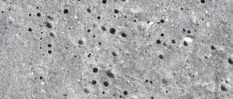
For easy reading of the technical drawing information, parts are indicated in sections. They display what exactly is in the cutting plane of the product, so that the elements are easily and simply distinguished and recognized for all areas of construction. Hatching of reinforced concrete and its parts is carried out with an inclined sand-gravel landscape 0.3 mm thick. For metallic materials, lines are drawn at equal distances. Non-reinforced concrete is indicated in the diagram as a sand-gravel pattern. Narrowed areas are shown blackened. The symbol for concrete in the drawings is strokes that are made intermittently and at an angle. Parallel lines are drawn of the same type and scale from 1 to 10 mm.
To depict such material on paper, it is customary to use a sand-gravel landscape tilted at a certain angle.
Creating a Design Route Profile
Before constructing the design profiles, three types of profiles were created (for the existing section of M-10, for the section of the ramp to the substation, and for the section of the ramp to the gas station). Command Profile Creation Tool
We created three design profiles based on the existing terrain.
Then the Profile Similarity
raised the design profiles 16 cm up.
This is necessary to justify the scope of work for the prepared structures. It is necessary to mill the existing pavement by 10 cm and install three layers of asphalt concrete with a total thickness of 26 cm.
As indicated in the drawings: design features
Graphically designate drawing sections for different types of materials so that the builder understands what material the component part or product was made from. According to GOST, lines in an official drawing document must be drawn at an angle of 45 and 90° to the axis and frame of the entire drawing. Shade parts of structures and their parts in one direction for a specific product. If the hatching line coincides with the contour, then change the angle of their execution - 30-60°. Sectional figures give a general idea of what the elements are made of, and therefore additionally describe the material itself. The full characteristics are written in the specifications under the drawing or statements.
The correct angle of graphic filling of the material section should be equal to 45 degrees relative to the axis and frame of the entire drawing.
In addition to the basic requirements, it is worth considering:
- The frequency of the lines of the main element. If it coincides with another, additional explanation must be given depending on the location.
- For reinforced concrete parts of the structure, there is a separate type of design documentation GOST 21.107-78 “Conventional images of elements of buildings and structures.”
- The lines are drawn strictly to the left or to the right.
- Hatching of concrete is done by hand (except for strips with a straight direction).
- In a cage (insulation), intersecting sections of 2 parts are schematically depicted, which need to be drawn at a distance and these lines must be made different.
- It is necessary to use construction shading for construction and structural drawings of buildings with reconstruction or at the construction stage.
- Narrow cuts (from 2 to 4 mm) are partially painted over, along the edges in convenient places for perception.
- The material of the façade is depicted in small sections along the contour of the part.
Explanation of the basics of the regulatory document GOST 21.107-78
The standard has been cancelled, but shading is still used. The main conclusions regarding reinforced concrete products are as follows:
- prestressed reinforced concrete is depicted in 2 straight lines, the next with a dotted line;
- concrete with reinforcement is displayed in alternately drawn lines, broken and continuous;
- unreinforced is hatched dotted.
Each type of material is depicted in a specific way.
This means that in a monolithic slab on a large scale in the drawing, the section with the arrangement of reinforcing elements (schematically done in circles) and concrete without reinforcement is shaded as concrete. In the cross-section of the entire building, the reinforcement component on the slab section is not shown, being performed as a reinforced concrete part (solid and dotted alternately). It is not customary to shade metal, that is, the place where the reinforcement of parts is shown is not shaded. Designation lines and reinforcement cannot be done in the same type, since when reading the document, the shading is difficult to make out.
Cross-section profiles of the subgrade
To perform specifications, it is necessary to make transverse profiles of the subgrade. Using the program, you can quickly create cross-section lines (by pickets, by pickets with steps, arbitrarily pointing to the route). Then all that remains is to create several types of cross sections using the Section Output Wizard and at the end simply specify the insertion point of the section views (cross sections) in the drawing.
Cross sections
Standards for developers and manufacturers
Before the advent of GOST 2.306-68, the current drawing standards were GOST 3455-59 and GOST 11633-65, but, in fact, they were duplicates of each other. Sources of regulatory documentation for the correct design of drawings:
- Image of drawing fonts. — GOST 3454–59.
- Drawing lines - GOST 3456–59.
- Hatching of elements of various structures in sections - GOST 3455–59.
- Conventional graphic images of building elements and materials - GOST 2.306-68.
- Dimensions in the drawing diagram - GOST 3458–59.
To correctly execute the drawing, you must use the symbols specified in the regulatory documentation.
It should be noted that shading of concrete and concrete connections with steel reinforcement in a specially developed computer drawing design system in the AutoCAD program differs from hand-made drawings. They use a special fill of elements to fill the selected area according to an existing pattern.
The rules provided for by the basic requirements of the standards must be followed. In order to correctly apply and understand the indicated dimensions, you need to study the conventions that are established by GOST 2.307-68. It is worth considering that inscriptions with explanations are applied to the drawing if different types of concrete and structures made from it are used (precast, monolithic, prestressed, etc.). On construction drawings for concrete elements with a homogeneous component, panels, wall blocks and elements that do not need to identify the composition, designations are not used.
Technical task
The customer was tasked with carrying out design work in the city of Vyshny Volochek, Tver Region, the length of the highway is 510 m. It was necessary to produce a set of drawings of the AD brand that meets Russian standards.
In accordance with the terms of reference, a number of design works had to be completed. In particular, design:
- milling of existing coating; strengthen the existing pavement with asphalt concrete, h=0.26 m;
- transitional express lane (TSL) for a category II road, new road pavement on the TSL, h=1.26 m;
- slopes with a laying ratio of 1:4; berms for road signs and lighting poles;
- strengthening roadsides; strengthening slopes by sowing perennial grasses.
To solve the problem, the AutoCAD Civil 3D 2010 software package was chosen.
Hatching concrete according to GOST standards
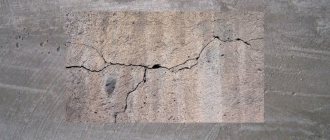
How is reinforced concrete shading done correctly in drawings? Are there any standards establishing the way of designing sections and types of building structures? We have to find answers to these and some related questions.
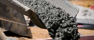
This is what concrete looks like in cross section. How is it indicated on the drawings?
How to make thread curtains with your own hands
Thread curtains in the interior were once a huge success, but then their popularity gradually faded. It is safe to say that today thread curtains are experiencing a second boom in popularity. They are ways to radically change the idea of curtains, so owners who love original ideas and a non-standard approach often use them to decorate rooms.
Thread curtains mean weightlessness and a unique appearance, lightness and a wide range of uses in the interior.
Thread curtains bring a fairy tale, dream and fantasy into the house.
Thread curtains can be called immigrants from the East. It was there that this option was invented for decorating a window into which the sun constantly shines. The products protected from scorching rays, but at the same time did not prevent the penetration of fresh air inside. These are not the only advantages of such products:
- There is a wide variety in shades and colors. These curtains are ideal for window decoration in a bedroom, nursery, or living room;
- You can independently complement the curtain with some interesting decorative elements: pebbles and beads, seed beads, glass beads;
- You don’t need to think long about how to tie such a curtain. It attaches quickly and looks equally beautiful in any version.
Spiral
Each thread of such a product will be twisted like a spiral, which is where this decor option gets its name. Manufacturers guarantee that the threads will not unwind if used correctly.
Rainbow and Rain
The Rain collections are not like other thread curtains because they have a unique, elegant shine. This effect is achieved due to the fact that thin strips of lurex are woven into the threads. The thickness of each thread is no more than three millimeters. The height can be adjusted freely. The Rainbow collection is distinguished by a soft and smooth flow of one color into another. Both materials of the same color range and completely different shades can be used.
Investigation
Like the reader, the author of the article was once a schoolchild and, among other things, attended drawing classes. Hatching of cuts was still in use then; I remember some designations especially well. Among them is a way to designate concrete, which required some artist’s skills: it should have been depicted as something like a landscape of a sand-gravel quarry, made by the hand of Ostap Bender (see also the article “Freezing temperature of concrete - important information for builders”).
As it turned out much later, the drawing teacher simply did not know about the new standard adopted after he received higher education and taught schoolchildren the same way he himself was taught.
GOST 3455 - 59
The standard came into force on January 1, 1959 and was canceled exactly 12 years later, on January 1, 1971. Its title is “Drawings in mechanical engineering. Hatching in sections and sections.”
General information
GOST shading of materials is a symbol. Using shading on the diagram, you can determine the type of building material. This is required for convenience during the construction of objects for various purposes.
Concrete is shaded from several constituent elements that are located at some distance from each other, and the lines and strokes used may intersect.
Such drawings are used during the construction of many construction projects. However, there are some nuances that must be taken into account:
- you can additionally draw up the required number of drawings and indicate explanations for individual building materials that were not taken into account during the creation of the standard;
- taking into account GOST, the designation of concrete on the drawings may be absent if this is not necessary, or it may be partially indicated - to highlight a specific object.
Today, several established templates are used in construction: GOST 3455–59, GOST 2306−68, GOST R 21.1207−97.
Designation according to GOST 3455–59
This established template was created in the 60s, it began to be used on construction diagrams from 02/01/1962. GOST was valid until 02/02/1973. It describes drawings for mechanical engineering. The conditional values were as follows:
- non-metallic building materials - marked in the form of lines inclined to the left or right at an intersection of 90 degrees;
- metal - marked with oblique lines, maintaining the same distance;
- liquids - vertical dotted lines with tapering intervals;
- rings and cracks - a longitudinal section was used for symbolic designation;
- wood - designations were used taking into account the characteristics of wood;
- solutions were marked with horizontal hatching, and the gaps were made narrow;
- plywood - sectional section;
- unreinforced reinforced concrete structures were made in the form of sand and gravel;
- expanded clay concrete - sand gravel was applied, additionally 3 crossed lines were used, which are located in different directions;
- glass - indicated on the diagrams using strokes of three varieties and different intervals;
- reinforced concrete - oblique strokes with a sand-gravel pattern;
- brickwork - two types of lines intersecting at an angle were used.
Processing of engineering survey data
Before the start of work on designing the reconstruction of the existing junction, a topographic survey of the area was received from the survey department, created in CREDO in *.dwg format with subsequent editing of the triangulation in GeoniCS.
Initial topographic survey in CREDO
For project flexibility and optimal work with related departments, it was decided to use the functionality of quick links to AutoCAD Civil 3D data. A data storage folder was created, after which the surface was edited using AutoCAD Civil 3D functions for working with surfaces. The program very successfully implements a package of tools that allows you to significantly reduce the time needed to edit surfaces ( Delete face, Move edge, Change point height
).
Then the surface display style was configured (the contour pitch was set for M 1:500, the color of the contours, the thickness), which was saved in the basic AutoCAD Civil 3D template.
As a result, an edited existing digital terrain model (DTM) was obtained.
Topographic survey edited in AutoCAD Civil 3D
Difference GOST 2.306−68
As already indicated, the previous system was abolished in 1973. This standard has been modified by new designation elements.
The main difference between the new shading of reinforced concrete according to GOST is the mandatory compliance and rigor of the standard. This established template has been simplified. The new system did not have any special effects, everything was clear and precise. The main changes were as follows:
- stones - depicted in the diagram as an inclined dotted line;
- tree - designated using identical arcs located at the same distance;
- ground - three strokes were used, representing a group with small intervals;
- hatching of concrete according to GOST was done using dotted lines, observing a certain slope;
- ceramic building materials and silicate - were indicated by elements that consisted of several groups, and there was a significant distance between the lines.
New graphic elements make it possible to indicate on the drawings the required building materials during the construction of buildings and other structures. This is convenient both during the production of individual elements and during the creation of various objects.
The marks are drawn with thin lines, drawing them in the required order and at a given distance. Within one schematic drawing, symbols of metal products should stand out from other building materials. Therefore, more space must be left between the lines when specifying these elements.
Intersection design
In the example given, we will consider the intersection of a highway with two secondary roads (exits). This will create two intersections. AutoCAD Civil 3D provides convenient functionality for Creating an Intersection
.
There are two main ways to build intersections, which we will consider.
To build an intersection in semi-automatic mode, the first method is suitable. Here, before building an intersection, you need to create and configure its seven main structures:
- edge at the turn;
- the main road;
- main road on the left with carriageway;
- main road on the right with carriageway;
- secondary road;
- minor road on the left with carriageway;
- minor road on the right with a carriageway.
After creating seven structures, the Intersection
and in the Intersection Wizard, all the necessary elements of this intersection were configured (structures, turning radii, widenings). As a result, we received an intersection in the form of a corridor. This corridor-intersection can be built into the main M-10 corridor. We do the same for the second exit from M-10. If you have a complex design, then when building a road in semi-automatic mode, you may need to go to
Corridor Settings
and in the Goals tab, delete or reconfigure the goals, then everything will look very beautiful, as was intended in the design of the exit from M-10.
The second method is more labor-intensive, but it allows you to understand the basic principle of constructing an intersection of any configuration, and indeed any intersection in AutoCAD Civil 3D. And the method is labor-intensive because it will have to perform a larger number of operations.
For example, the constructed main road corridor will need to be divided into three areas (before the intersection, intersection, after the intersection, taking into account turning radii).
In the areas that appear, in the main road corridor settings you need to specify pre-created structures that will be in these areas. After linking the design elevations at the road intersection (along longitudinal profiles), a second secondary road corridor should be created.
Since the corridors will intersect, there will be no mates between the roadway and the shoulders, therefore, these mates need to be defined. You can draw mates using polylines and then use the AutoCAD Civil 3D Create Alignment from Objects
turn a polyline into a route. You can immediately draw routes with specified turning radii. In my opinion, it is more convenient to design with a polyline, since a polyline is a “smart line”. It can be used for different purposes during the design process.
In the properties of the secondary road corridor, you need to add left and right turn areas using the Add base area
and insert new routes (mate routes), as well as structures on the mates, indicating the beginning and end of the mate. In addition, you will have to edit the target offset and target grade along the added alignments to ensure that the structures span the entire intersection area. The result was two corridors. The first corridor of the main road is without an intersection. The second corridor of the secondary road has an intersection. And only after this can the volume of work be calculated automatically on two roads separately.
Features of GOST from 1973
There are also other features of the standard. These rules are expressed in the following points:
- explanations must be provided;
- if there is a similarity in the drawing of various elements during which various materials are described, then one cannot do without auxiliary information;
- façade building materials are not indicated in full; in this case, it is only necessary to partially indicate the outline;
- features of shading of building material on the diagram are indicated in GOST 21 .107−78;
- There are no designations for reinforced concrete structures in the standard, so a special template was developed for them.
There are also certain rules that the 1973 standard provides for. Hatching of concrete is carried out in this way:
- Small sections are marked with strokes. This designation is similar to the description of a metal.
- Lines that need to be drawn at an angle must be drawn with a clear slope of 45 degrees. The angle must be determined taking into account the landmark not only of the diagram itself, but also in compliance with the contour of the image.
- In adjacent planes, lines must be drawn at different angles.
- Hatching is left-handed or right-handed, but in one design the angle for the sections should be the same.
- Long narrow cuts do not have to be completely shaded; shading can be only along the edges or in several areas that are chosen in any form. Sections with a thickness of no more than 3 mm are completely shaded.
The rules provided for by the standard must be complied with.
Latest innovations
The GOST of 1973 had a significant drawback: it did not have a standard for describing reinforced concrete. This explains the need to develop GOST R 21.1207−97. This flaw was corrected in the installed template and the necessary designation was added.
Most often, this standard is used when road work is carried out. In addition to asphalt, as well as other building materials, in this template a special place is given to the following points:
- reinforced concrete, which is equipped with stressed reinforcement - 2 solid lines are used alternately, followed by one dotted line;
- reinforced concrete - solid and broken lines are drawn in turn;
- The shading of concrete in the diagram is indicated by a dotted line.
The main task when using reinforced concrete shading is the need to show, with the help of design drawings, the structure that needs to be implemented. Conventions help greatly in accomplishing this task.
Today, two main established templates are considered valid; both GOST standards are used in the construction industry and mechanical engineering. These templates enable builders to quickly determine the required building materials during the construction of various structures.
3D model of the designed road
After working out all the elements of road design (DEM, alignment, surface profile, profile type, design profile), you can begin to develop a future 3D model of the reconstructed section of the M-10 federal highway. During my time working in AutoCAD Civil 3D, two main methods for designing 3D models have been developed:
- a method for constructing a 3D model of a road along a corridor;
- a method of constructing using characteristic lines and profiling objects.
It should be noted that each of the above methods takes some time, but still the process is carried out much faster than simply using AutoCAD or even using a drawing board with a pencil! Let's talk about each of these methods in more detail.
With the first method, you will have to deal with very important elements of the corridor - goals and structures. As a result, if you choose the right goals for the corridor elements (alignments, displacement routes, profiles along them) and create a pre-thought-out design from the tool palette, then as a result you will get a beautiful and dynamic 3D model of the corridor.
With the second method, it is necessary to spend time constructing characteristic lines with elevation marks, as well as constructing slopes using grading objects. The disadvantage of this method is that it will not be possible to obtain the volume of work for the construction of the designed site using AutoCAD Civil 3D.