Types and features of bricks
A large number of different materials are used in the construction process.
And so that craftsmen can distinguish them in the drawings, various symbols have been introduced. The shading of the section shows graphically what material is used. Of course, the most popular building material is brick. The shading of the brick in the drawing consists of inclined lines, the distance between which is the same. GOST requirements should be taken into account when creating drawings. Moreover, such shading is used for any brick, regardless of the types, of which there are many. Let's talk about some of them.
Concrete marking explanation
Marking concrete and products made from it: learning to read symbols
In our article we will provide information about the most common designations, as well as a number of tips on the use of certain materials.
Different tasks require different solutions
Concrete and its typesMaterial grade
The grade of concrete is the main characteristic of a specific ready-made and prepared concrete mixture, which determines the quantitative ratio of the main components (cement, sand, crushed stone and water), as well as the scope of application of this building material.
Designation of concrete grades
Additional characteristics, the value of which depends on the brand of concrete and the amount of additives added, are: water resistance, frost resistance and stackability.
GOST 2.306-68* ESKD. Designations of graphic materials and rules for their application on drawings.
UNIFIED SYSTEM OF DESIGN DOCUMENTATION
DESIGNATIONS OF GRAPHIC MATERIALS AND RULES FOR THEIR APPLICATION ON DRAWINGS
IPC PUBLISHING HOUSE OF STANDARDS Moscow
Unified system of design documentation
DESIGNATIONS OF GRAPHIC MATERIALS AND RULES FOR THEIR APPLICATION ON DRAWINGS
Unified system for design documentation. Graphical designations of materials and rules for their representation
Date of introduction 01/01/71
1. This standard establishes graphic designations of materials in sections and on facades, as well as rules for applying them to drawings of all industries and construction.
(Changed edition, Amendment No. 2).
la. The general graphic designation of materials in sections, regardless of the type of materials, must correspond to the following. 1 a.
(Introduced additionally, Amendment No. 1).
2. Graphic designations of materials in sections, depending on the type of materials, must correspond to those given in table. 1 .
It is allowed to use additional designations for materials not provided for in this standard, explaining them in the drawing.
1. Metals and hard alloys
2. Non-metallic materials, including fibrous monolithic and slab (pressed), with the exception of those indicated below
4. Natural stone
7. Glass and other translucent materials
9. Natural soil
1. Composite materials containing metals and non-metallic materials are designated as metals.
2. The graphic designation of paragraph 3 should be used when there is no need to indicate the direction of the fibers.
3. The graphic designation of clause 5 should be used to designate brick products (fired and unfired), refractories, building ceramics, electrical porcelain, cinder blocks, etc.
(Changed edition, Amendment No. 1, 2).
3. Install the following designations for mesh and backfill made of any material (in cross-section), indicated in the drawing. 1 .
a - mesh; b – backfill
2. Corrugated steel
3. Expanded steel
4. Masonry of building and special bricks, clinker, ceramics, terracotta, artificial and natural stones of any shape, etc.
1. (Deleted, Amendment No. 1).
2. To clarify the type of material, in particular, materials with the same type of designation, the graphic designation should be accompanied by an explanatory inscription in the drawing field.
3. In special construction design drawings for the reinforcement of reinforced concrete structures, designations according to GOST 21.501 should be used.
4. The designation of the material on the view (facade) is allowed not to be applied completely, but only in small areas along the contour or spots inside the contour.
5. Oblique parallel hatching lines should be drawn at an angle of 45 ° to the contour line of the image (Fig. 2 a) or to its axis (Fig. 2b), or to the lines of the drawing frame (Fig. 2).
If the hatch lines attached to the lines of the drawing frame at an angle of 45° coincide in direction with the contour lines or center lines, then instead of an angle of 45°, an angle of 30° or 60° should be taken (Fig. 3 and 4).
Hatch lines should be drawn with an inclination to the left or right, but as a rule, in the same direction on all sections belonging to the same part, regardless of the number of sheets on which these sections are located.
(Changed edition, Amendment No. 1).
6. The distance between parallel straight hatching lines (frequency) should, as a rule, be the same for all sections of a given part performed on the same scale and is selected depending on the hatching area and the need to diversify the hatching of adjacent sections. The specified distance should be from 1 to 10 mm, depending on the hatching area and the need to diversify the hatching of adjacent sections.
(Changed edition, Amendment No. 2).
7. Narrow and long cross-sectional areas (for example, stamped, rolled and other similar parts), the width of which in the drawing is from 2 to 4 mm, can be completely hatched only at the ends and at the contours of the holes, and the rest of the cross-sectional area - in small sections in several places (Fig. 5 and 6). Glass hatch lines (Fig. 7) should be drawn with an inclination of 15-20 ° to the line of the larger side of the section contour.
(Changed edition,
Amendment No. 4 )
8. Narrow cross-sectional areas, the width of which in the drawing is less than 2 mm, may be shown blackened, leaving gaps between adjacent sections of at least 0.8 mm (drawings 8, 9).
In construction drawings, it is allowed to designate any material as metal on sections of a small area or not to use the designation at all, making an explanatory inscription in the drawing field.
9. Designation specified in paragraph 3 of table. 1, and the designation of the backfill in the cross-section is done by hand.
(Changed edition, Amendment No. 1).
10. For adjacent sections of two parts, you should take the slope of the hatching lines for one section to the right, for the other - to the left (counter hatching).
When shading “in a cage” for adjacent sections of two parts, the distance between the hatch lines in each section should be different.
In adjacent sections with hatching of the same slope and direction, you should change the distance between the hatching lines (Fig. 10) or shift these lines in one section relative to another, without changing the angle of their inclination (Fig. 11).
11. For large cross-sectional areas, as well as when indicating the soil profile, it is allowed to apply the designation only at the contour of the section with a narrow strip of uniform width (Fig. 12).
(Changed edition, Amendment No. 1).
1. DEVELOPED AND INTRODUCED by the Committee of Standards, Measures and Measuring Instruments under the Council of Ministers of the USSR
V.R. Verchenko, E.A. Panfilov, Yu.I. Stepanov, Ya.G. Old-timer, B.Ya. Kabakov, L.V. Matveev, N.I. Ermin, V.N. Vzorov, M.G. Aranovsky
2. APPROVED AND ENTERED INTO EFFECT by the Decree of the Committee of Standards, Measures and Measuring Instruments under the Council of Ministers of the USSR in December 1967.
4. Instead of GOST 3455-59 and GOST 11633-65
5. REFERENCE REGULATIVE AND TECHNICAL DOCUMENTS
Designation of the referenced technical document
6. EDITION (April 2000) with Amendments No. 1, 2, 3, approved in August 1980, September 1987, March 1989 (IUS 11-80, 12-87, 7-89)
Like the reader, the author of the article was once a schoolchild and, among other things, attended drawing classes. Hatching of cuts was still in use then; I remember some designations especially well. Among them is a way to designate concrete, which required some artist’s skills: it should have been depicted as something like a landscape of a sand-gravel quarry, made by the hand of Ostap Bender (see also the article “Freezing temperature of concrete - important information for builders”).
As it turned out much later, the drawing teacher simply did not know about the new standard adopted after he received higher education and taught schoolchildren the same way he himself was taught.
GOST 3455 - 59
The standard came into force on January 1, 1959 and was canceled exactly 12 years later, on January 1, 1971. Its title is “Drawings in mechanical engineering. Hatching in sections and sections.”
Question 5. Which hatchings in AutoCAD correspond to GOST?
There are a lot of hatches built into AutoCAD, but most often they use those that comply with GOST. Let's look at a few of them as examples.
For example, ANSI 36 is used for shading concrete.
ANSI 35 is used for shading in reinforced concrete.
For brick, ANSI 32 pattern shading is used.
To give the drawing clarity, sections (including sections included in the section) are hatched.
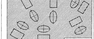
In accordance with GOST 2.306 - 68, graphic designations of materials in sections are established for various materials, some of which are shown in Fig. 253.
Rice. 253. Graphic designations of materials in sections
When shading metals, building bricks and some other materials, thin (from s/2 to s/3) parallel lines are used, which are drawn at an angle of 45° to the drawing frame, the image axis or the contour lines of this image. The distance between parallel straight hatching lines should, as a rule, be the same for all sections of a given part performed on the same scale and be selected in the range from 1 to 10 mm depending on the hatching area.
Narrow cross-sectional areas, the width of which in the drawing is equal to or less than 2 mm, are blackened, since it is difficult to apply shading on them (Fig. 254).
Rice. 254. Blackened narrow cross-sectional areas
Hatching of wood, plywood, glass and natural soil should be done by hand. Hatching with parallel straight lines can be conveniently done using a ruler and a square with angles of 45°.
Answer the questions
1. What line thickness is used for shading sections of metal parts?
Difference GOST 2.306−68
As already indicated, the previous system was abolished in 1973. This standard has been modified by new designation elements.
The main difference between the new shading of reinforced concrete according to GOST is the mandatory compliance and rigor of the standard. This established template has been simplified. The new system did not have any special effects, everything was clear and precise. The main changes were as follows:
- stones - depicted in the diagram as an inclined dotted line;
- tree - designated using identical arcs located at the same distance;
- ground - three strokes were used, representing a group with small intervals;
- hatching of concrete according to GOST was done using dotted lines, observing a certain slope;
- ceramic building materials and silicate - were indicated by elements that consisted of several groups, and there was a significant distance between the lines.
New graphic elements make it possible to indicate on the drawings the required building materials during the construction of buildings and other structures. This is convenient both during the production of individual elements and during the creation of various objects.
The marks are drawn with thin lines, drawing them in the required order and at a given distance. Within one schematic drawing, symbols of metal products should stand out from other building materials. Therefore, more space must be left between the lines when specifying these elements.
Parallel lines are made while maintaining equal intervals for sections of a certain part of structures that have the same scale. For different cross-sectional areas this step is 2−12 mm.
During the creation of the new shading system, the old GOST was canceled. The newly established template of 1973 indicates the same production stages as in GOST 1962. The first version of GOST is invalid.
In this case, the standard that was adopted in 1962 is reviewed for reference to other accepted established standards.
Latest innovations
The GOST of 1973 had a significant drawback: it did not have a standard for describing reinforced concrete. This explains the need to develop GOST R 21.1207−97. This flaw was corrected in the installed template and the necessary designation was added.
Most often, this standard is used when road work is carried out. In addition to asphalt, as well as other building materials, in this template a special place is given to the following points:
The main task when using reinforced concrete shading is the need to show, with the help of design drawings, the structure that needs to be implemented. Conventions help greatly in accomplishing this task.
Concept, features and system of information sources
Hatching in design and construction work is a symbolic designation of different types of building materials. Most often, shading is used in concrete work. Previously, a drawing was created in pencil using parallel or intersecting lines, strokes, and dots. Today, diagrams can be drawn using special computer programs, which speeds up and facilitates the process of creating drawings.
Some features of shading:
- If necessary, the symbol for concrete in the drawing may not be made or may be created partially for the purpose of highlighting specific objects.
- If there is a reason for this, additional drawings should be used with careful explanation regarding materials not included in the standards.
- The main systems of standards for designation in shading are the old GOST 3455-59 (not currently used in the form in which it is, since the next GOST added/changed the designations), GOST 2.306-68 (current version for designating different materials, sections), new GOST R 21.1207-97 (supplemented existing standards for the designation of concrete, reinforced concrete, etc., usually used in road construction).
Standard GOST 3455-59
This template was used from 01/01/1959 to 01/01/1971. The commonly used name of the standard was “Drawings in mechanical engineering. Hatching in sections and sections.”
Basic notation system (they are still used):
- Metal - draw with oblique strokes with equal intervals between them.
- Non-metallic products are lines slanted to the right/left that intersect at right angles.
- Wood - a cross section is indicated in the form of cracks and rings of a tree trunk, a lobar section is drawn in the form of an image reminiscent of the texture of larch.
- Non-reinforced concrete - a schematic drawing of sand gravel.
- Brick - solid and dotted lines that intersect.
As indicated in the drawings: design features
Graphically designate drawing sections for different types of materials so that the builder understands what material the component part or product was made from. According to GOST, lines in an official drawing document must be drawn at an angle of 45 and 90° to the axis and frame of the entire drawing. Shade parts of structures and their parts in one direction for a specific product. If the hatching line coincides with the contour, then change the angle of their execution - 30-60°. Sectional figures give a general idea of what the elements are made of, and therefore additionally describe the material itself. The full characteristics are written in the specifications under the drawing or statements.
The correct angle of graphic filling of the material section should be equal to 45 degrees relative to the axis and frame of the entire drawing.
In addition to the basic requirements, it is worth considering:
- The frequency of the lines of the main element. If it coincides with another, additional explanation must be given depending on the location.
- For reinforced concrete parts of the structure, there is a separate type of design documentation GOST 21.107-78 “Conventional images of elements of buildings and structures.”
- The lines are drawn strictly to the left or to the right.
- Hatching of concrete is done by hand (except for strips with a straight direction).
- In a cage (insulation), intersecting sections of 2 parts are schematically depicted, which need to be drawn at a distance and these lines must be made different.
- It is necessary to use construction shading for construction and structural drawings of buildings with reconstruction or at the construction stage.
- Narrow cuts (from 2 to 4 mm) are partially painted over, along the edges in convenient places for perception.
- The material of the façade is depicted in small sections along the contour of the part.
Explanation of the basics of the regulatory document GOST 21.107-78
The standard has been cancelled, but shading is still used. The main conclusions regarding reinforced concrete products are as follows:
- prestressed reinforced concrete is depicted in 2 straight lines, the next with a dotted line;
- concrete with reinforcement is displayed in alternately drawn lines, broken and continuous;
- unreinforced is hatched dotted.
Each type of material is depicted in a specific way.
This means that in a monolithic slab on a large scale in the drawing, the section with the arrangement of reinforcing elements (schematically done in circles) and concrete without reinforcement is shaded as concrete. In the cross-section of the entire building, the reinforcement component on the slab section is not shown, being performed as a reinforced concrete part (solid and dotted alternately). It is not customary to shade metal, that is, the place where the reinforcement of parts is shown is not shaded. Designation lines and reinforcement cannot be done in the same type, since when reading the document, the shading is difficult to make out.
Standards for laying aerated concrete
Aerated concrete is produced in the form of piece products:
- wall blocks;
- U-shaped blocks;
- aerated concrete lintels and partitions;
- floor slabs.
The laying of aerated blocks is carried out according to general rules, but taking into account the specific characteristics of the material. Reinforcing elements are used on the masonry itself and supporting structures under the ceilings. An adhesive or mortar connection is used for connection. The first option is more labor-intensive, but it ensures the absence of cold bridges that form on thick mortar joints. However, to ensure a thin seam (standard thickness is 2±1 mm), it is necessary to grind the surface of each row of masonry. This is a very labor-intensive procedure, but without it it is impossible to ensure fine-seam masonry.
Glue for aerated concrete is produced in the form of a dry mixture, which is mixed with water before use directly on the site. There is another option - polyurethane adhesive foam. It is more expensive, but provides a tighter connection and does not form cold bridges. Conventional mortar is used when laying the first row so that it is possible to level the masonry due to the thickness of the mortar layer. You can lay partitions made of gas blocks on it, which cannot form cold bridges. Before application, the surface of the material must be moistened so that moisture from the solution is not absorbed into the aerated concrete.
Laying of wall blocks is carried out with bandaging of vertical seams. The optimal option is to shift by half the length of the block, the minimum is by 10 cm. To make additional blocks, hand or electric tools are used.
Reinforcement
According to the requirements of the joint venture, masonry made of aerated concrete blocks must be reinforced at every meter of height. Depending on the size of the blocks, this is every third or fourth row. The procedure is performed in several stages:
- the surface of the row is polished in the same way as before laying the next row;
- two grooves are made along the edges (5-7 cm from the cut of the blocks). For this, a manual wall chaser is used. Groove depth - 2.5 cm;
- The grooves are filled with adhesive and a corrugated reinforcing bar with a diameter of 8 mm is immersed in them. The rod must be completely hidden in the groove;
- Apply an adhesive layer on top and lay the next row of blocks.
Before laying the floors, an armored belt is installed. This is a series of U-shaped blocks laid around the entire perimeter of external and internal load-bearing walls. It is a continuous closed tray, inside of which a reinforcement frame is installed in the form of a spatial lattice of 4 working rods. After this, the tray is filled with concrete flush with the edges and wait until the material hardens. Laying the floor and continuing work without waiting for the reinforced belt to gain structural strength is prohibited.
Reinforcement procedures cannot be ignored. This will cause cracks and subsidence of the material in the areas where the floors support. The result will be the destruction of aerated concrete at the most stressed points, which will sooner or later lead to the collapse of the building.
Technical drawing
Popular
Drawing Basics
Construction
Mechanical Engineering
Hatching in sections and sections is performed in the form of parallel straight lines drawn at an angle of 45° to the center line or contour line, taken as the main one. The slope of the lines can be either left or right; but for all cuts and sections related to the same part, hatching should be done with the lines sloping in the same direction.
Note: The thickness of the hatch lines is in accordance with GOST 3456-46.
When shading in sections and sections, the following conventions should be used:
For examples of the use and combination of symbols, see Fig. 45, 50, 51 and 52.
Notes.
1. The above symbols define this or that material only in general terms; all necessary data regarding materials must be placed in specifications, statements, etc.
2. Other materials can be indicated in sections and sections by hatching like “Metals” with an explanatory inscription directly next to the hatched surface (Fig. 51).
3. Metal gaskets and fills may be indicated in sections and sections, in addition to shading into the grid, also by shading according to the “Metals” type.
4. The following shading options are allowed:
In the same drawing, shading must be done either according to the indicated options, or according to the symbols of paragraph 2.
The symbols for wood and earth, as well as the circles for concrete, are done by hand. Glass can also be marked by hand.