Shrinkage of concrete
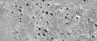
When mortars harden, their volume changes towards a decrease, which leads to the formation of cracks. The parameter depends on the brand of cement used, the amount of water in the mixture and the method of compaction. Methods have been developed to reduce shrinkage and prevent destruction of the concrete pad, but it is impossible to completely neutralize the process.
When the material is exposed to certain factors, it may change.
During the process of setting and hardening of concrete, the following shrinkage options can be distinguished:
- Plastic shrinkage of concrete . Occurs within 8 hours after pouring. After this period it is not taken into account. Its reason is the loss of water from the poured mixture. This problem occurs due to the release of water from the cement laitance through the formwork, base, and evaporation into the environment. To minimize this process, it is necessary to correctly install the formwork, waterproof it, arrange a cushion of lean concrete under the concrete element, and provide optimal conditions for setting and hardening of the mixture until it reaches critical strength (50-70% of the brand value). The higher the temperature and lower the relative humidity, the more often it is necessary to moisten the concrete element, especially in the first days after pouring. The maximum permissible value of linear plastic shrinkage is 4 mm per 1 meter. This process is primary and is reversible.
- Autogenous . It flows in young concrete until brand strength is achieved, which under standard conditions occurs at the age of 28 days. Typically, the linear change in dimensions is 1 mm per 1 m and is not taken into account in the construction of low-rise buildings. In large concrete elements it provokes the appearance of microcracks.
- Changes in the dimensions of mature concrete. Lasts for three to four months after pouring. In the future, if it is present, it proceeds extremely slowly. Previously, to ensure the strength of the structure, the foundation, poured using monolithic technology, stood for a long period - up to a year. Today, this problem is solved by using certain types of cement and the introduction of special additives, as well as through rational reinforcement.
Concepts of strength and class
Strength by grade was used before the introduction of European standards, and it designated average compressive strength. New SNiPs regulate classes of compressive-tensile strength.
Increase in strength
The concept of “class” means the resistance of the material, according to SP, to the axial compression of a concrete cube. The reference dimensions of the cube are 15 x 15 cm. Due to the uneven distribution of strength parameters throughout the material, the use of arithmetic average strength indicators is not recommended, since in a local area the objective strength may be lower.
The main characteristic of the service life of a concrete object is its class. When determining the class, both axial compression and axial tension are taken into account, the values of which are determined with a safety margin through the resistivity of the elements.
Maximum permissible stress
Formula for determining resistance to compression loads: R = Rn /g;
Where g is the strength coefficient of the material, taken as 1.0. The more homogeneous the concrete, the closer the g coefficient is to unity.
Additional parameters for calculations:
- Electrical resistivity of the solution;
- Moisture resistance - its parameters are necessary to know the maximum pressure of the liquid medium that concrete can withstand;
- Air permeability is related to strength, and has a constant value in the range of 3-130 c/cm 3 .
- Frost resistance is indicated by the symbol “F” and numbers from 50 to 1000, indicating the number of freeze-thaw cycles;
- Thermal conductivity affects the density of the material. The more air in concrete, the lower the density and thermal conductivity;
Concrete shrinkage coefficient
The indicator determines by what percentage the initial volume or linearity of the structure is reduced during the period allotted for strength gain. The permissible shrinkage of concrete according to GOST 24544-81 is up to 3%, the average is about 1.5%.
The indicator is determined by summing up the periods of mass hardening and strength gain.
- Plastic shrinkage of concrete when pouring, 4 mm/m
- Autogenous shrinkage - the first week, “young” concrete shrinks by 1 mm/m.
- Concrete shrinks during the year up to 5mm/m.
Linear dimensions when summed and converted into volumetric ones are established for different grades of concrete. Based on the tests, the concrete shrinkage coefficient is regulated in GOST.
Calculation of the mixture needs taking into account concrete shrinkage is carried out using the formula V=H*S*K, where:
- V – product volume,
- S – surface area,
- Kus is the shrinkage coefficient of concrete.
The accepted coefficient is 1.1. This means that the consumption of concrete solution is 10% more than the volume of the finished product, taking into account losses and shrinkage.
Calculation of concrete consumption for strip foundations
This is the most common type of foundation for private construction.
Strip foundation
When calculating the amount of materials and concrete consumption for such a foundation, the width of the tape (usually 20-40 cm), length, height (about 50 cm) of the future foundation and its depth are taken into account.
We perform simple calculations for the same room 10 by 10 m:
- The perimeter of the foundation will be: 10 x 4 = 40 m.
- Width – 0.3 m. Total height: 1+0.5 =1.5 (filling depth + height above the ground).
- Foundation volume: 40 x 0.3 x 1.5 = 18 m3.
Therefore, to pour a strip foundation for a 10 by 10 m site, you will need 18 m3.
If the project includes internal walls at the site, it is necessary to add to the calculations an additional volume for pouring the foundation underneath them.
How to calculate the shrinkage of concrete in a batch
Laboratory tests make it possible to determine the fluidity of the mass and its shrinkage. The main methods are to deposit concrete in a cone and test a standard cube after hardening. The fluidity of concrete is the ability of the composition to spread when compacted with a vibrator, filling voids.
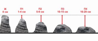
The indicator is standard, denoted by the letter “P” and the letter 1,...5. The higher the flow coefficient, the more water in the batch. For monolithic filling, mixtures P1, P2, P3 are used. They are prepared locally, the concrete is hard and sets quickly. Only P4 and P5 are delivered in a concrete truck.
The determination of “P” is carried out with a container in the form of a truncated cone with a volume of 6 liters and a height of 30 cm. It is determined how many cm the concrete has dropped after the cone has been removed from it.
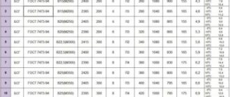
Cone shrinkage flow table
| Indicator "Mobility" | Sample shrinkage, mm |
| P1 - sedentary | 10-50 |
| P2 - sedentary | 50-100 |
| P3 – general purpose concrete | 100-150 |
| P4 - highly mobile | 150-200 |
| P5 - highly mobile | >200 |
There are three types of concrete compaction:
- vibration;
- compaction;
- bayoneting.
Vibrating with an electric vibrator most efficiently compacts even huge masses and is used for plate-type concrete. Tamping is used for heavy concrete using machine or hand tamping devices. In this case, compaction is carried out gradually and in layers, and the thickness of the treated mass should not exceed 15 cm.
The manual bayonet method uses a piece of pipe or fittings weighing from 2 to 4 kg. The rounded end of the iron rod is lowered into the concrete mass and pierces the concrete with jolting movements, every 10 cm2. Baying is carried out clearly in a spiral from the edges of the formwork to the middle of the structure.
Reinforcement configuration for NZLF, tape and slab
Strip foundations lying above the freezing depth are reinforced with a rectangular frame. An unlimited number of reinforcement lines can be located between the external ribs, between which the standard clearance must be maintained. As a rule, such frames consist of separately connected modules, the length of which is convenient for transportation and installation. Structural reinforcement here is represented by U-shaped or closed clamps encircling the working reinforcement bars every 0.6–1.1 meters.
Reinforcement of the straight section of the strip foundation: 1 - working longitudinal reinforcement; 2 - structural reinforcement (clamps).
Recessed foundations are strengthened like a strip - with a frame. The reinforcement lines, as mentioned, are duplicated and concentrated at the top and bottom edges. Additionally, intermediate lines can be laid to compensate for pressure forces and soil heaving, if required by the project. The reinforcement is connected to each other by vertical rods. This reinforcement looks structural, but it also performs a working function, significantly preventing torsional and lateral pressure deformations.
The slab is reinforced in the most simple way: two reinforcing mesh, each can consist of several layers. The meshes are spread to the upper and lower planes in accordance with the standard protective layer. The parameters of the reinforcing mesh are tabular; the rod and cell are calculated depending on the dimensions of the slab. As for the stiffening ribs under the slab, they are formed like the MZLF frames, and then fastened to the slab mesh with vertical rods of structural reinforcement.
Sealing seams
If there are wet processes in the room, the tightness of the seams becomes especially important, since the lack of tightness leads to peeling of organic coatings from the floor slab. This process is especially active at elevated temperatures in the premises.
During work, the number and location of seams are determined based not only on the coefficient of thermal expansion of the materials, but also taking into account the shrinkage of concrete and possible deformations that most often occur in areas where the floor interfaces with foundations for equipment, walls and columns.
SNiP requirements
Preparing and carrying out work on a concrete floor, determining the required number of seams and their length - all this is stipulated in the regulatory documentation for construction work. A preliminary work flow chart is issued, which takes into account all of the above points:
- purpose of the structure and premises, in particular;
- the thickness of the underlying layer, screeds and what brand of concrete will be used.
Ideally, when calculating and designing a structure, engineers try to place all the seams along the axes of the building so that they coincide with the expansion joints on the screed or the joints of reinforced concrete slabs.
The seams should:
- be mutually perpendicular to each other;
- the depth and thickness of the seams are made strictly in accordance with the project;
- the seams must be cut clearly within a certain time period of hardening;
- It is necessary to observe the width of the groove and the distance between them;
- When sealing joints, it is necessary to use pre-specified insulating mixtures.