Beton-House.com
Website about concrete: construction, characteristics, design. We combine the experience of professionals and private craftsmen in one place
Elements of round wells with and without bottom
The construction of external sewer networks is not complete without the installation of wells, since it is in them that the shaped and shut-off valves are concentrated.
Their walls can be built of brick, poured in a monolithic manner, but still, prefabricated reinforced concrete sewer wells are the most commonly designed option, which saves time and money. This is what we will talk about later, using the video in this article.
- For manholes
- Stages of work performed Preparation
SECTION III. ORGANIZATION AND TECHNOLOGY OF THE CONSTRUCTION PROCESS
1. Before starting work on constructing wells, the following must be done:
— make a breakdown of well construction sites;
— clear the area of forest, bushes, etc.
— demolish or move buildings and structures from the construction site;
— build temporary roads or exits from permanent roads to service construction.
2. Transportation of reinforced concrete well elements and other building materials (mortar, cement, reinforcement) to well construction sites is carried out by trucks with trailers from the supply bases of construction and installation organizations.
3. The construction of wells is carried out in the following sequence;
— development of a pit;
— cleaning the bottom of the pit, checking that the bottom marks and the steepness of the slopes comply with the design;
— treatment of the base for wells with tar or bitumen materials to a depth of at least 0.2 m with careful compaction;
— concrete preparation device;
— installation of a concrete tray, reinforced with horizontal reinforcing mesh, and sealing of the ends of the incoming and outgoing pipes;
— insulation of the inner surface of reinforced concrete rings with bitumen mastic;
— installation of prefabricated reinforced concrete well elements;
— grouting the seams between the well elements with cement mortar;
- cement plaster and iron tray;
— backfilling the well with soil with careful compaction and installation of a waterproof lock on the pipe entries;
— installation of a concrete blind area around the neck of the well 1.5 m wide;
— insulation of the joints of the reinforced concrete rings of the well with hot bitumen over a primer;
— well testing (after completion of construction of the sewer network section).
Due to the fact that pits for wells are being developed simultaneously with trenches, issues of excavation work are not considered in this technological map. In calculating the costs of constructing wells, only the amount of excavation work that is associated with widening the trenches in the places where the wells are installed is taken into account.
CONSTRUCTION OF WELLS
1. Preparation of the foundations for wells is carried out as earthworks are completed at the site.
2. A preparation of 100 mm thick M-50 concrete is laid on the base.
3. The reinforcement mesh of the tray base is laid on the concrete preparation, the incoming and outgoing pipelines are installed in the design position and a tray made of M-100 concrete is installed.
4. After the concrete tray has acquired the required strength, the prefabricated reinforced concrete elements of the well are installed using a truck crane.
5. For slinging the elements, a four-leg sling with a lifting capacity of 2.0 tons is used.
6. All elements of the well are installed on M-50 cement mortar.
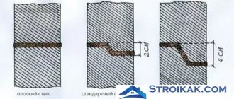
7. The construction of a clay castle is carried out after sealing the pipelines in the walls of the well. The width of the clay castle is taken to be 300 mm, and the height is 600 mm greater than the outer diameter of the pipelines connected to the well.
Well test
Wells of free-flow pipelines with internal waterproofing are tested for density by determining water leakage.
Testing of wells can be carried out either together with pipelines or separately. Before filling wells and trenches with soil, a preliminary test is carried out, and after filling, a final test is carried out.
Wells are tested for density no earlier than 24 hours after they are filled with water. Hydraulic pressure in a well in a leak test is created by filling the well to the top with water.
Wells are considered to have passed the preliminary test if no visible water leaks are detected during inspection. The amount of leakage should be determined by the volume of water added to the well to the original level during the test time, which should last at least 30 minutes. In this case, a decrease in the water level in the well is allowed no more than 20 cm. The well is recognized as having passed the final density test if the leakage or inflow determined during the test is equal to 60 l/day or less than this value.
Backfilling of trenches and pits
After testing the wells and pipelines, the well pits and trenches are backfilled layer by layer with soil using a bulldozer. Soil compaction is carried out using pneumatic rammers.
Preparatory stage of arrangement of reinforced concrete concrete structures
We carry out the following work:
- We determine the location where the well will be installed. There are several methods: using frames, based on geodetic surveys and electrical-vertical sounding. It is best to use all methods together.
On a note! The optimal time for constructing a well is August-September. They are also dug in winter, after 3 weeks of frost, when the upper layers of the soil freeze and they do not recharge the aquifer.
- We clear the area from bushes, trees, garbage and old buildings.
- We select the type and size of reinforced concrete rings (RCR), and also calculate their number.
- If necessary, we arrange temporary access roads for lifting equipment that delivers the necessary materials, as well as digging a pit (if you decide to drill a mine using a mechanized method).
Important! We do not recommend turning (that is, rolling) reinforced concrete rings over long distances. This is fraught with the fact that chips and cracks may form on the surface of the product.
SECTION IV. AND METHODS OF LABOR WORKERS
Work prior to the construction of sewer wells is carried out by four specialized units: concrete workers, pipe layers, insulators and bulldozer operators.
The composition of units by profession and the work they perform are shown in the table.
| No. of links | Team composition by profession | Qty | List of works |
| 1 | Concrete worker - 4 rubles. Concrete worker - 2 rubles. | 1 1 | Installation of concrete preparation and trays Plastering of trays Installation of concrete blind area. |
| 2 | Pipelayers 4 r. | 2 | Completion of the pit manually. Checking the elevation of the pit bottom and the steepness of the slopes. Construction of foundations for wells. Installation of well and neck elements with sealing of seams and grouting of the surface with cement mortar. Well test. Soil compaction when filling a well. |
| Pipelayers 3 r. | 2 | ||
| Pipelayers 1 r. | 1 | ||
| Truck crane operator 5 r. | 1 | ||
| 3 | Insulator 3 r. | 1 | Heating bitumen in a mobile boiler. Cleaning and painting the inner surface of the rings with bitumen. |
| Insulator 2 r. | 1 | ||
| 4 | Bulldozer driver 5 r. | 1 | Backfilling the well pit with soil. |
| TOTAL: | 11 people |
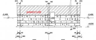
The placement of equipment, devices and tools in the work area during the installation of wells is shown in the work flow diagram.
SEQUENCE OF WORK EXECUTION
| No. pp. | Process name | Sequence of work operations |
| 1. | Well construction. | Cleaning slopes and pit bottom. Mixing the soil at the base of the well with bitumen or tar materials. Soil compaction. Concrete preparation device for a well made of M-50 concrete. Installation of reinforcing mesh. Construction of a concrete tray M-100. Insulation on the edge of the pit with hot bitumen of the inner surface of the rings. Installation of well and neck elements. Grouting of joints with ironing and coating with hot bitumen. |
| 2. | Well test | Preliminary test of the well with water (before backfilling the pit). Elimination of defects. Final testing of wells (after backfilling the pit). |
| 3. | Backfilling of pits and trenches. | Filling well pits with soil (after testing the wells). Compacting soil with pneumatic rammers. Construction of a concrete blind area around the well neck. |
Classification of wells
They are divided into two types:
- Sewer. They are necessary for the drainage of storm and wastewater.
- Water collection. Their name “speaks for itself.”
The difference between these two types lies in their operational characteristics, sizes and methods of arrangement. In turn, water-collecting reinforced reinforced concrete structures can be:
- Mine.
- Made in the form of a well.
And sewer wells can be:
- Or a septic tank with one or more chambers.
- Or a drain hole.
In our article we will dwell in detail on the arrangement of a water well.
METHODS AND TECHNIQUES OF WORK
The installation of concrete preparation and trays is carried out by unit No. 1 of the following composition:
concrete worker 4 r. — 1 person (1) link;
concrete worker 2 r. — 1 person (2).
The concrete mixture delivered to the well installation site is supplied by the concrete worker (2) to the laying site along a wooden tray. A concrete worker (1) located in the pit places concrete at the base of the well and compacts it using a hand tamper.
After the concrete preparation is installed, a reinforcing mesh is laid on it and the tray is concreted. Cleaning the bottom and slopes of the pit, preparing the base for the well, sealing the pipes in the tray and installing the well elements is carried out by unit No. 2 of the following composition:
truck crane operator 5 r. — 1 person (1)
pipe layer 4 r. — 1 person (2) link
pipe layer 4 r. — 1 person (3)
pipe layer 3 r. — 2 people (4;5)
pipe layer 2 r. — 1 person (6).
Before starting work on constructing a well, the pipelayer (4) cleans the slopes and bottom of the pit, checks compliance with the design of the bottom elevation and the steepness of the slopes of the pit.
Pipelayers (6 and 5) are busy working to saturate the soil at the base of the well with bitumen. The loosened and bitumen-impregnated soil is leveled and compacted using hand tampers.
Pipelayers (2 and 3) are busy preparing for the installation of reinforced concrete rings of the well, sealing pipelines into the tray, installing the well rings and installing a clay castle at the junction of the pipelines with the tray.
Arrangement of workers during the installation of wells: the pipe layer (5) is at the top and is engaged in slinging loads, the pipe layers (2 and 3) are installing the well elements in the pit, the pipe layer (4) is preparing the bases of the wells for installation and grouting the seams of the mounted well elements, and the pipe layer (6) - for auxiliary work (cleaning the reinforced concrete rings of the well from contamination, carrying materials, tools, etc.).
The pipe layer (5), having secured the lower ring of the well with a four-legged sling, gives a signal to the crane operator to lift the load. After a test lift to a height of 0.1-0.2 m above ground level, the pipe layer (5) checks the reliability of the sling and allows the ring to be delivered to its installation site. Pipelayers (2 and 3), having accepted the reinforced concrete ring of the well, install it on the tray with mortar. After verifying that the ring is installed correctly, it is unslinged and a signal is given to the link members to remove the slings and prepare for the installation of the next ring.
The cement mortar protruding from under the rings (during their installation) is removed, and the seam is thoroughly rubbed inside and outside the well. The correct installation of the rings is checked by level and plumb. The final well installation operations are the installation of the hatch (cage and cover) with the sealing of the cage on the neck with M-50 cement mortar and the installation of a clay castle.
Insulation of reinforced concrete well rings with bitumen is carried out by unit No. 3, consisting of two insulators of the third (1) and second (2) categories.
The insulator (2) heats the bitumen in a mobile boiler, and the insulator (1) prepares the reinforced concrete rings for insulation (cleaning off contaminants, applying a primer, etc.).
After the primer has dried, insulators (1 and 2) use brushes to apply hot bitumen to the inner surface of the rings at a distance of 5 cm from the edges.
After installing the well rings and sealing the joints, insulators (1 and 2) prime the joints and apply bitumen to them.
Hydraulic testing of the well is carried out by link No. 2 by filling it with water and observing its leakage. A preliminary test is carried out before filling the well with soil and is aimed at identifying visible water leaks, and the final test is to determine the amount of leakage, which should not exceed 60 l/day for a given well.
The well is filled with soil in layers using a bulldozer. Each layer is compacted by a pipe layer (4) using a pneumatic rammer.
The completion of the well construction is the installation of a concrete blind area around the neck. The concrete blind area is arranged by the concrete workers of unit No. 1 in the following order: the concrete worker (2) scatters crushed stone around the neck and then compacts it, and the concrete worker (1) lays concrete on the prepared base and levels it.
Schedule for the construction of prefabricated reinforced concrete wells with a diameter of 1.0 m and a depth of 3.0 m on sewer networks
Note. The labor costs of the truck crane operator are not taken into account in the schedule.
SAFETY
Work in excavations with slopes that have been moistened after soil removal is permitted provided that precautions are taken against soil collapse, namely:
a) a thorough inspection by the workman or foreman before the start of each change in the condition of the soil and its artificial collapse in places where “peaks” and cracks are found at the edges and on the slopes;
b) temporary cessation of work in the excavation until the soil is drained if there is a danger of a collapse;
c) local reduction of the steepness of the slope in areas where work in the excavation is urgent;
d) prohibition of the movement of vehicles and mechanisms within the collapse prism.
When installing a well, a person from among the engineering and technical personnel must be appointed, responsible for the safe execution of work on moving and installing loads with cranes.
All lifting mechanisms and devices (crane, slings) must be periodically checked before starting operation, as well as during operation, in accordance with the rules of Gosgortekhnadzor.
When installing well elements, the edges must work on outriggers. The lifting capacity of the slings must correspond to the weight of the load being lifted. Lifting and moving well elements should only be done after checking the correctness and reliability of their slinging. When lifting, moving and lowering the well elements with a crane, it is prohibited for people to remain in the area of its operation; the well elements must not be allowed to be moved above the pipelayers’ workplace. The supplied well element should be lowered above the place of its installation by no more than 30 cm, and only from this position the pipelayers direct it to the design position.
Workers who are at least 18 years old, who have passed a medical examination and trained according to a special program approved by Gosgortekhnadzor and certified by the qualification commission with the issuance of certificates, are allowed to work as a sling operator.
Unslinging the installed well elements is allowed only after they have been firmly and securely fastened. It is prohibited to swing a suspended load and leave it hanging without supervision, as well as to carry out installation in a wind force of more than 6 points.
The operation of a jib crane near power lines is permitted only if the horizontal distance between the extreme point of the mechanism, cargo ropes (cables) or load (at the greatest reach of the working body) and the nearest power line wire is not less than that specified in Table 1.
Permissible horizontal distance from operating machines to power cables
Table 1.
| Transmission line voltage in kV. | up to 1 | 1-20 | 35-110 | 154 | 220 | 330-500 |
| Distance in m | 1,5 | 2 | 4 | 5 | 6 | 9 |
When moving a jib crane, as well as when transporting well elements under the wires of existing power lines, the vertical distance between the highest point of the machine and load being moved and the lowest point of sagging of the wire must be no less than that specified in Table 2.
Permissible vertical distance from the equipment being moved to power cables
Table 2.
| Transmission line voltage in kV. | up to 1 | 1-20 | 35-110 | 154-200 | 330 | 500 |
| Distance in m | 1 | 2 | 3 | 4 | 5 | 6 |
Subject to the above breaks, work can be carried out if there is written permission from the electricity supply organization to carry out work in the security zone and if the crane operator has a work permit signed by the chief engineer of the SUM. This work must be carried out under the direct supervision of an engineer and technical worker appointed by order and having permission from the State Mining and Technical Supervision Authority.
Loading of rigging equipment exceeding that for which this equipment is approved for operation is not allowed.
Loads must be slinged according to pre-developed schemes.
Lifting loads covered with earth, snow or frozen to the ground is not allowed. It is prohibited to pull (drag) loads with lifting mechanisms by slanting ropes or turning the boom.
It is strictly forbidden to leave lifted loads suspended. Removing hooks from lowered structures is permitted only after installing them in the design position. Moving structures after their installation and removal of gripping devices is prohibited.
The mortar under the installed structures must be laid before the structure is delivered to the place of its installation.
Heating bitumen within wells, trenches and other cramped places is prohibited. Due to the fact that hot bitumen can cause burns if it comes into contact with the human body, even if covered with ordinary cotton fabric, workers must be provided with the following protective clothing and footwear:
a) canvas jackets and trousers (trousers must be wide and worn over the shoulder);
b) leather shoes or boots;
c) canvas mittens:
d) glasses with simple lenses to protect the eyes from accidental splashes of hot mastic.
Overalls must always be in perfect working order. Work without a full set of overalls and shoes is not permitted.
1. Basic materials and products.
| No. pp. | Name of materials | GOST brand | Unit change | Quantity |
| 1. | Support ring | KO GOST 8020-56 | PC. | 1 |
| 2. | Adjustment stones | KR GOST 8020-56 | PC. | 6 |
| 3. | Neck rings | K-7-3 GOST 8020-56 | PC. | 2 |
| 4. | Floor slab | P-10 GOST 8020-56 | PC. | 1 |
| 5. | Rings | K-10-9 GOST 8020-56 | PC. | 2 |
| 6. | Luke | TU-264-55 | PC. | 1 |
| 7. | Cement mortar | M-50 | m3 | 0,06 |
| 8. | Concrete | M-50 | m3 | 0,33 |
| 9. | Concrete | M-100 | m3 | 0,55 |
| 10. | Bitumen | — | kg | 49 |
| 11. | Petrol | — | kg | 3,2 |
| 12. | Reinforcing mesh | PC. | 1 | |
| 13. | Crushed stone | m3 | 0,22 |
Machinery, equipment and power tools.
| No. pp. | Name | Type | Brand | Quantity |
| 1 | Automotive crane | LAZ-690 | 1 | |
| 2 | Bulldozer | D-159.B | 1 | |
| 3 | Compressor | PKS-5 | 1 | |
| 4 | Pneumatic rammers | I-157 | 1 |
Inventory and devices.
| № | Name | Unit change | Quantity |
| 1 | 2 | 3 | 4 |
| 1. | Cross saws | PC. | 1 |
| 2. | Bayonet shovels | PC. | 4 |
| 3. | Steel crowbars | PC. | 2 |
| 4. | Picking shovels | PC. | 3 |
| 5. | Bench hammers | PC. | 2 |
| 6. | Tape measures 10 m | PC. | 1 |
| 7. | Folding meter | PC. | 2 |
| 8. | Metal level | PC. | 2 |
| 9. | Metal plumb line | PC. | 1 |
| 10. | Bench chisels | PC. | 5 |
| 11. | Axes | PC. | 2 |
| 12. | Adjustable wrenches | PC. | 2 |
| 13. | Opening fork | PC. | 1 |
| 14. | Mobile container for cement | PC. | 1 |
| 15. | Universal sling with a lifting capacity of 2.0 tons. | PC. | 2 |
| 16. | Four-legged sling with a lifting capacity of 4 tons. | PC. | 2 |
| 17. | Mobile boiler for heating bitumen | PC. | 1 |
| 18. | Inventory plugs for hydraulic testing | PC. | 6 |
| 19. | Stairs | PC. | 3 |
| 20. | Transitional bridges | PC. | 2 |
| 21. | Level | PC. | 1 |
| 22. | Leveling slats | PC. | 2 |
| 23. | Template for tray arrangement | PC. | 1 |
| 24. | Wooden tray 3.5 m long. | PC. | 1 |
| 25. | Mason's Trowels | PC. | 2 |
| 26. | Plastering trowels | PC. | 2 |
| 27. | Buckets | PC. | 4 |
| 28. | Mortar box | PC. | 2 |
| 29. | Brushes | PC. | 5 |
| 30. | Manual tamping | PC. | 1 |
Distance from septic tank
The distance from the house to the septic tank according to the standards and unambiguous requirements of sanitation is a necessary parameter developed in the era of state standardization and ongoing scientific research on sanitation and hygiene. Sanitary standards and regulations do not allow making a septic tank closer than the prescribed minimum distance.
At the summer cottage
Violation of them is fraught not only with a fine from the sanitary inspection that monitors compliance with SanPiN, but also with liability under a special article of the Code of Administrative Offences.
However, in this case, the desire to remove it at a considerable distance from the residential building brings inconvenience to the residents. The erroneous principle “the further the better” in this case makes a person feel uncomfortable in case of an emergency or bad weather outside
The rules for installing a septic tank are not among the easily resolved problems, since this issue is given priority attention
In the countryside
SanPiN considers the norm for removing a structure as a variable figure; in some sources it ranges from 5 to 10 m. The upper permissible distance is provided for simple devices without a bottom or homemade ones, which may have flaws in design and construction.
It is possible to install a septic tank at a minimum distance, provided that the system operates using modern technologies and complies with the standards for a specific type of building - SNT or individual housing construction.
The difference in requirements, according to the new law of 2022, for a garden plot is its almost always minimum dimensions, while on residential plots there may be ranges that allow you to safely choose a location even according to the stated standards. From the moment the law comes into force, treatment facilities and their location on the site will depend not only on the status of the building, country house (and now garden) or residential.
In stock
It is necessary to take into account
The fundamental difference lies in the requirements for the capacity of the septic tank and its arrangement system. Because according to the requirements of SanPiN 2.2.1/2.1.1.1200-03, permanent or seasonal residence, the number of people living in the house and the approximate amount of waste produced per day should be taken into account. It is known to depend on the number of residents and their temporary or permanent residence.
Standard distances from the septic tank according to SNiP and SanPiN
Failure to observe even the minimum distance from the septic tank is fraught with various consequences:
- According to existing rules, an outdated or incorrectly located structure should be located no closer than 5 meters from the house, because leakage can lead to destruction of the foundation.
- The distance from the external sewer depends on the type and diameter of the pipes used - otherwise they may be gradually destroyed by caustic excrement and rotting sewage.
- The optimal distance of 4 meters from the trees to the septic tank is associated with possible risks due to the growth of a powerful root system, which large trees are prone to. For the same reasons, a similar distance from them to the house and well is maintained.
- The distance standards from a residential building can be significantly reduced if the developer has the opportunity to install a safe Topas septic tank. You can also purchase another version of the system that does not require cleaning with a sewer machine, otherwise the odors and insects attracted by them will be in close proximity to the house.
Minimum distance from the septic tank on a summer cottage according to SNiP and SanPiN standards
The installation of a septic tank at the proper distance is regulated not only by sanitary standards. In 1999, Law of the Russian Federation No. 52-FZ “On the sanitary and epidemiological welfare of the population” was adopted.
The Code of Administrative Offenses has a special article providing for administrative and financial liability for creating an epidemiological threat and violating environmental safety standards.
But the decision on the illegality of installing a septic tank is made based on a set of requirements - the type of soil, the type of device, its manufacturability and the cleaning method used. Each option is considered separately.
Layout of buildings on individual housing construction and SNT sites in accordance with SNiP standards
Installation of reinforced concrete rings for a storage well
To build a sewer well with your own hands, first of all, you need to “plant” the first ring of the shaft on an M100 grade solution. This is followed by:
- Make holes for sewer pipes. They must fit into the shaft ring at least 100-150 mm;
- The gaps between the pipes and the wall of the reinforced concrete ring should be sealed with cement mortar;
- Now at the bottom of the well you need to make a concrete trench, the diameter of which would correspond to the internal diameter of the sewer pipe;
- Then a second one is installed on the first casing ring so that their locking connections are located at the same level;
- The subsequent casing rings are installed in a similar manner;
- At the final stage, a lid with a hatch is installed to protect the tank from the accumulation of precipitation.
SECTION V. MATERIAL AND TECHNICAL RESOURCES
1. Basic materials and products.
| No. pp. | Name of materials | GOST brand | Unit change | Quantity |
| 1. | Support ring | KO GOST 8020-56 | PC. | 1 |
| 2. | Adjustment stones | KR GOST 8020-56 | PC. | 6 |
| 3. | Neck rings | K-7-3 GOST 8020-56 | PC. | 2 |
| 4. | Floor slab | P-10 GOST 8020-56 | PC. | 1 |
| 5. | Rings | K-10-9 GOST 8020-56 | PC. | 2 |
| 6. | Luke | TU-264-55 | PC. | 1 |
| 7. | Cement mortar | M-50 | m3 | 0,06 |
| 8. | Concrete | M-50 | m3 | 0,33 |
| 9. | Concrete | M-100 | m3 | 0,55 |
| 10. | Bitumen | — | kg | 49 |
| 11. | Petrol | — | kg | 3,2 |
| 12. | Reinforcing mesh | PC. | 1 | |
| 13. | Crushed stone | m3 | 0,22 |
Machinery, equipment and power tools.
| No. pp. | Name | Type | Brand | Quantity |
| 1 | Automotive crane | LAZ-690 | 1 | |
| 2 | Bulldozer | D-159.B | 1 | |
| 3 | Compressor | PKS-5 | 1 | |
| 4 | Pneumatic rammers | I-157 | 1 |
Inventory and devices.
| № | Name | Unit change | Quantity |
| 1 | 2 | 3 | 4 |
| 1. | Cross saws | PC. | 1 |
| 2. | Bayonet shovels | PC. | 4 |
| 3. | Steel crowbars | PC. | 2 |
| 4. | Picking shovels | PC. | 3 |
| 5. | Bench hammers | PC. | 2 |
| 6. | Tape measures 10 m | PC. | 1 |
| 7. | Folding meter | PC. | 2 |
| 8. | Metal level | PC. | 2 |
| 9. | Metal plumb line | PC. | 1 |
| 10. | Bench chisels | PC. | 5 |
| 11. | Axes | PC. | 2 |
| 12. | Adjustable wrenches | PC. | 2 |
| 13. | Opening fork | PC. | 1 |
| 14. | Mobile container for cement | PC. | 1 |
| 15. | Universal sling with a lifting capacity of 2.0 tons. | PC. | 2 |
| 16. | Four-legged sling with a lifting capacity of 4 tons. | PC. | 2 |
| 17. | Mobile boiler for heating bitumen | PC. | 1 |
| 18. | Inventory plugs for hydraulic testing | PC. | 6 |
| 19. | Stairs | PC. | 3 |
| 20. | Transitional bridges | PC. | 2 |
| 21. | Level | PC. | 1 |
| 22. | Leveling slats | PC. | 2 |
| 23. | Template for tray arrangement | PC. | 1 |
| 24. | Wooden tray 3.5 m long. | PC. | 1 |
| 25. | Mason's Trowels | PC. | 2 |
| 26. | Plastering trowels | PC. | 2 |
| 27. | Buckets | PC. | 4 |
| 28. | Mortar box | PC. | 2 |
| 29. | Brushes | PC. | 5 |
| 30. | Manual tamping | PC. | 1 |