STATE STANDARD OF THE USSR UNION
CONCRETE AND REINFORCED CONCRETE STRUCTURES FOR WELLS OF SEWER, WATER AND GAS NETWORKS
TECHNICAL CONDITIONS
GOST 8020-90
STATE CONSTRUCTION COMMITTEE OF THE USSR
Moscow
STATE STANDARD OF THE USSR UNION
| CONCRETE AND REINFORCED CONCRETE STRUCTURES FOR WELLS OF SEWER, WATER AND GAS NETWORKS Specifications Concrete and reinforced structures for holes in sewage, water and gas supply pipelines. Specifications | GOST 8020-90 |
Date of introduction 07/01/90
This standard applies to concrete and reinforced concrete structures made from heavy concrete and intended for the construction of round wells for underground pipelines of sewer, water and gas networks.
The structures are used in accordance with the instructions of the working drawings of a particular pipeline.
INFORMATION DATA
1. DEVELOPED AND INTRODUCED by the All-Union Design and Research Association for Water Supply and Sewerage (Soyuzvodokanalniiproekt) of the USSR State Construction Committee and the Main Department of Architecture and Urban Planning of Moscow
DEVELOPERS
L.N. Borovik; G.N.Afonin (topic leaders); L.V. Yaroslavsky; Yu.P. Almazov; G.I. Bryantseva; N.K. Kozeeva; L.P. Shchepin; A.N.Kondaurov; V.E. Sheiko; M.L. Zaichenko, Candidate of Technical Sciences; R.M.Koltovskaya; V.I. Pimenova; V.I. Denshchikov
2. APPROVED AND ENTERED INTO EFFECT by Resolution of the State Construction Committee of the USSR dated January 15, 1990 No. 1
3. INSTEAD GOST 8020-80
4. REFERENCE REGULATIVE AND TECHNICAL DOCUMENTS
| Designation of the referenced technical document | Number of paragraph, subparagraph | Designation of the referenced technical document | Number of paragraph, subparagraph |
| GOST 5781-82 | 1.3.5; 1.3.8 | GOST 13015.3-81 | 2.3 |
| GOST 6727-80 | 1.3.5 | GOST 13015.4-84 | 4.1 |
| GOST 10060-87 | 3.2 | GOST 17624-87 | 3.1 |
| GOST 10180-78 | 3.1 | GOST 17625-83 | 3.6 |
| GOST 10884-81 | 1.3.5 | GOST 18105-86 | 3.1 |
| GOST 10922-75 | 1.3.7; 3.5 | GOST 22690-88 | 3.1 |
| GOST 12730.0-78 | 3.3; 3.4 | GOST 22904-78 | 3.6 |
| GOST 12730.3-78 | 3.4 | GOST 23009-78 | 1.2.5 |
| GOST 12730.5-84 | 3.3 | GOST 23858-79 | 3.5 |
| GOST 13015.0-83 | 1.3.1; 1.3.3; 1.3.11 | GOST 26433.0-85 | 3.7 |
| GOST 13015.1-81 | 2.1 | GOST 26433.1-89 | 3.7 |
| GOST 13015.2-81 | 1.5.1 | GOST 26633-85 | 1.3.2 |
5. An amendment was made, published in the IUS No. 3 of 1991.
The amendment was made by the Codex legal bureau.
This standard applies to concrete and reinforced concrete structures made from heavy concrete and intended for the construction of round wells for underground pipelines of sewer, water and gas networks.
The structures are used in accordance with the instructions of the working drawings of a particular pipeline.
How to calculate the volume of reinforced concrete rings
In order to determine the volume of sewer well rings, you should use a special table of the ratio of sizes and volume indicators.
Here you can see such indicators as the internal diameter of the product, its wall thickness, and volume.
Accordingly, in order to determine which reinforced concrete rings are needed for sewerage, you first need to calculate the total volume of the well.
Table of reinforced concrete rings
Calculations will be carried out using a very simple formula.
Here you need to multiply three indicators:
- the number of people permanently living in the house. Let's take 5 for example;
- daily water requirement per person in liters. Today this figure is 200 liters;
- the number of days during which the wastewater is completely processed. This is 3 days.
Reinforced concrete rings for 3 cubic meters together
Thus, by making a simple calculation: 5*200*3, we get 3000 liters.
Converting this figure into cubic meters, we get 3m 3.
This is exactly the volume that a sewer well should have for a family of 5 people.
Calculation of internal volume
The internal volume of the ring is calculated using a simple formula. Here you need to multiply R 2 - the radius by the height of the product and by 3.14 - a constant value.
Accordingly, to obtain the radius of the ring, we need to perform the calculation in reverse order.
We divide the total volume by 3.14 and the height of the well, which in our case is 2.3 meters with a total depth of 2.5 meters.
This gives the formula: R 2 =3/2.3/3.14. As a result, the radius will be 0.65 m.
It turns out that the diameter of the sewer well should be 1.3 m. Such products are not produced, so we take rings with a diameter of 1.5 m.
ACCEPTANCE
2.1. Acceptance of structures is in accordance with GOST 13015.1 and this standard. In this case, designs are accepted based on the results:
periodic testing - in terms of frost resistance, water resistance and water absorption of concrete;
acceptance tests - in terms of concrete strength (class or grade of compressive strength and tempering strength), compliance of reinforcement and embedded products with working drawings, strength of welded joints, thickness of the protective layer of concrete to the reinforcement, accuracy of geometric parameters, quality of the concrete surface.
Acceptance of structures for strength, rigidity and crack resistance is carried out according to a set of standardized and design indicators in accordance with the requirements of GOST 13015.1.
2.2. Acceptance of structures in terms of accuracy of geometric parameters, thickness of the protective layer of concrete to reinforcement, and surface quality is carried out based on the results of random inspection.
2.3. The document on the quality of structures in accordance with GOST 13015.3 must additionally indicate concrete grades for frost resistance and water resistance of concrete (if these indicators are specified in the order for the manufacture of structures).
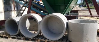
Reinforced concrete wells
Reinforced concrete prefabricated wells are special elements of buried structures that are used for the construction of various types of communications: sewer, water supply, gas networks and inspection wells. Depending on the area of operation, reinforced concrete rings of various diameters are used for the construction of prefabricated wells.
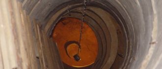
Reinforced concrete wells are a vertical hollow structure consisting of reinforced wall rings, a bottom and a cover on which a hatch is installed. As a rule, wells are almost or completely immersed in the ground and are located above or below the groundwater level in non-aggressive and slightly aggressive environments.
According to their purpose, reinforced concrete wells are divided into several types:
- Tap water. They are elements of the water supply network, heat and water supply and are intended for installing valves (so-called shut-off valves) to regulate the flow of various liquids, fire hydrants, measuring equipment, etc.;
- Sewage (drainage, treatment). Designed to create sewer systems at bends, in places where pipes drop, etc. They are used to combat groundwater that destroys the foundation;
- Gas pipelines. Serve as elements of main gas pipelines.
Based on functionality, wells are divided into several types:
- Observation rooms - used to monitor the operation of the entire system;
- Drop pipes are necessary in places where there are strong differences in pipes, when the network is turned or when the network level changes due to the characteristics of the landscape. They are used when combining pipelines of various depths into one network;
- Rotary. These wells are used in places where pipes turn to avoid blockages. Also often used as viewing rooms;
- Filtration (filtration) wells are necessary for wastewater treatment. Installed above the groundwater level;
- Cumulative. They are used to accumulate wastewater and are usually installed at the lowest point of the site to ensure the optimal angle of inclination of the sewer pipeline.
Advantages of using reinforced concrete as a material for the production of wells:
- Durability of products. Reinforced concrete allows wells to withstand the load that occurs due to soil pressure, and its dense structure is not subject to erosion by groundwater;
- Concrete wells are suitable for most soils;
- The smooth surface of concrete wells does not allow debris to cling to the walls and form blockages. In addition, concrete is easily cleaned, and cleaning does not require special equipment or qualified specialists;
- Unlimited service life. Concrete products are famous for their durability even when used in aggressive environments and places where there is a fairly high level of humidity;
- Simplicity and ease of installation and repair. The elements of a prefabricated well are easily mounted on top of each other. Thanks to this, repairs do not require a complete replacement of the structure - it is enough to just replace or repair the worn element;
- Concrete is inert - it does not have any effect on water quality.
Assembled reinforced concrete wells consist of several elements: wall rings, bottoms, covers and hatches. Road construction involves the use in some cases of wells equipped with floor slabs. The presence of certain elements in the structure depends on the purpose of the prefabricated well. Technically, these elements are divided:
- Concrete rings. They are through thin-walled hollow cylindrical elements that serve directly for forming and laying the well;
- Well covers or, as they are also called, floor slabs. These slabs not only provide protection to the water from contamination, but also prevent the danger of a person falling inside the well. They have a special hole in their design for installing a hatch;
- Bottom plates (bottom). Monolithic reinforced concrete slabs that serve as the bottom and perform the function of waterproofing wells;
- Support rings. These are additional prefabricated elements that are intended for structures of non-standard height for road construction. They are identical in size to standard rings, but have a significantly smaller height;
- Support plates. They have a rectangular shape with a round or rectangular outlet in the middle, which is subsequently closed by a round iron hatch or a rectangular wastewater grate. The rectangularity of the base plate allows you to protect the well itself from destruction. Thanks to this shape, the load is directed evenly over the entire perimeter of the slab, and the walls of the well receive minimal load, which helps maintain the long-term functionality of the structure itself;
- Rings with caps. They are located at the top of the structure and ensure the safe operation of wells. The hole in the lid on which the cast-iron hatch is installed is necessary to provide free access to the inside of the well;
- Sewer wells are standardized cylindrical concrete structures that are designed to create underground sewerage, gas and water supply systems. Inside the sewer well there is a metal mesh 0.6 - 1 mm thick;
- The hatches are cast iron. They close the wells and prevent large foreign objects from entering the system, and also protect against accidents.
When choosing reinforced concrete wells, it is necessary to take into account the characteristics of the structure being built. For example, concrete rings for wells located on highways are always equipped with floor slabs and hatches, and if it is necessary to ensure watertightness of the structure, concrete rings with a bottom are used.
Prefabricated reinforced concrete wells are manufactured in accordance with the requirements of GOST 8020-90 and series 3.900.1-14. “Reinforced concrete products for round wells for water supply and sewerage”, issue 1 “Instructions for use and working drawings” made of heavy concrete with a compressive strength class of B15. The base plates of the wells are made of heavy B20 concrete. The frost resistance grade of concrete for the working chambers of wells is no less than F75, for other products - no less than F100. The waterproof grade must be at least W6.
Reinforcement of the working chambers of reinforced concrete wells is carried out with volumetric reinforcing cages made on special machines, similar to the type of frames used for reinforcing round reinforced concrete pipes. Road construction also allows for the production of frames by bending conventional reinforcement mesh. Reinforcement of the bottom of wells is done with meshes cut from three-dimensional frames at the holes, with the exception of water and gas wells, the bottom of which is reinforced with special reinforcing meshes. For the reinforcement of structures, types and classes of reinforcing steel are used: thermomechanically strengthened rod of classes At-IIIC and At-IVC according to GOST 10884; hot-rolled rod of classes A-I, A-II and A-III according to GOST 5781; reinforcing wire of class BP-I according to GOST 6727.
Prefabricated reinforced concrete wells and elements are marked with an alphanumeric designation, where:
- CL - working chamber of a sewer well;
- BC - working chamber of the drainage well;
- KFK - working chamber of a domestic sewage well;
- KDK, DK - working chamber of the well of intra-block networks;
- KLK - working chamber of a storm sewer well;
- KLV, VD - working chamber of the storm sewer water intake well;
- KVG - working chamber of a well for water and gas networks;
- KS - wall ring of the working chamber or well neck;
- KO - support ring;
- PO - base plate;
- PD - road slab;
- PN - bottom plate;
- PP - floor slab;
- PC - wall ring with covers;
The numbers after the letters indicate the diameter in decimeters of the working chamber, neck or hatch of the reinforced concrete well with which the element mates. The numbers after the dot in the mark of the wall rings indicate the height of the ring in decimeters. Lowercase letters after the numbers in the type of wall rings indicate the design of the rings with additional design features: a - with two holes for passing pipelines, b - with four. The numbers after the hyphen in the type of floor slabs indicate the type of load-bearing capacity of the slab.
Labeling of products in accordance with the album of unified products RK 2201-82 using an alphanumeric system, where:
- BC - working chambers of drainage wells,
- VD - working chambers of water intake (rainwater) wells,
- VG - working chambers of wells installed on water and gas networks,
- PC - a round slab for covering wells with a hole at the edge of the slab,
- PVG - a round slab for covering wells with a hole at the center of the slab,
- K - well neck rings.
The numbers at the end of the stamps show the internal diameter of the working chambers of the wells and necks in decimeters.
You can order elements of reinforced concrete wells, as well as consult with our specialists and select the required reinforced concrete structures. In our sales department you can find out in advance to clarify the price of wells and calculate the total cost of the order. You can buy wells and consult on general issues of purchase and delivery by calling the BLOK Group company: St. Petersburg , Moscow , Krasnodar: (861) 279-36-00 . Company operating hours: Mon-Fri from 9-00 to 18-00. The company GC BLOK delivers reinforced concrete wells throughout Russia directly to the customer’s site or to the construction site, if the infrastructure allows.
CONTROL METHODS
3.1. The strength of concrete structures is determined according to GOST 10180 on a series of samples made from a concrete mixture of the working composition and stored under the conditions established by GOST 18105.
When testing by non-destructive methods, the actual tempering compressive strength of concrete should be determined by the ultrasonic method in accordance with GOST 17624 or mechanical devices in accordance with GOST 22690, as well as other methods provided for in the standards for concrete testing methods.
3.2. The frost resistance of concrete is determined according to GOST 10060 on a series of samples made from a concrete mixture of the working composition.
3.3. The water resistance of concrete is determined according to GOST 12730.0 and GOST 12730.5.
3.4. Water absorption of concrete is determined according to GOST 12730.0 and GOST 12730.3.
3.5. Welded reinforcement and embedded products are controlled according to GOST 10922 and GOST 23858.
3.6. The dimensions and position of reinforcement and embedded products, as well as the thickness of the protective layer of concrete before the reinforcement are determined according to GOST 17625 or GOST 22904.
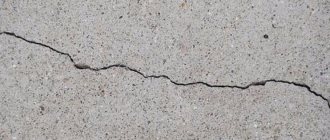
3.7. Dimensions, deviations from the flatness of structures, the width of the opening of surface technological cracks, the dimensions of cavities, sagging and edges of concrete structures are checked by the methods established by GOST 26433.0 and GOST 26433.1.
3.8. The dimensions of the structures are checked as follows:
the outer and inner diameters of the working chambers, wall and support rings, floor slabs and bottoms are measured along two mutually perpendicular diameters;
the thickness of the walls of the working chambers and wall rings is measured in four places along two mutually perpendicular diameters;
the height of the working chambers and wall rings is measured along four generatrices in two diametrically opposite sections;
the thickness of the slabs and support ring is measured in four places in two mutually perpendicular directions.
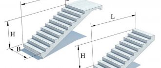
What are trays for?
The essence of the operation of drainage systems is the timely removal of precipitation and melt water accumulating on the road surface. For this purpose, the road surface is given a transverse and longitudinal slope, and storm drains are installed in the right places. Through these drainage pits, water enters a complex channel system consisting of drainage trays, stop blocks and other elements. The water diverted through these channels is discharged into acceptable locations, such as into the local river system.
If you neglect to organize high-quality drainage, sediment and melt water will accumulate on the road. And this is fraught with the destruction of road pavement and erosion of the roadbed, which in turn will lead to a rapid cessation of the functioning of the road.
TRANSPORTATION AND STORAGE
4.1. Transportation and storage of structures - in accordance with GOST 13015.4 and this standard.
4.2. The structures are transported and stored in working position.
4.3. Structures should be stored:
working chambers - in one row;
wall rings - in two rows in height in accordance with the diagram shown in Fig. 1;
Scheme for storing wall rings of wells
Crap. 1
support rings and plates - no more than six rows in height on spacers (linings) in accordance with the diagram shown in Fig. 2.
Scheme for storing floor slabs and well bottoms
1 — gaskets (linings); 2 — mounting loops.
Crap. 2
Other storage schemes are permitted, provided the safety of structures is ensured and safety requirements are met.
General information
Types of networks
A sewer network is a communication with different branches, which consists of different pipes and represents one whole.
This system is necessary for transporting wastewater from users to specialized containers in which water is processed and purified.
There are two types of sewer networks:
- Internal;
- Outdoor.
Pipes and treatment systems that are located on the street refer to the external type of sewer networks. And the pipes that are located inside houses are classified as internal.
In such communications, wastewater is transported both under pressure and by gravity.
Therefore, all sewerage pipelines are divided into:
- Non-pressure;
- Pressure.
Gravity pipelines of sewerage systems are installed at an angle to ensure the movement of wastewater to the final point. For the installation of free-flow sewerage, polyethylene pipes are used.
Pressure sewer networks operate according to this principle: the pump builds up pressure and, under its action, wastewater is discharged. For pressure pipelines, pipes of good strength are used, this is necessary so that they can cope with pressure.
Also, sewer systems, depending on the purpose, are divided into the following types:
- Storm sewers (discharging melt and rain water);
- Production;
- Economic and household.
- Storm drainage is needed to remove rain and melt water.
Household sewerage is divided into two types:
- Autonomous (local);
- Central (main).
The central type of sewer system removes sewage from houses in a city area or populated area, and an autonomous sewer system serves only one house (in isolated cases, several houses).
The method of installing external sewers is divided into:
- Separate;
- General alloy;
- Semi-separated.
External sewer networks
There are several types of sewer networks that are laid externally.
Trace. This design is installed from a point to a specialized tank. Tracing is also installed in an apartment building (observing all building rules and regulations). Pipes are laid only vertically. The distance from the outer wall of the building to the communications must be at least three meters. Trace installation is carried out only when there are connections to the central sewerage network.
External sewerage consists of pipes, wells and collectors.
Sewage network located on the street. This system consists of a complex system of wells and pipes. It is done on the streets of the city. Through street sewer networks, wastewater moves to the central sewerage system, and then to treatment systems.
Collectors. These devices are designed to collect sewage and redirect it if necessary. Sewage is redirected from collector to collector, which is located near the sewerage basin or on its territory. The work of the collector is to transport wastewater by gravity or under pressure.
Treatment buildings are the final destinations for sewage. These facilities concentrate and purify wastewater. After the water is purified, it is discharged into reservoirs and then used for economic purposes.
The laying of sewer networks takes place in different ways because it depends on specific cases.
Fittings for plastic pipes
PVC sewerage fittings
A fitting is the part of the pipeline needed to connect a pair of pipes at an angle, in the case of joining more than two pipes, etc.
The fittings also allow you to connect the local sewer system to the city main.
Where are fittings used? Most often they can be found during the installation of sewage systems in residential buildings, and these can be both residential buildings in the city and beyond, and in high-rise apartments. The fittings can be used in systems through which wastewater passes at a temperature of no more than 80° C, as well as for the removal of short-term wastewater at a temperature of 95° C. The drainage is intended not only for dirty water from a sink, toilet or shower stall, but also for certain chemical compositions, the coefficient of which, recognizable as pH, has a spectrum from 2 to 12.
Types of fittings
Fittings for external and internal sewerage
According to their type, fittings can be as follows:
- those that are used in systems installed inside the house;
- those used in systems outside the home.
The method of connecting fittings is also different and can be done using a rubber gasket in the form of a ring and, in rare cases, by gluing.
The O-ring is not used as a last resort.
Recommendations for selection
The shaped element for sewerage is selected according to the following criteria:
Material of manufacture. It is desirable that it completely matches the type of pipes used to lay the collector. Internal section of products. It must correspond to the diameter of the pipes: if the collector has a cross-section of 110 mm, the outlet for sewer pipes is taken with a diameter of 110 mm, no more and no less. Availability of rubber seals. They greatly facilitate the sewer installation process. Product compliance with GOST. As a rule, there is a corresponding marking on the outside of the product. Bend angle
It is important to correctly calculate the line configuration in order to avoid errors when arranging its direction. The presence of a flat, smooth inner surface of the product. Otherwise, in the future, wastewater with large inclusions will provoke the formation of growths on the walls of the collector.
Problems and difficulties in designing external and internal networks
The main difficulties in preparing sections of the project for utility networks are associated with the following points:
- with the restrictions specified in the technical specifications for connection;
- lack of technical capability to connect the facility to general networks, the need for serious additional costs for connecting communications;
- poor condition of current networks and equipment, they need to be replaced and restored;
- the need to strengthen building structures for the installation of internal or external networks.
To avoid difficulties during design and coordination, contact only ]Smart Way.
Types of fittings for the installation of internal sewer systems
Fittings are parts thanks to which docking units, turns, branches are mounted, and pipes of different diameters are connected into a single network. During wiring, the presence of all kinds of fittings allows you to create complex shapes of structures from straight components.
The shaped parts, as well as the pipes of the internal sewage system, are made of gray PVC. Currently, the following types of fittings are used in construction:
- double-socket coupling - a part that connects sections of pipes of equal diameter that do not have a socket in one line without bends;
- Slide-on repair coupling - a part for eliminating emergency situations and various damage to the pipeline (leaks, cracks, breakdowns). Convenient for repairs in a section of the system where it is necessary to remove part of the damaged line;
- inspection coupling – a connection element with three inputs, the central input (hole) is equipped with a screw cap. By opening the lid, you can clean clogged pipes. Placed in a place where there is convenient access;
- compensation pipe - a piece of pipe 17-25 cm long, on one side it has an elongated socket, on the other - a smooth part, which is attached to the pipeline with a connecting coupling. Designed to increase the length of pipes and replace damaged sections;
- an adapter between two pipes of different diameters, called a reduction - an eccentric coupling, where the bell part goes for the large diameter, and the coupling part for the small one;
- cast iron/plastic adapter - used to connect cast iron sewerage to plastic, has a bell-shaped inlet with a diameter suitable for a cast-iron pipe and a coupling;
- elbow or elbow – curved 15-90 degrees. a part with a wide selection of diameters for designing sewer pipe bends;
- tee - a Y or T-shaped fork used to connect one branch to the main pipeline. An additional entrance with a bell may have equal or smaller dimensions;
- cross - an element for connecting two bends to the main pipe in the same plane, and the diameters of the bends can be different from the diameter of the main riser;
- two-plane cross - a connecting point in which two branches are connected on the left or right side perpendicular to the main pipe;
- a cover for blocking the end of the pipeline or a plug blocks the movement of drains;
- vacuum valve (aerator) – prevents the release of dangerous sewer gases into the room through installed plumbing fixtures due to vacuum in the system, mounted at the top point of the riser;
- exhaust hood - an element of aeration of the riser in the form of a plug with holes, prevents the ingress of debris and precipitation;
- siphon - an element connecting the outlet and plumbing. Its curved shape creates a water seal that holds back waste odors;
- clamp – pipe mounting fastener.
The range of fittings is very wide, you can choose a part to solve any problem
The connection of PVC fittings to pipes can be glued, welded (soldered), threaded (drain with a small diameter, for example a sink) and using a rubber ring. Whatever type of connection is used, you need to remember that the joint is the most critical place in the installation of a sewer system. The operation of the entire system depends on the quality of the joining of fittings, so you should carefully consider this issue or contact a specialist.
The shaped parts for internal sewerage are equipped with a rubber sealing ring, which, when assembling the network, ensures a reliable, tight connection. However, there are recommendations to strengthen this type of connection with silicone sealant to prevent the rubber from drying out. The sockets without a rubber layer are connected using glue. When hardened, the structure of the glue becomes similar to PVC with the same characteristics as pipes.
Before joining the fittings, pipes and plumbing must be carefully secured to avoid disruption during the assembly process and possible leaks.