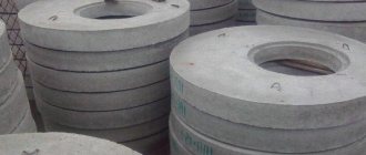
Reinforced concrete poles used in lighting systems are strong and durable products used for lighting sidewalks, highways, warehouse sites, and areas of industrial enterprises. These reinforced concrete products, which replaced short-lived wooden poles, are made from heavy concrete using vibrocompression or centrifugation technologies. To strengthen structures, steel reinforcing bars with a profiled and smooth surface are used.
Advantages and disadvantages of concrete lighting poles
Reinforced concrete supports are widely used in cities, villages, towns, and outside populated areas due to a set of operational advantages:
- Long operational period. When using high-quality raw materials and following technological rules, such concrete products retain their performance characteristics for at least 50 years.
- Resistance to the appearance and development of corrosion. Steel reinforcement is treated with effective anti-corrosion compounds.
- Resistant to fire. Concrete belongs to the category of non-combustible building materials.
- Resistance to mold formation.
- Possibility of operation in areas with increased seismic activity.
- Low operating costs, the ability to repair the surface with a slight shedding of concrete.
- Standardized shapes and sizes.
Power line supports
Power transmission lines (PTLs) are one of the most important components of a modern electrical network. A power line is a system of energy equipment that extends beyond power plants and is designed to transmit electricity remotely through electric current.
Power lines are divided into cable and overhead. A cable power line is a power line made by one or more cables laid directly into the ground, cable ducts, pipes, or onto cable structures. An overhead power line (OHL) is a device designed to transmit and distribute electrical energy through wires located in the open air.
For the installation of overhead power lines, special structures are used - overhead power line supports. Power transmission line supports are special structures designed to hold the wires of overhead power lines at a given distance from the surface of the earth and from each other.
The system of overhead power transmission towers was developed at the beginning of the twentieth century, when the first powerful power plants began to appear, and it became possible to transmit electricity over long distances. Until the mid-twentieth century, rolling out wires for power transmission line supports took place on the ground. But this method of rolling had many disadvantages: the wire dragged along the ground received numerous damages and required repairs during the installation process. Small scratches and chips became the cause of corona discharge, leading to losses of transmitted energy.
In the fifties of the twentieth century, a special method for installing electrical wires was developed in Europe - the so-called traction method. The pulling method involves rolling out the wire directly onto installed power line supports using special rollers, without lowering the wire to the ground. A tension machine is installed at one end of the overhead line, and a brake machine at the other. Thanks to this method, during the construction of power lines, the possibility of damage to electrical wires was significantly reduced and repair costs were reduced, which, in turn, led to a reduction in losses of transmitted electricity. The advantage of this method is also expressed in the fact that the presence of natural (rivers, lakes, forests, mountains, etc.) and artificial (roads, railways, buildings, etc.) barriers facilitates and speeds up the installation of power lines. In Russia, the technology for installing power transmission line supports “under tension” has been used since 1996 and is currently the most appropriate and popular method for constructing overhead power line supports.
In modern construction, power transmission line supports are also used as supports for holding grounded lightning rods and fiber optic communication lines. They are also used to illuminate spaces on highways, streets, squares, etc. in the dark. Overhead line supports are designed for the construction of power lines at a design outdoor temperature of up to -65˚C inclusive.
Precast concrete supports are divided into two main groups, depending on the method of hanging wires:
- intermediate power transmission line supports. The wires on these supports are secured in supporting clamps;
- anchor type supports. The wires on anchor-type supports are secured in tension clamps. These supports are used for tensioning wires.
Two main groups are divided into types that have special purposes:
- intermediate straight supports. They are installed on straight sections of the line and are intended to support wires and cables and are not designed for loads from the tension of wires along the line. On intermediate supports with suspended insulators, the wires are fixed in special supporting garlands, which are located vertically. On supports with pin insulators, the wires are secured by wire knitting. Intermediate straight supports perceive horizontal loads from wind pressure on the wires and on the support, and vertical loads from the weight of the wires and the own weight of the power line support;
- intermediate corner supports. They are installed at the angles of rotation of the line with wires suspended in supporting garlands. In addition to the loads that act on intermediate straight supports, intermediate supports also perceive loads from the transverse components of the tension of wires and cables;
- anchor corner supports. They are installed at power line rotation angles of more than 20˚, have a more rigid structure than intermediate corner supports and are designed for significant loads;
- anchor supports. Special anchor supports are installed on straight sections of the route for crossing engineering structures or natural barriers. Perceive longitudinal load from the tension of wires and cables;
- end supports. They are a type of anchor supports, installed at the end or beginning of power lines and are designed to absorb loads from one-sided tension of wires and cables;
- special supports, which include: transpositional - used to change the order of wires on the supports; branch lines - for installing branches from the main line; cross - used when overhead lines intersect in two directions; anti-wind - to enhance the mechanical strength of overhead lines; transitional - when crossing overhead lines through engineering structures or natural barriers.
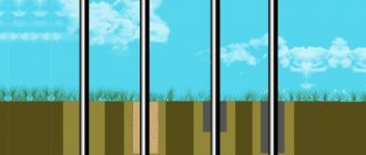
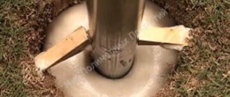
According to the method of fixation into the soil, pores are divided:
- supports installed directly into the ground;
- supports installed on foundations: regular, with a wide base of more than 4 m², and narrow-base (less than 4 m²).
By design, power line supports are divided into:
- free-standing supports. In turn, they are divided into single-column
and
multi-column
; - supports with guys;
- emergency reserve cable-stayed supports.
Transmission line supports are divided into supports for lines with voltages of 0.4, 6, 10, 35, 110, 220, 330, 500, 750, 1150 kV. These groups of supports differ in size and weight. The greater the voltage passing through the wires, the higher and heavier the support. The increase in the size of the support is caused by the need to obtain the required distances from the wire to the body of the support and to the ground, corresponding to the PUE (Electrical Installation Rules) for different line voltages.
Based on the material used, power transmission line supports are divided into wooden, metal and reinforced concrete. The choice of the type of power transmission line supports is usually based on the availability of appropriate materials in the area where the power line is being built, economic feasibility and technical characteristics of the facility under construction. Wooden poles are used for lines with low voltage, up to 220/380 V. However, despite such advantages as low cost and ease of manufacture, wooden poles have significant disadvantages: wooden poles are short-lived (service life is 10 - 25 years) and do not have high strength , the material reacts sharply to changes in climatic conditions.
Metal supports are much stronger than wooden ones, but require constant maintenance - the surface of the structures and connecting elements must be periodically painted or galvanized to prevent oxidation or corrosion.
High strength and resistance of the material to deformation, corrosion and sudden climate changes, long service life of structures (about 50-70 years), fire resistance, high manufacturability and low cost are some of the few reasons that allow us to say: reinforced concrete is the most appropriate solution for production power transmission line supports in Russia. Indeed, in a country with a huge area and varied climate, there is a need not only for a large number of long communication lines, but also for high reliability in conditions of sudden changes in weather conditions and humidity levels. The availability of high-quality reinforced concrete supports for power lines is the most important condition for ensuring stability in the operation of the electric power industry. The group produces and supplies to the construction market only high-quality reinforced concrete products, in strict accordance with GOST and SNiP.
Reinforced concrete pillars of power transmission line supports are divided into two types according to the manufacturing method.
- vibrating support struts. A manufacturing method in which the concrete mixture is subjected to vibration during pouring into a mold, which ensures an increase in the density and uniformity of concrete with less cement consumption. They are made from both prestressed and non-stressed reinforced concrete and are used as racks and struts in power transmission line supports with voltages up to 35 kV, as well as lighting supports;
- centrifuged support struts. A method of preparing a concrete mixture that ensures that the mixture is evenly distributed, hence each area is completely compacted. Centrifuged pole stands are intended for power lines with voltages of 35-750 kV.
Structurally, reinforced concrete power transmission line supports are elongated racks with different sections depending on the expected operating conditions and loads. The design of the support racks also assumes the presence of embedded parts for installing clamps, traverses and fastenings for rigid or hinged fastening of wires, as well as crossbars and plates to increase the load-bearing function of products.
According to the type of construction, reinforced concrete supports are divided into the main types:
- cylindrical support struts;
- conical support posts.
Reinforced concrete power transmission line supports come in a wide range.
For high-voltage power lines, centrifuged cylindrical and conical supports are manufactured in accordance with GOST 22687.2-85 “Cylindrical reinforced concrete centrifuged racks for supports of high-voltage power lines” and GOST 22687.1-85 “Cylindrical reinforced concrete centrifuged racks for supports of high-voltage power lines”, respectively.
Vibrating racks are manufactured in accordance with GOST 23613-79 “Reinforced concrete vibrating racks for supports of high-voltage power lines. Technical conditions", GOST 26071-84 "Reinforced concrete vibrating racks for supports of overhead power lines with a voltage of 0.38 kV. Technical specifications" and series 3.407.1-136 "Reinforced concrete supports of 0.38 kV overhead lines" and 3.407.1-143 "Reinforced concrete supports of 10 kV overhead lines".
Special two-post supports are manufactured in accordance with series 3.407.1-152 “Unified designs of intermediate two-post reinforced concrete supports of 35-500 kV overhead lines.” Series 3.407.1-157 “Unified reinforced concrete products for 35-500 kV substations” includes vibrating conical racks with a rectangular cross-section and centrifuged cylindrical racks. Series 3.407.1-175 “Unified designs of intermediate single-column reinforced concrete supports for 35-220 kV overhead lines” contains instructions for the production of conical support struts.
Reinforced concrete centrifuged supports for overhead contact networks and lighting are manufactured according to series 3.507 KL-10 “Supports for overhead contact networks and lighting.”
The material used for the manufacture of reinforced concrete pillars of power transmission line supports is Portland cement, which is resistant to electrical corrosion and corrosion from environmental influences, of various classes of compressive strength, from B25. Fine sand and crushed gravel are used as fillers. For each project, a different option for preparing the concrete mixture is selected: vibration is used for poles of power transmission lines with voltages up to 35 kV and lighting poles, centrifugation is used for poles of power lines with voltages of 35-750 kV. Concrete grades for frost resistance and water resistance are assigned depending on operating conditions and climate in the construction area, from F150 and W4, respectively. Additionally, special plasticizing and gas-entraining additives are added to the concrete of the support posts.
The concrete of power transmission line poles is reinforced with prestressed reinforcement to give greater strength to the products. All reinforcement parts and embedded products are necessarily coated with a special substance against internal corrosion.
The following classes of steel are used as working reinforcement:
- rod thermally strengthened periodic profile class At-VI according to GOST 10884-71 when operating racks in the construction area with a design outdoor temperature of not lower than -55°C;
- hot-rolled rod of periodic profile of classes A-IV and A-V. When the design temperature of the outside air is below -55°C, steel of these classes should be used in the form of whole rods of measured length. Class B-I reinforcing wire is used as transverse reinforcement. For the manufacture of clamps, grounding conductors and mounting loops, hot-rolled smooth reinforcing steel of class A-I is used.
Marking of racks according to GOST 23613-79.
In the designation of the brand of the stand, the letters and numbers mean: SV - vibrating stand; additional letters “a” and “b” - options for the design of the stands, where:
- “a” - the presence in the racks of embedded products (pins) and holes for fastening wires;
- “b” - presence of holes in the racks for fastening anchor plates;
- the number after the letters is the length of the stand in decimeters;
- the number after the first dash is the calculated bending moment in ton-force meters;
- the number after the second dash is the design grade of concrete for frost resistance.
For racks made of sulfate-resistant cement, the letter “c” is placed after the design grade of concrete for frost resistance.
For racks intended for use in areas with a design outside air temperature below -40°C or in the presence of aggressive soils and groundwater, the third group of brands also includes the corresponding designations of characteristics that ensure the durability of the racks under operating conditions: M - for racks used in areas with an estimated outside temperature of -40°C;
For racks used in conditions of exposure to aggressive soils and groundwater - characteristics of the degree of concrete density: P - increased density, O - especially dense.
According to GOST 22687.1-85 and GOST 22687.2-85, the rack brand consists of alphanumeric groups separated by a hyphen.
The first group contains the designation of the standard size of the rack, including:
letter designation of the rack type, where:
- SK - conical;
- SC - cylindrical;
- Next, the length of the stand is indicated in meters in whole numbers.
The second group includes designations: the bearing capacity of the rack and the scope of its application in the support and the characteristics of prestressed longitudinal reinforcement:
- 1 - for reinforcing steel class AV or At-VCK;
- 2 - the same, class A-VI;
- 3 - for reinforcing ropes of class K-7 with mixed reinforcement;
- 4 - the same, class K-19;
- 5 - for reinforcing ropes of class K-7;
- 0 - for reinforcing steel class A-IV or At-IVK.
In the third group, if necessary, additional characteristics are reflected (resistance to aggressive environments, the presence of additional embedded products, etc.).
Marking according to series 3.407.1-136 for the designs of 0.38 kV overhead line support elements consists of an alphanumeric designation.
The first part indicates the designation of the type of power line support:
- P - intermediate;
- K - terminal;
- UA - corner anchor;
- PP - transitional intermediate;
- POA - transitional branch anchor;
- PC - cross.
The second part shows the standard size of the support: odd numbers for single-circuit supports, even numbers for eight- and nine-wire overhead lines.
Marking according to series 3.407.1-143 for 10 kV overhead line supports has in the first part a letter designation of the type of support:
- P - intermediate;
- OA - branch anchor;
- Etc.
In the second part there is a digital index 10, indicating the overhead line voltage.
In the third part, separated by a dash, the number of the standard size of the support is written.
The elements of the supports, which include slabs and anchors, are marked with an alphanumeric designation. P - slab, AC - cylindrical anchor.
The product size number is indicated through a hyphen.
The marking of reinforced concrete intermediate single-post supports according to series 3.407.1-175 and double-post supports according to series 3.407.1-152 consists of an alphanumeric designation.
The first digit indicates the serial number of the region in which the support is used;
The following combination of letters is the type of support:
- PB - intermediate concrete;
- PSB - intermediate special concrete;
- The next group of numbers is the voltage of the overhead line in kV, within the dimensions of which the support is made;
- The number next after the dash is the serial number of the power line support, in the unification, with odd numbers belonging to single-circuit supports, and even numbers to double-circuit ones.
Marking of support products according to series 3.407.1-157:
The first group of alphanumeric designation includes letters of the conventional name of products and main overall dimensions in decimeters, where:
- SCP - cylindrical hollow stand;
- BC - vibrating stand.
The second group, separated by a hyphen, indicates the load-bearing capacity in kN.m;
The third group, separated by a hyphen, denotes design features (reinforcement option, the presence of additional embedded parts).
The marking of supports of the 3.407-102 series includes the following names:
- SCP - cylindrical hollow stand;
- BC - vibrating stand;
- VSL - vibrating stand for lighting lines and railway networks;
- Next comes a number indicating the standard size of the product.
Marking of reinforced concrete supports for overhead contact network and lighting according to series 3.507 KL-10 consists of alphanumeric designations.
Centrifuged power line supports (issue 1-1):
- OKTs - outdoor lighting poles with power supply cables;
- OAC - anchor supports for external lighting with air supply;
- OPTs - intermediate supports of external lighting with air supply;
- OSC - combined contact network and outdoor lighting supports with power supply cables.
The first number after the letters, separated by a hyphen, indicates the horizontal standard load on the support in centners, the second - the length of the support in meters.
Vibrating supports (issues 1-2, 1-4, 1-5):
- SV - vibrating outdoor lighting stand with cable or air power supply;
- The number following the letters indicates the standard bending moment in the embedment, in tm;
- The second number, separated by a hyphen, indicates the length of the rack in meters.
Unstressed vibrating struts (issue 1-6):
- The first group contains a letter designation of the type of structure, SV - vibrating stand, and a numerical designation - the length of the stand in decimeters;
- The second group is a symbol for bearing capacity.
Cons of concrete lighting poles
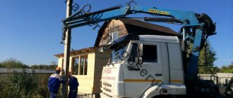
- Considerable mass. These supports are heavier than metal structures that have the same applications. The large mass of reinforced concrete products makes loading, unloading and installation work difficult. Their transportation requires heavy-duty vehicles.
- Monotonous appearance. In this regard, metal supports stand out because they can be made in various styles, complemented with decorative elements, and painted in colors that match the overall design of the area.
- Weak resistance to sharp impacts.
Today, instead of heavy reinforced concrete supports, metal and modern composite products are used.
Features of operation of reinforced concrete supports
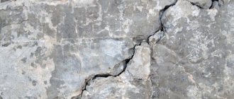
To protect steel supports from corrosion, hot galvanizing or treatment with special compounds is sufficient. Unlike metal supports, reinforced concrete structures are not prone to rust, but are able to absorb water from the ground. In winter, concrete saturated with moisture freezes, and in spring and autumn it thaws. During the year, in the central regions of Russia, up to 40-70 cycles of air temperature transition through 0 °C are observed. Under such influences, reinforced concrete supports quickly collapse and become unusable.
Various reagents that are used to clear roads and sidewalks of snow and ice also contribute to frost destruction of supports. To ensure a long service life of reinforced concrete supports, it is necessary to pay attention to the compliance of the grade with frost resistance and operating conditions. To increase the strength and resistance of supports to low temperatures and chemical components, special modifying additives are used. The resulting concrete structures have a higher frost resistance grade, but are comparable in cost to metal supports.
Therefore, when choosing between metal supports and reinforced concrete supports for installing street lamps, you need to consider the following:
- the amount of costs for installation, maintenance and disposal of supports;
- required level of security;
- difficulty in transporting supports to the installation site (transporting metal supports is easier and cheaper).
Important factors are also the temperature regime in winter, the height of the groundwater and the moisture content in the soil.
Types of concrete outdoor lighting poles
The main classification characteristics of these concrete products:
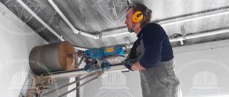
- Production method: vibration pressing and centrifugation.
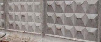
- Longitudinal shape – cylindrical, conical, prismatic, pyramidal.
- Cross-sectional shape - circle, rectangle, trapezoid, octagon.
- Solid cross-section or with internal cavity.
- The grade of concrete used in the production of reinforced concrete products. The introduction of special additives increases the water resistance, frost resistance of the material, and resistance to aggressive substances, which makes it possible to manufacture products that are maximally adapted to specific operating conditions.
- Type of reinforcement. Unstressed and stressed steel reinforcing bars are used to strengthen the structure. The method of reinforcement determines the bearing capacity of the support.
Characteristics and types
Lighting poles made of reinforced concrete are made by centrifugation and vibrocompression using concrete with various additives. To increase strength, the supports are reinforced with reinforcement - smooth or corrugated metal rods of different diameters.
Lighting poles are available in several brands, which differ in weight, height and design features. The supports can be monolithic or hollow, and in shape - round, octagonal and trapezoidal.
The choice of a specific option for reinforced concrete supports depends on the technical parameters and location of the lighting line, and is determined by the design documentation.
Varieties
Brands of concrete supports
| Marking | Weight, tons | Height, m | Section |
| SCC | 0,7—1,05 | 9—11 | Round (conical) |
| START (SV) | 0,8—3,5 | 9,5—16,5 | Trapezoid |
| SVN © | 0,8—1,7 | 9—10,5 | Octagonal |
| STS (SNTs) | 0,7—1,05 | 9—11 | Ring |
Types of pillars
- Power. Supply of current through overhead lines.
- Non-power. The electrical cable is laid underground. Maximum height - 12 m.
Lamps - spotlights
Here we will not consider in detail what kinds of street lamps and spotlights there are, but in order for the installation to go smoothly, it is important to know this: The bracket should be inserted into the console lamp without any problems. Therefore, when ordering a bracket, indicate the diameter of the mounting hole of the lamp, or exactly the opposite, when buying a lamp, make sure that it will fit your bracket. The bracket for the spotlight has a different design. The spotlight has a lyre (U-shaped bracket) that can be mounted on any surface (wall, ceiling, floor); in case of installation on a support, a bracket with a flat surface is required. When ordering a bracket, you need to know its width and the distance between the mounting holes located on the lyre. If there are several spotlights, then also in which directions they will be directed.
That’s why we recommend buying all the elements of the lighting installation in one place, from us at MEGATRON Electrics.
go to the section of cantilever street lamps of lamp housing and communal services GKU go to the section of LED street console lamps DKU go to the section of lamp street spotlights ZHO GO go to the section of LED street spotlights DO
Advantages of reinforced concrete pillars
Power line supports made of reinforced concrete have:
- High strength. They can easily withstand not only strong wind loads, but also impacts from collisions with cars and other vehicles;
- One hundred percent environmentally friendly. There are no materials in the design that, under changing humidity and temperature or under the influence of the sun, release substances harmful to humans into the air;
- Service life – 100-150 years;
- Minimum financial and labor costs for repair work;
- Dielectric properties.
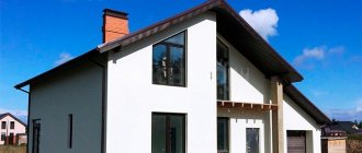
Electrical supports are an element of the architecture of cities, towns and transport interchanges. Not the most presentable appearance does not repel. It is clear that their main task is to create safe conditions for the transportation of electricity.