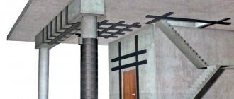
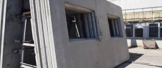
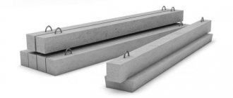
In newly built houses, cracks appear due to the influence of certain factors. Expansion joints in reinforced concrete structures, shrinkage, sedimentation and others are called deformation joints, and are the prevention of these undesirable consequences that occur in seismic zones, areas with large amplitudes of temperature changes, and in buildings built on different types of soil or on mountainous terrain.
An expansion joint is intended to reduce the load on parts of structural elements in areas of probable deformation.
Temperature shrinkage joints in reinforced concrete structures SP
SNiP 2.03.04-84 ________________ Registered by Rosstandart as a joint venture 27.13330.2010
. — Note from the database manufacturer.
BUILDING REGULATIONS
CONCRETE AND REINFORCED CONCRETE STRUCTURES DESIGNED FOR WORK UNDER CONDITIONS OF IMPACT OF ELEVATED AND HIGH TEMPERATURES
____________________________________________________________________ Text Comparison of SNiP 2.03.04-84 with SP 27.13330.2011 cm. link. — Note from the database manufacturer. _____________________________________________________________________
DEVELOPED BY NIIZhB of the State Committee for Construction of the USSR (Doctor of Technical Sciences, Prof. A.F. Milovanov, topic leader; Candidates of Technical Sciences V.N. Goryachev, V.M. Milonov, V.N. Syamoilenko) with the participation of VNIPI Teploproekt of the USSR Ministry of Montazhspetsstroy (V.A. Tarasova), Makeyevsky Institute of Scientific Research of the Ministry of Higher Education of the Ukrainian SSR (Candidate of Technical Sciences A.P. Krichevsky), Kharkov Industrial Construction Project of the State Committee for Construction of the USSR (Candidates of Technical Sciences I.N. Zaslavsky, S.L. Fomin).
INTRODUCED BY NIIZhB of the USSR State Construction Committee.
PREPARED FOR APPROVAL BY Glavtekhnormirovanie Gosstroy USSR (V. M. Skubko).
With the entry into force of SNiP 2.03.04-84 “Concrete and reinforced concrete structures intended for operation in conditions of exposure to elevated and high temperatures”, from January 1, 1986, the “Instructions for the design of concrete and reinforced concrete structures intended for operation in conditions of exposure to elevated and high temperatures" (SN 482-76).
When using a regulatory document, you should take into account the approved changes to building codes and regulations and state standards published in the journal Bulletin of Construction Equipment of the USSR Gosstroy and the information index State Standards of the USSR Gosstandart.
These norms and rules apply to the design of concrete and reinforced concrete structures intended for operation under conditions of systematic exposure to elevated (from 50 to 200 ° C inclusive) and high (over 200 ° C) process temperatures (hereinafter referred to as temperature exposure).
The standards establish requirements for the design of these structures made from structural heavy concrete with an average density of 2200 to 2500 inclusive (hereinafter referred to as ordinary concrete) and from heat-resistant concrete of a dense structure with an average density of 900 or more.
The requirements of these standards do not apply to structures made of heat-resistant concrete of a cellular structure.
Reinforced concrete chimneys, tanks and foundations of blast furnaces operating at temperatures above 50°C should be designed taking into account the additional requirements imposed on these structures by the relevant regulatory documents.
The main letter designations adopted in these standards in accordance with ST SEV 1565-79 are given in reference Appendix 1.
GENERAL INSTRUCTIONS
1.1. Concrete and reinforced concrete structures intended to operate under conditions of exposure to elevated temperatures should, as a rule, be made of ordinary concrete.
Foundations that, during operation, are constantly exposed to temperatures up to 250°C inclusive, may be made of ordinary concrete.
Concrete and reinforced concrete structures intended to operate under high temperatures should be made of heat-resistant concrete.
Load-bearing structural elements of thermal units made of heat-resistant concrete, the cross-section of which can be heated to temperatures above 1000°C, may be accepted only after they have been tested experimentally.
Heat-resistant concrete in structural elements of thermal units should be used in accordance with recommended Appendix 2.
Classes of heat-resistant concrete according to the maximum permissible temperature of use in accordance with GOST 20910-82*, depending on the type of binder, fillers, finely ground additives and hardener are given in Table. 9. __________________ * The document is not valid on the territory of the Russian Federation. GOST 20910-90 is valid, hereinafter in the text. — Note from the database manufacturer.
1.2. For structures operating under the influence of temperatures above 50°C under conditions of periodic humidification with steam, process water and condensate, it is necessary to comply with the requirements of paragraphs. 1.8, 2.4, 2.6 - 2.8, 2.11 and 5.7. If it is impossible to meet the specified requirements, the calculation of such structures is allowed only for the effects of temperature and load, without taking into account periodic humidification. In this case, the calculation of the cross-section should not take into account the outer layers of concrete 20 mm thick on each side, subject to soaking for 7 hours, and 50 mm thick if the concrete was soaked for more than 7 hours, or the concrete surface should be protected from periodic soaking.
The painted concrete surface or waterproofing coatings of these structures should be light in color.
1.3. Cyclic heating is a long-term temperature regime in which, during operation, the structure is periodically subjected to repeated heating with temperature fluctuations of more than 30% of the design value with cycle durations from 3 hours to 30 days.
Constant heating is a long-term temperature regime in which during operation the structure is subjected to heating with temperature fluctuations of up to 30% of the calculated value.
1.4. When designing structures made of heat-resistant concrete in accordance with GOST 20910-82, it is necessary to take into account additional requirements for source materials for heat-resistant concrete, the selection of their composition and preparation technology, as well as the specifics of performing work in accordance with the requirements of SN 156-79.
determine the cause of freezing and leaking panel seams.
We will carry out comprehensive work on sealing and repairing interpanel seams of the entire building or problem areas of the building facade.
Before starting work, a specialist will visit the site to inspect and select materials.
We will select materials for sealing seams based on the type of joints, weather conditions and the wishes of the customer.
The work will be carried out using industrial mountaineering technologies or traditional work methods (scaffolding, cradles).
Our climbers have been trained in specialized training centers, are proficient in construction specialties, and most importantly, have extensive practical experience in sealing interpanel joints in buildings.
BASIC CALCULATION REQUIREMENTS
1.5. Concrete and reinforced concrete structures operating under conditions of exposure to elevated and high temperatures should be calculated based on the provisions of SNiP 2.03.01-84, taking into account additional requirements set out in these norms and rules.
When calculating concrete and reinforced concrete structures, it is necessary to take into account changes in the mechanical and elastoplastic properties of concrete and reinforcement depending on the impact temperature. In this case, forces, deformations, formation, opening and closing of cracks are determined by the influence of load (including its own weight) and temperature.
Design schemes and basic prerequisites for the calculation of concrete and reinforced concrete structures must be established in accordance with the conditions of their actual operation in the limit state, taking into account, if necessary, the plastic properties of concrete and reinforcement, the presence of cracks in tensile concrete, as well as the influence of shrinkage and creep of concrete as in normal conditions. temperature, and when exposed to elevated and high temperatures.
1.6. Calculation of structures operating under conditions of elevated and high temperatures must be carried out for all possible unfavorable combinations of loads from their own weight, external load and temperature, taking into account the duration of their action and, if necessary, cooling.
Calculation of structures taking into account the effects of elevated and high temperatures must be carried out for the following main design stages of work:
short-term heating - the first heating of the structure to the design temperature;
long-term heating - exposure to the design temperature during operation.
Calculation of statically determinable structures based on the limit states of the first and second groups (with the exception of calculations for the formation of cracks) should be carried out only for the stage of long-term heating. Calculations for the formation of cracks must be made for the stages of short-term and long-term heating, taking into account the forces arising from the nonlinear distribution of concrete temperature along the height of the element section.
Calculation of statically indeterminate structures and their elements according to the limit states of the first and second groups should be carried out:
a) for short-term heating of the structure according to the regime in accordance with SNiP III-15-76*, when the greatest forces arise from the influence of temperature (see clause 1.10). In this case, the rigidity of the elements in the structure is determined according to the instructions in paragraphs. 4.17 and 4.18 as a function of short-term action of all loads and depending on the heating rate; _____________________ * The document is not valid on the territory of the Russian Federation. SNiP 3.03.01-87 is in force. — Note from the database manufacturer.
b) for long-term heating - the impact on the structure of the design temperature during the period of operation, when the strength and rigidity of elements decreases as a result of exposure to prolonged heating and load.
In this case, the rigidity of the elements is determined according to the instructions in paragraphs. 4.17 and 4.18 as from prolonged exposure to all loads.
The calculated process temperature is assumed to be equal to the temperature of the workshop environment or working space of the thermal unit specified in the design assignment.
Design forces and deformations from short-term and long-term heating are determined taking into account the safety factor for temperature according to the instructions in clause 1.27.
1.7. The magnitudes of loads and impacts, the values of reliability factors, combination factors, as well as the division of loads into permanent and temporary long-term, short-term, special should be taken in accordance with the requirements of SNiP II-6-74, taking into account additional instructions SNiP 2.03.01-84.
Loads and temperature effects taken into account when calculating the structure according to the limit states of the first and second groups should be taken according to Table. 1 and 2.
When calculating strength, where necessary, special loads must be taken into account with load safety factors adopted according to the relevant regulatory documents. In this case, forces caused by temperature are not taken into account.
1.8. The crack resistance of structures (or their parts) must meet the requirements of SNiP 2.03.01-84, taking into account the additional instructions of this paragraph.
Categories of requirements for crack resistance of reinforced concrete structures, depending on their operating conditions, type of reinforcement, as well as the maximum permissible crack opening width, taking into account the effect of temperature on elements operated in a non-aggressive environment, to ensure the safety of reinforcement, are given in Table. 3.
1.9. Determination of forces in statically indeterminate structures from external load, self-weight and exposure to elevated and high temperatures is carried out according to the rules of structural mechanics by the method of successive approximations. In this case, the rigidity of the elements is determined taking into account inelastic deformations and the presence of cracks in concrete from the simultaneous action of external load, own weight and temperature.
1.10. During short-term heating, the forces from the influence of temperature in the elements of statically indeterminate structures should be determined depending on the composition of the concrete (see Table 9) and the heating temperature that causes the greatest forces:
a) when heating concrete No. 1 from above 50 to 250 ° C - according to the design temperature;
b) when heating concrete No. 2-11, 23 and 24 over 200 to 500 ° C at the design temperature; when heated above 500°C - at 500°C;
c) when heating concrete No. 12-21, 29 and 30 over 200 to 400°C - at the design temperature, when heating over 400°C - at 400°C.
For structures located in the outside air, the calculation of the greatest forces from the influence of temperatures is carried out according to the design air temperature as required by clause 1.40.
Static design diagram
and calculation stage of work
Loads and load safety factors
, temperature effects and temperature safety factors taken in the calculation
Features and purpose
The structure is divided into independent blocks using shrinkage joints , which makes the entire structure more elastic. The joints are sealed with flexible insulating material.
Structures made of reinforced concrete are deformed under the influence of temperature changes and can shrink or expand. Shrinkage of concrete also leads to shortening of the material. Displacement of structural elements occurs at any vertical settlement.
Most reinforced concrete structures are statically indeterminate, and when the concrete and foundation settle and temperature changes, forces appear, leading to cracks and changes in the structure of the structure.
Maximum gap between seams
Shrinkage and temperature calculations are not carried out for standard structures and those with crack resistance of the third category, if the joint distance is less than the established limits.
Deformation gaps can be located vertically and horizontally. Without calculations in monolithic structures, distances between expansion joints are acceptable if they correspond to the following parameters:
- Frame prefabricated structures, including elements made of wood and metal: 60 m for heated and 40 m for outdoor buildings.
- Solid prefabricated: 50 m for insulated and 30 m for unheated structures.
- Solid frame buildings made of heavy concrete: 50 m and 30 m, from light concrete - 40 m and 25 m.
- Solid monolithic structures made of solid composition: 40 m and 25 m, from cellular - 30 m and 20 m.
The size of blocks in a reinforced concrete structure is determined by the standards established by the following reference materials:
- Clause 1.17 SNiP 2.03.04−84, clause 6.27 SP 27.13330.2011, SP 52−110−2009.
- Manual clause 1.19 (1.22) to SNiP 2.03.01−84. Here the characteristics of the building are taken into account. Heated structures made of monolithic reinforced concrete can have a block length of up to 90 m.
- Addition to SNiP 2.08.01−85. Paragraphs 1.16 and 1.18 from Issue 3 on the design of residential buildings.
In reinforced concrete monolithic structures, expansion joints with crack resistance categories 1 and 2 have their own placement features:
- Without exception, they are installed after calculations for the crack resistance of the structure.
- They are placed on the building along the entire height, which allows deformation to occur freely in individual parts of the structure. The seams run from the top of the foundation to the beginning of the roof, separating walls and possible ceilings.
- The standard seam width is 2−3 cm, it
- filled with several layers of roofing felt, tow, impregnated with resin or roofing felt.
Installing paired beams on two columns provides an optimal and correct expansion joint in monolithic and prefabricated structures. In frame structures it is more convenient when dynamic and large loads occur on the floor elements.
The placement of sediment separators is necessary between building elements located on soils of different heights and qualities. In this case, they also pass through the foundation. In reinforced concrete structures, shrinkage-temperature joints are also required if a connection is made between an old building and a new extension.
Sliding pairs of columns apart with support on separate foundations and installing opposing beam consoles allows you to create an optimal quality deformation separator. You can place between parts of the building an inset span created from beams and slabs.
All presented options eliminate the destruction of building materials and increased load on individual structural elements.
In monolithic buildings, the following formation of a shrinkage joint is possible: the end of the beam from one part of the structure rests freely on the console, which is a continuation of the crossbar of the other part of the building. Contacting elements must be connected as carefully as possible so that their friction does not lead to destruction of the consoles.
Examples of nodes
Shrinkage joints are also provided in tunnels and channels . The gap between them is calculated (its minimum length should be 50 m).
The settlement weld keys are installed according to the design documents. A gap of 20 mm is left between them and the reinforcement. Installation is carried out using wire at a distance of 250 mm.
Cyanoacrylate glue is used along the entire length to fix the dowels. Rubber serves as reinforcement. After installing the keys, you need to draw up an acceptance certificate for internal work with the material. All further manipulations provide for the preservation of the seam structure.
The placement of expansion joints helps protect building structures from destruction and distortion. Their correct location significantly increases the service life of reinforced concrete structures and preserves the quality of the material.
Protecting the blind area
So, to make expansion joints in the blind area, you need to:
- Dig a trench along the petimeter of the building. Its depth should be 15 cm. The width of the trench should be greater than the roof canopy;
- Fill the bottom of the trench with a cushion of crushed stone, and lay roofing material on top along the entire perimeter;
- Install the frame based on the reinforcement.
Before moving on to concrete work on the blind area, we will make a protective seam. It should be done on the line where the walls and the blind area connect. To organize a groove, it is enough to install boards of small thickness between the blind area and the wall. These grooves are also necessary across. This is done using the same method. You need to maintain a distance of 1.5 m.
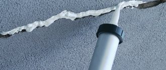
After pouring, the concrete mixture will go where it is needed, but there will be grooves where the boards are installed. After the solution has sufficiently hardened, the wood can be pulled out. The cracks can be sealed with sealant or other means. The most important thing is that the cuts are not empty, otherwise there will be zero protection.
How to make an expansion joint in reinforced concrete monolithic and prefabricated structures
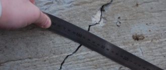
An expansion joint in reinforced concrete structures is performed to relieve pressure on elements in areas where the material can deform under the influence of various negative factors.
Most often, the original state of reinforced concrete is violated due to strong temperature fluctuations, in the presence of focal shrinkage of the soil, in places with high seismic activity, and in other situations when unsafe loads are observed that significantly reduce the load-bearing functions of the monolith.
What is an expansion joint
Expansion joints are the division of the building structure into fragments in the horizontal (vertical) plane provided for by the project, thanks to which it is possible to compensate for stress in certain areas of the load-bearing frame. If this stress is not eliminated, the geometric dimensions, position, and properties of reinforced concrete may change significantly.
Thanks to the seams, it is possible to give buildings the design value of elastic mobility. Expansion joints come in different types depending on the type of stress they are designed to compensate for: seismic, sedimentary, structural, shrinkage joints, temperature.
When an expansion joint is made, the structure is divided into separate blocks, giving the monolith elasticity and the ability to withstand severe loads without deformation. The joints are sealed with a special insulating material, which must be flexible and resistant to various influences.
Visually, expansion joints in monolithic reinforced concrete are cuts in the surface that divide the structure into blocks of a certain size. Each seam has a task that it is designed to perform. A shrinkage joint is made in reinforced concrete screeds to prevent the formation of cracks on the surface as the concrete gradually hardens and gains strength.
Due to the location and design parameters, combinations of different types of seams can be used in buildings, which simultaneously protect against several causes of possible deformation. This approach is especially relevant in the construction of tall, extended buildings with a large number of different elements and structures.
Types of expansion joints in reinforced concrete structures:
- Temperature-deformation - protect against the effects of temperature surges and are often needed even where there is a temperate climate. Low temperatures in winter and high temperatures in summer lead to the appearance of cracks of different depths and sizes, which deform the foundation and frame. Expansion joints are made at a distance determined based on the material and design features, temperatures. Typically, seams are made only on walls.
- Shrinkage - performed less frequently, most often when creating a concrete monolithic frame. During the process of hardening and gaining strength, concrete can become covered with cracks that increase to cavities. When there are many cracks in the foundation, the structure may collapse. The seam is made before the base hardens; it grows throughout the entire time the concrete turns into a monolith, allowing it to shrink and not become covered with cracks.
- Seismic expansion joints are performed where there is a risk of earthquakes, landslides, tsunamis, and volcanic eruptions. The seams protect the house from destruction due to shocks from the ground. The seams are always created according to an individual project, creating separate vessels inside the structure without communication, divided along the perimeter by expansion joints. Quite often the diagram looks like a cube with identical faces. The edges are compacted with double brickwork and at the moment of shocks they must hold the structure.
- Sedimentary - most often used in buildings with a different number of floors (one wing of a building with two floors, another with three, for example). It turns out that parts of the building exert different pressure on the soil and it sags unevenly, putting pressure on the foundation and walls, causing cracks to appear. The sedimentary expansion joint strengthens the structure and protects against deformation. Performed vertically, from the base to the roof. Fixes different parts of the building. The seams must be filled with sealant.
When a sedimentary seam is necessary:
- Placing parts of a structure on soil with different properties
- When making extensions to an existing building
- If individual parts of the building have a difference in height of more than 10 meters
- All cases in which uneven foundation subsidence can be expected
Technology for sealing interpanel seams
Preparation of interpanel repair seams
Preparation includes cleaning the seam surface from old sealant, paint, and dirt. The edges are cleaned with a brush and degreased with a solvent.
Laying insulation
After preparation, heat-protective polyurethane sealant “Macroflex” is poured into the empty seam between the panels. When hardened, this sealant expands and fills all voids and cracks.
After pouring Macroflex, hollow insulation Vilaterm is applied to the not yet hardened polyurethane sealant with a compression of 15-30%.
Vilaterm is laid slightly deeper than the wall plane, the remaining groove is filled with sealant.
Laying sealant
The sealant is applied with a spatula and special spatulas.
The largest distances between expansion joints in reinforced concrete structures
Calculations for temperature indicators and shrinkage are not carried out for standard type structures with crack resistance of the third category with stressed/unstressed products, but provided that the distance between the seams is less than the standard limits. Expansion joints can be horizontal and vertical.
Optimal distances between seams (without calculation):
- For frame structures made of wood and metal - 40 meters for outdoor buildings, 60 meters for heated ones
- Prefabricated solid structures - 30 meters for unheated buildings and 50 meters for heated ones
- Monolithic frame structures made of heavy grades of concrete - 30 and 50 meters, respectively
- Frame monolithic structures made of lightweight concrete - 25 and 40 meters, respectively
- Monolithic buildings made of solid compounds - 25 meters for unheated premises and 40 for heated ones
- Cellular concrete - 20 and 30 meters respectively
If a one-story building is being erected from reinforced frame concrete, the distance between the seams can be increased by an average of 20% relative to the values in the table. Tabular data can be used when creating vertical connections in the middle of a separated block in frame buildings. Such connections are placed along the edges of the block and, when subjected to deformations, bring the work of the frame closer to a solid structure of a similar type.
Features of performing expansion joints:
- Performed in all buildings with crack resistance of the first and second categories.
- They pass along the entire height of the building, due to which deformation in individual zones of the structure occurs freely. Seams can run from the top of the base to the beginning of the roof, dividing the walls and all ceilings.
- The width of a standard seam is 2-3 centimeters; the seam is filled with tow impregnated with roofing felt or resin, several layers of roofing material, and sealant.
- Installation of paired beams on 2 columns guarantees the correct expansion joint in prefabricated and monolithic structures. In frame buildings it is comfortable when serious and dynamic loads appear on the floors.
- A sedimentary joint is needed when the building is at different heights or ground.
- A temperature-shrinkage joint is needed when connecting a new extension to an old structure.
- Sliding pairs of columns apart with support on separate bases, as well as installing counter beam consoles, make it possible to make a high-quality expansion joint. Also, often an inset span of slabs and beams is made between the individual parts of the building.
- In monolithic buildings, the shrinkage joint is formed as follows: from one part of the structure, the end of the beam rests freely on the console; it is a continuation of the crossbar of the other part of the structure. Elements that touch are connected carefully to avoid friction that destroys the consoles.
How are they performed?
Thermal and shrinkage (as well as seismic and sedimentary) types of seams can be combined in a design - a shrinkage-temperature (and seismic-sedimentation) seam is obtained. The first runs along the width and length of the building from the top of the foundation to the roof, while the second involves the complete division of the structure into blocks independent of one another.
In this case, the reinforced concrete box is divided into vertical joints 2-3 centimeters wide, filled with a hydrophobic elastic sealant. Proper release can be ensured by installation in adjacent areas of adjacent parts of paired beams and columns.
In buildings of different heights and on different soils, even if they are combined with an inset span, sedimentary joints are made. Thermal expansion in the blind area made of reinforced concrete is compensated by dividing it into two-meter squares by installing bitumen-impregnated wooden blocks in the formwork. The connection of the formwork to the walls must be movable and airtight.
Concrete floors deform if their area exceeds 30 square meters, causing cracks to spread. The surface of the screed is cut to a depth of a quarter to half the height so that the material breaks under the seams. Screed areas can be up to 6 meters in size and not only square, but also with an aspect ratio of 1:1.5. Joints of different materials and screeds poured at different times are made with dampers.
Insulating seams separate the screed from the walls to the full height along the perimeter of the building; they are filled with elastic materials. Columns and flights of stairs are also insulated from the floor screed. Monolithic floor slabs are separated by cuts from the supporting frame of the structure, the optimal width is calculated individually.
Interfloor ceilings are filled with fragments of a certain size. All voids are filled with sealant and sealed. They are divided along the entire height into separate blocks and strip bases, which compensate for stress and load.
Foundation cutting step: 30 meters on weak soils and 15 meters on heaving soils. The seams are filled with durable sealants. Vertical structures of external/internal walls create horizontal sections dividing the building into compartments. The height of the compartment for the interior wall is 30 meters, for the front wall – 20.
- In driveways/aisles, seams are made at a distance identical to the width of the screed (in the case where the passage is more than 3.6 meters, a longitudinal seam can be made in the center).
- The distance between seams in open areas is a maximum of 3 meters in all directions.
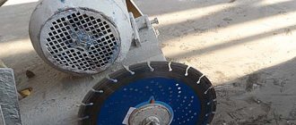
- Expansion joints are made using forming laths, otherwise the cuts are made after the final processing of the concrete.
- Standard screed joints are cut into 6x6 meter blocks one third of the thickness of the concrete layer.
- The location and number of seams are determined based on concrete shrinkage, thermal expansion coefficient, probable deformations at the junction of walls and floors, foundation and columns, etc.
- All seams must be sealed, based on operating conditions and requirements.
- Special rails can be used that fit into the frame at the pouring stage.
Reinforced concrete structures during operation can be subject to various loads and influences, which can be compensated for by making expansion joints.

