Application area
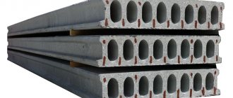
Reinforced concrete pipes are common in civil engineering.
They are most often used when laying septic tanks through which industrial and domestic wastewater migrate. Due to the fact that such pipes have a significant diameter, they are widely used when installing main sewers. They are indispensable when arranging storm sewer systems. Such pipes can have different profiles, which allows them to be used when installing various structures such as supports, foundations and much more.
Performance characteristics
The crack resistance test is considered passed if, under pressure, a chip of no more than 0.2 mm appears on the sample.
GOST determines the possibility of deformation and strength characteristics when laying pipes in a ditch. The strength of the pipe is calculated based on the depth of its installation. The regulatory official document describes the control voltage according to the following characteristics:
- Strength. This parameter characterizes the quality of a product that cannot withstand the load and does not perform its initially defined functions.
- Crack resistance. The indicator is considered normal if a chip of no more than 0.2 mm is detected on the surface of the pipe under pressure on the original sample. In this case, there is no loss of its performance indicators.
Types of reinforced concrete pipes
Reinforced concrete pipes are classified according to certain criteria. Thus, they can be non-pressure. Such products are used to transport liquids by gravity.
They cannot be used in conditions that involve significant liquid pressure. However, such pipes can withstand high mechanical loads and also have excellent strength characteristics. The second classification of reinforced concrete pipes is pressure products used in the installation of pipelines that operate under high loads in the form of internal pressure. This type of product is produced using a special technology, which involves crimping, which improves quality characteristics. Pressure reinforced concrete pipes have a large wall thickness, which sometimes reaches 10% in relation to the internal diameter. There are also special-purpose pipes, the diameter of which sometimes reaches 2 m with a length of 5 m. Such products are especially durable.
As for pressure pipes, they can have one of four pressure modifications (5-20 atmospheres); they are used for liquids that do not have an aggressive environment. Particularly common in production are products whose diameter is in the range of 40-160 cm. Reinforced concrete pipes are also classified according to their maximum laying depth. Three groups can be distinguished, each of which assumes a distance from the surface of the earth within 2, 4 and 6 m.
Production of concrete products
The production technology of products involves the use of moisture-resistant concrete and the use of reinforcement.
For the manufacture of elements, moisture-resistant and bioresistant grades of concrete are used, which are produced by vibration compaction with or without reinforcement (bar BP-1 and B1). Impurities are added to the cement paste to prevent fouling and rotting. The basic rules and standards of products are determined by GOST 6482–88, pressure ones are manufactured in accordance with GOST 24983–81. The length of such pipes varies up to 2.5 m, and the maximum diameter is up to 1.5 m. A concrete pipe is made in 3-12 minutes, it depends on the type of equipment and size. The laboratory must check the quality of the product and compliance with the output labels.
View "GOST 6482–88" or
View "GOST 24983-81" or
At the beginning of the production process, the mold is prepared, cleaned and lubricated. If the pipe is supposed to be reinforced, then iron rods are inserted in the form of a frame, then the bottom is installed and fixed. The structure is moved into a centrifuge, and a concrete solution is slowly supplied, which fills all the voids of the product. Next, it is sent to a steaming chamber to gain strength. Upon completion, the mold is disassembled into parts, and the finished pipe is transported to a warehouse. And there is also a 2nd production method - vibration compaction, which, after forming and applying vibration, enters the steaming chamber.
A non-pressure pipe is made with a special socket, which is located only on one side. This element is needed for joining products.
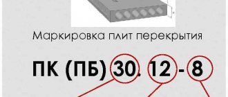
Marking of reinforced concrete products
In order to understand what products you have in front of you - reinforced concrete non-pressure socket pipes or others, you need to understand the markings. Thus, the first numbers that can be seen on non-pressure products equipped with a socket indicate the size of the internal section, the data is indicated in centimeters. Whereas from the second combination you can understand what the length of the pipe is; by the way, it is indicated in decimeters.
The last number is the load-bearing capacity, which indicates the permissible installation depth. If a reinforced concrete culvert pipe can be used when laying a pressure-type system, then it will have the letter abbreviation TN on it. If there is a side, sole or connecting point on the pipe, you can see the markings TB, TP, TS, respectively. But folded products may have the following markings: TF, TFP, TBFP, TO, TE and others.
Preparatory work before the start of construction
The installation of systems built from reinforced concrete pipes is preceded by a set of preparatory work, which includes the following stages:
- pipeline design taking into account the characteristics of the medium supply, calculation of economic efficiency and the choice in favor of pressure or free-pressure pipes, the method of their connection;
- marking the territory on the ground with the installation of signs for fastening the axes of the pipeline being built;
- laying out the right of way and forming temporary roads;
- soil preparation: digging trenches to the required size, eliminating structural interference, which involves removing boulders, uprooting trees and stumps;
- foundation arrangement. For long-term and trouble-free operation of pipelines, a necessary condition is the presence of tight support of reinforced concrete products on the bottom of the trench. Particular attention should be paid to preparation in cases where the pipeline crosses other types of communications;
- pipeline laying. The stage, as a rule, consists of accepting reinforced concrete pipes and carefully inspecting them for mechanical damage; deformations, chips and cracks. Defective products are not allowed to be used. After that, the pipes, in accordance with the design, are transported to the installation sites and left on the surface. Lowering of heavy products with large cross-sections is carried out using crane equipment, preventing arbitrary rolling. The manual laying process is only permissible for small diameters. Reinforced concrete pipes are lowered into trenches with vertical walls and installed with sequential removal of spacers. When installing free-flow pipes, the specified slope of communications is taken into account;
- suitability testing and flushing of the pipeline system.
- repeated sealing of seams in places of leaks;
- digging trenches;
- removal of temporary roads.
Advantages of reinforced concrete products
Reinforced concrete pipes, free-flow or pressure, have a lot of advantages, the first of which implies high strength and reliability of the products.
These qualities are due to special production technology. It is centrifugal casting that makes it possible to obtain such durable products. During manufacturing, vibration pressing is also used. Additional advantages of reinforced concrete pipes are their low cost, which is explained by not so high production costs; as well as the ability to withstand temperature changes.
In addition, the pipes can be operated over a wide temperature range. They can be used in harsh external conditions. Concrete does not corrode and does not rot, which makes consumers choose it much more often than steel. Among the advantages, experts highlight the dielectric properties of the material, this helps eliminate stray currents. Such products will last for more than half a century.
Main pros and cons
The undeniable advantage of this product is its long service life, at least 70 years. This durability is due to the resistance of concrete to adverse environmental influences, the absence of corrosion of reinforcing bars, and resistance to chemical and biological environments. Cost-effectiveness, strength, low price, ease of installation, short production time - these are the main qualities of concrete pipes. If necessary, already used pipes are re-laid, this does not affect the quality. Disadvantages include significant weight and insufficient strength compared to reinforced concrete products, and they cannot be used for transporting aggressive chemicals. Thinning of the walls and growths render the pipe unusable or require its removal for sanitization.
GOST 6482-88
Manufacturing standards are regulated by GOST: reinforced concrete pipes according to it must meet water resistance characteristics, in addition, they must undergo internal hydrostatic pressure within 0.05 MPa. Concrete must be frost resistant. In addition, the pipes must be based on heavy concrete, prepared in accordance with GOST 26633, its compressive strength must be equal to B25.
The mentioned compressive strength can be changed, but deviations that go beyond the scope of GOST 13015.0 are unacceptable. The water resistance of the pipe walls must correspond to class W4. Water absorption should not exceed 6% by weight. Steel A-I and A-III (GOST 5781) can be used as a reinforcement frame.
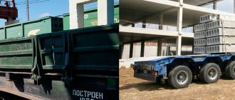
TRANSPORTATION AND STORAGE
4.1. Transportation and storage of pipes - in accordance with GOST 13015.4.
4.2. Pipes should be stored in a finished product warehouse in stacks sorted by grade.
Note. Pipes with a useful length of less than 5 m may be stored in a vertical position, provided that their stability is ensured.
4.2.1. The number of rows of pipes in height should not exceed that indicated in the table. 5.
Table 5
| Dу, mm | Number of rows of pipes in height |
| From 400 to 1000 incl. | 4 |
| 1200 | 3 |
| From 1400 to 2400 inclusive. | 2 |
4.2.2. Under the bottom row of pipes of the stack, two pads should be laid parallel to each other at a distance of 0.2 m of the pipe length from its ends. The design of the linings should not allow the bottom row of pipes to roll out.
Characteristics of reinforced concrete pipes
All quality characteristics of reinforced concrete pipes are regulated by the mentioned GOST; non-pressure reinforced concrete pipes should not have cracks on the walls, otherwise they cannot be used in work. An exception is shrinkage cracks, the width of which does not exceed 0.05 mm. Completeness is also determined by standards.
Thus, pipes that are marked TB, TSP, TBP, as well as TS must be sold and delivered to the buyer together with rubber-based sealing rings. Quality is also determined by the correctness of marking, this indicates that the manufacturer strictly followed the rules prescribed in GOST. The marking must be applied to the outer surface of the socket; the designation may also be on one end of the seam type pipe.
The diameters of reinforced concrete pipes were indicated above and are very diverse.
To install a particular system, you can select products with certain parameters. Don’t think that if you have to spend money on heavy equipment during installation, the system will be much more expensive than one that is based on pipes made of a different material. After all, concrete pipes can pay for themselves over their service life, without requiring repairs for a long time.
Reinforced concrete socket pipes are quite convenient to install, which is why they are used most often, but before installing the system yourself, you should consult with a specialist.
Reinforced concrete products are indispensable elements of most building structures. Reinforced concrete pipes can be considered one of the most significant and sought-after building materials. Thanks to the combination of steel reinforcement with concrete, they provide strength to building buildings, sewers and communications, allowing them to successfully withstand the aggressive influence of the external environment. Pipes reinforced concrete are one of the most popular types of reinforced concrete. Area of application Reinforced concrete pipes are widely used in the construction of underground communications intended for transporting groundwater, atmospheric waste (storm drainage), liquid household waste (fecal sewage), and chemically neutral industrial liquids.
In addition, reinforced concrete pipes are used in the construction of bridges, highways and railways, for the construction of drainage and utility networks inside buildings. Compared to steel and cast iron, reinforced concrete pipes have advantages: Today, seam pipes are one of the most popular items from the entire group of reinforced concrete products. significantly lower metal consumption; resistance to cracking, mechanical loads and low temperatures; high strength, resistance to corrosion and rotting; high speed of installation work; lower cost; maintaining a smooth internal surface during operation, which ensures constantly high throughput; long-lasting (more than 50 - 70 years) service life (the service life of metal pipes is about 30 years). In addition, reinforced concrete pipes are dielectrics, and therefore are subject to destruction by stray currents to a much lesser extent than metal ones. Reinforced concrete pipes are produced from “heavy” concrete the classical method of centrifugation, in which the surface of the products becomes porous, as well as a more advanced method - vibrocompression, which allows the production of large batches of products. As a result of the use of vibrocompression, reinforced concrete products are obtained of higher quality and significantly greater strength. The quality of the internal surface of a reinforced concrete pipe is achieved by processing by grinding.
Higher strength and anti-corrosion resistance are ensured by additional application of special coatings to the internal and external surfaces. Socket pipes, characterized by the presence of a sleeve part at one end and a funnel-shaped expansion at the other end, and seam reinforced concrete pipes are produced. The end, which is the sleeve part, is inserted into a funnel-shaped expanded adjacent section during installation of the system. Prefabricated reinforced concrete free-flow socket pipes are widely used in the construction of all types of pipelines. The outer size of the sleeve part is smaller than the internal diameter of the socket by the thickness of the sealing ring, which ensures the tightness of the joint of mating surfaces . In order to make it convenient to put on the rubber sealing ring, the bushing end of the reinforced concrete pipe is made in a conical shape, and a concrete protrusion (side) prevents it from being squeezed out of the expanded part.
Some socket reinforced concrete products are sealed at the joints with clay, bitumen, sealants, mastic, and concrete mortar. Seam pipes are characterized by the fact that their mating surfaces are located within the wall of the product itself. The places at their joints are strengthened with concrete mortar and various sealants. Depending on the purpose, reinforced concrete pipes are divided into three large classes: Pressure - intended for systems with liquid transport under high pressure. They are manufactured using more complex technology with the addition of crimping processes.
The working length of a pressure reinforced concrete pipe can be from 5 to 10 meters or more, and the wall thickness of reinforced concrete products can be from 1/10 to 1/12 of its internal diameter. Non-pressure reinforced concrete pipes are used mainly for underground structures with free (gravity) transportation of liquids. They can be bell-shaped and seam. Special, used for laying under embankments during the construction of roads for road and rail transport. Their internal diameter is from 0.5 to 2 m, and their length is from 2.5 to 5 m. Depending on the internal pressure of the medium, pressure pipes are divided into 4 groups: with permissible pressure up to 20, 15, 10 and 5 atm.
They are used for transporting liquids that are not aggressive to reinforced concrete with a temperature of no higher than 40 degrees. Pressure ones are mainly socket type, having an internal diameter of 400 - 1600 mm. Such reinforced concrete pressure products can also be used for the construction of a water supply system if the surrounding groundwater is not aggressive in relation to concrete. Depending on the strength of reinforced concrete, defined as the permissible backfill depth, reinforced concrete pipes are divided into three groups of bearing capacity: the first - with permissible with a burial depth of up to 2 meters to the top edge of the pipe; the second - with a placement depth of up to 4 meters to the top edge; the third - with a placement depth of up to 6 meters to the top edge of the pipe. Depending on the geometric shape, the sections of products are divided into round , square and rectangular. The release of products is accompanied by mandatory labeling. On reinforced concrete pipes, the reinforced concrete plant puts down alphabetic and numerical designations following them. The first number, expressed in centimeters, corresponds to the internal circumference of the reinforced concrete pipe, the second, expressed in decimeters, means the useful length, the third, final number indicates the load-bearing capacity group. Marking of reinforced concrete pipes. Letter designations: “TN” - reinforced concrete pressure pipe; “T” - cylindrical, having a cone-shaped shape, a funnel-shaped expansion at one end and a sleeve at the other, as well as butt joints that are sealed with special sealing materials; “TP” - also cone-shaped cylindrical, bell-shaped, differing from the previous group by the presence in the lower working position of the sole of a flat or other shape; “TB” - the same shape; the products are equipped with butt joints, which are sealed with rubber rings; there is a thrust flange on the butting surface of the sleeve end; “TBP” - the same as the previous ones, but with a sole; “TS” - cylindrical bell-shaped, equipped with a stepped joining surface on the sleeve end and butt joints, which are sealed by means of high-strength rubber rings; “TSP” is the same bell-shaped type as “TS”, but with a sole; “TFP” – seam cylindrical with various butt joints, which are sealed with sealing materials; “TBFP” – the same seam pipe but with a sole; “TO” ” - the same products, but with an oval-shaped hole; “TE” - the same, but the hole has an elliptical shape. Strict requirements for the production of reinforced concrete pipes (grade of concrete, degree of moisture absorption, strength, resistance to aggressive environments and compliance with internal values and external pressure, temperature indicators, operational fitting parameters) provide a high degree of wear resistance of products and a long period of their operation. Share a useful article: Similar articles:
There are hundreds of types of pipes made from various materials on the construction market. Concrete, steel, polymers, and metal are most often used for production. Concrete has still not lost its popularity in construction.
There are some cases when no material can replace it in terms of functionality, parameters, and resistance to mechanical loads. For example, it is used to build highways. Reinforced concrete structures are used for large-scale and domestic construction work (development of the private sector).
Advantages of reinforced concrete pipes
Communications based on reinforced concrete pipes are very popular due to a set of high performance qualities, including:
- high durability of communications, which are designed for at least 45 years;
- product strength and system reliability;
- a wide range of designs and sizes for the construction of communications with the required configuration and capacity;
- availability of pipes for pressure and non-pressure systems;
- proven installation technology that guarantees high quality seam sealing;
- possibility to use different types of connections;
- burial depth is from 3 to 6 meters, allowing for intersection with other types of communications;
- ease of maintenance;
- resistance to contamination and the ability to self-clean.
Scope of application
The relevance of concrete is determined by two main parameters:
- strength; long-term operation (this design will last you about 70 years, and, for example, a metal one - only 30).
It is better to entrust the installation of these structures to professionals. The list of work that needs to be done is quite complex and requires some preparation and knowledge.
Reinforced concrete pipes are especially in demand in the construction industry, in civil construction projects: during the construction of septic tanks (for industrial/domestic wastewater), installation of collectors on highways, for sewer systems, laying communication networks, as a support, foundation, drainage system, etc.
Return to contents
Methods for producing reinforced concrete pipes
Here are some of them:
- high-frequency formation with vibration and pre-pressing of concrete;
- centrifugation with additional vibration;
- radial pressing.
The advantages of such pipe production methods include fast and uniform compaction, high strength, the ability to produce thin-walled pipes and the creation of production that does not require human intervention. High-quality installed and manufactured reinforced concrete pipes can be used for decades.
Design strength, types and types of reinforced concrete pipes, their markings
Advantages
An example of the use of pipes for a septic tank.
Reinforced concrete pipe has a number of advantages:
- does not collapse under the aggressive influence of the external environment; there is no risk of corrosion/rotting (concrete is not subject to such destruction); resistance to sudden temperature changes (low/high); long period of operation (the structure will last about 70 years); ease of use/installation; installation requires a small amount of time; low cost (due to the cost of the material); the internal surface remains smooth (hence the high throughput); minimal metal consumption; less exposed to stray currents; stability/durability; suitable for locations in harsh climates; dielectric parameters .
Return to contents
Negative qualities of reinforced concrete pipes
The negative qualities of almost all reinforced concrete include high competition from more modern polymer pipes (however, they are far from time-tested). However, reinforced concrete pipes have practically no alternative when eliminating accidents in sewer systems with a diameter of 500 mm or more. Using reinforced concrete pipes, an accident on the site is eliminated very quickly and efficiently.
No matter what new polymer materials and products appear on the construction market, classic reinforced concrete products firmly hold their position. A special niche in the reinforced concrete segment is, of course, occupied by reinforced concrete pipes. And thanks to its positive properties, these products will delight humanity with their quality for decades to come.
Classification
Non-pressure reinforced concrete pipes.
The main distribution of reinforced concrete structures (depending on purpose) is as follows:
- Pressure (for systems where the liquid is under pressure. The manufacturing technology is considered the most labor-intensive, since additional pressure testing is involved). Non-pressure (for systems with freely moving liquids; in turn, there are socket and seam). Special (for laying road/railway embankments transport).
Classification by section shape:
- round (round reinforced concrete culvert pipes are used to create sewers (storm/drains); square (least common); rectangular (similar sections are used for laying embankments of highways; in addition, rectangular elements are used as a support/foundation element).
In addition, round and rectangular reinforced concrete pipes are used as structural elements in the construction of various structures (supports for fences, foundation elements and much more).
Pay attention to the classification of non-pressure pipes (since they are most in demand). Bell-shaped structures differ from seam ones in that there is a sleeve part at one end of the pipe, and an expansion in the form of a funnel at the other. Bell-shaped structures are sealed at the joints with bitumen, clay, mastic or other similar substances. The folded ones mate with the surface of the walls of the product.
The joints are filled with concrete or a special sealant. A special GOST has been developed for socket and seam structures, which regulates the value of their parameters and use. For each type, GOST specifies the main parameters, values, functions, methods of use, guarantees and precautions.
Return to contents
Pressure reinforced concrete pipes
They are used in places where water or liquids are supplied under pressure and are divided into 4 groups. The calculation of the strength of these groups is measured by the value of the permissible pressure inside the reinforced concrete pipe, at which the liquid can move through the pipeline in trouble-free mode.
- Group: permissible max. pressure 20 atmospheres;
- Group: maximum 15 atmospheres;
- Group: up to 10 atmospheres;
- Group: up to 5 atmospheres.
Due to the fact that reinforced concrete pressure pipes are used under heavy duty conditions, they are often equipped with special cores that provide additional strength. These cores are made of steel or polymer materials.
Design features
The peculiarity of such products is that their configuration can be supplemented with some elements or completely dispensed with (depending on the type and purpose of use).
For example, reinforced concrete culvert pipes use an additional element such as a rubber sealing ring. It provides high sealing (thus, liquid will not escape from the pipes). List of possible components:
- pattern block; weighting material; geofabric.
This or that additional tool increases some positive parameters of pipes, speeds up work, makes it easier, makes structures stronger and more stable.
The quality parameters and characteristics of products are regulated by GOST. It also contains a section on additional components. In any case, before using additional materials yourself, you should consult with the seller and determine:
- compatibility of parts; method and scope of use; permissible parameters; service life.
Return to contents
Features of installation of water supply networks
Stages of installation of reinforced concrete water-pressure structures:
- Dig a trench with an additional 30 cm deepening for slope.
- Fill the spare opening with sand and gravel to ensure high load-bearing capacity.
- The pipes are placed by crane into dug holes, connecting them. Inspection chambers must be installed every 50-100 meters of the pipeline.
- Check the correct position. If the socket elements are cut into measured sections with a planetary saw, then they are connected into the socket with the laying of rubber seals. You can also use folds - a self-expanding seal for sealing.
- All joints are sealed with hemp strands. The socket is caulked with 3 turns of tarred and bitumen-impregnated strands.
- After the joining is completed, the pipes are tamped with soil to the required height with layer-by-layer compaction.
Products are transported to the installation site using special equipment and trailers. Often 2 pieces fit. in 1 car. A crane with rods for lifting large loads performs unloading. Special weights are used to fix elements in one position that are located in wetlands or any water areas. Concrete weighting materials do not rot, do not foul and last longer. It is worth noting that if the pipe is laid in a place with a constant watercourse, then dams are built or the river bed is diverted to the side, and the water is pumped out with a pump or a drainage ditch is constructed.
Marking
The production of reinforced concrete pipes takes place in specialized factories. Labeling is mandatory for the release of a batch. The marking consists of a letter and several numbers (it displays the differences between the pipes). Let's analyze the numerical marker: 1st digit - the size of the circle in centimeters; 2nd - length of the structure; 3rd – carrier parameter group.
Main letter designations: TN (standard pressure pipe); T (cone-shaped, cylindrical); TP (cone-shaped, cylindrical; rectangular cuts; the presence of a sole); TB (similar to the previous shape; the presence of a butt joint and a side for the sleeve part) ;TBP (similar shape; presence of a sole/butt joint/side);TS (cylindrical bell-shaped; stepped rectangular surfaces; butt joint made of rubber rings); TSP (similar shape; presence of a sole); TFP (seamed cylindrical shape; butt joints must be sealed );TBFP (similar shape; presence of a sole);TO (similar shape; presence of an oval hole); TE (similar shape; presence of a round/elliptical hole). Before picking up your purchase, check the marking, compare it with the one affixed in the documents. Using the wrong type of pipe can lead to unintended consequences. During the purchase, ask the seller for documents for the designs you need. Check the pipe for integrity (if there are cracks in the pipe, indicate this to the seller). Return to contents
TECHNICAL REQUIREMENTS
2.1. Pipes should be manufactured in accordance with the requirements of this standard according to technological regulations approved in the prescribed manner.
2.2. Pipes should be manufactured in forms that meet the requirements of state standards or duly approved technical specifications for molds for the manufacture of specific types of pipes and ensure compliance with the requirements established by this standard for the quality and accuracy of pipe manufacturing.
2.3. The strength of the pipes must withstand the test loads indicated in the table. 6.
Control linear load for checking pipe strength, kN/m (tf/m):
with 1st group according to load-bearing capacity
with 2nd group according to load-bearing capacity
2.4. Pipes must withstand an internal test hydrostatic pressure equal to 0.05 MPa (0.5 kgf/cm2).
2.5. Pipes must be factory ready to meet the requirements of this standard.
2.6.1. The strength of the concrete of the pipes must correspond to the design grade for axial tensile strength, adopted in accordance with Table. 1-5 of this standard and specified in the order for the manufacture of pipes.
2.6.2. The coefficient of variation in the strength of concrete in a batch for pipes of the highest quality category should be no more than 8%.
2.6.3. Concrete must have a water resistance grade of B 4.
2.6.4. The frost resistance of concrete must correspond to the grade established by the pipeline design, depending on the operating mode of the structures and climatic conditions of the construction area (according to Chapter SNiP II-31-74) and specified in the order for the manufacture of pipes.
2.6.5. The quality of materials used for the preparation of concrete must ensure compliance with the technical requirements established by this standard and satisfy the requirements of:
aggregates - GOST 10268-80 (largest grain size of coarse aggregate 10 mm);
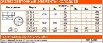
Tables of characteristics, sizes, brands, volumes, weights and prices:
Reinforced Concrete Pipes | |||||||
| Name | Dimensions, mm. | Concrete grade | Volume of concrete, m3 | Weight, tons | Quantity in the car (20t), pcs. | ||
| D | L | t | |||||
| Non-pressure reinforced concrete pipes | |||||||
| TS 40.25-2 | 400 | 2500 | 60 | 300 | 0,24 | 0,541 | 32 |
| TS 40.25-3 | 400 | 2500 | 60 | 300 | 0,24 | 0,541 | 32 |
| TS 40.50-2 | 400 | 5000 | 60 | 300 | 0,38 | 0,95 | 12 |
| TB 50.50 | 500 | 5000 | 60 | 300 | 0,56 | 1,40 | 10 |
| TS 60.25-2 | 600 | 2500 | 65 | 300 | 0,40 | 0,97 | 16 |
| TS 60.25-3 | 600 | 2500 | 65 | 300 | 0,40 | 0,97 | 16 |
| T 60.50-2 | 600 | 5000 | 65 | 300 | 0,66 | 1,65 | 8 |
| TS 80.25-2 | 800 | 2500 | 65 | 300 | 0,76 | 1,767 | 11 |
| TS 80.25-3 | 800 | 2500 | 65 | 300 | 0,76 | 1,767 | 11 |
| TB 80.50 | 800 | 5000 | 65 | 300 | 1,26 | 3,15 | 6 |
| TB 100.50 | 1000 | 5000 | 75 | 300 | 1,95 | 4,88 | 4 |
| TB 120.50 | 1200 | 5000 | 85 | 300 | 2,27 | 5,68 | 4 |
| TS 120.30-2 | 1200 | 3000 | 85 | 300 | 1,70 | 4,158 | 4 |
| TS 120.30-3 | 1200 | 3000 | 85 | 300 | 1,70 | 4,158 | 4 |
| Tfi 140.50-2 | 1400 | 5000 | 90 | 400 | 2,61 | 6,53 | 2 |
| Ts 240.20-4 | 2400 | 2000 | 100 | 400 | 4,82 | 12,05 | 2 |
Vibrohydropressed reinforced concrete pressure pipes | |||||||
| TN-60-II | 600 | 5000 | 65 | 500 | 0,66 | 1,65 | 8 |
| TN-60-III | 600 | 5000 | 65 | 500 | 0,66 | 1,65 | 8 |
| TN-80-II | 800 | 5000 | 65 | 500 | 1,26 | 3,15 | 6 |
| TN-80-III | 800 | 5000 | 65 | 500 | 1,26 | 3,15 | 6 |
| TN-100-II | 1000 | 5000 | 75 | 500 | 1,95 | 4,88 | 4 |
| TN-100-III | 1000 | 5000 | 75 | 500 | 1,95 | 4,88 | 4 |
| TN-120-II | 1200 | 5000 | 85 | 500 | 2,27 | 5,68 | 4 |
| TN-120-III | 1200 | 5000 | 85 | 500 | 2,27 | 5,68 | 4 |
CONTROL AND TEST METHODS
5.1. Pipe strength testing
5.1.1. Pipe strength control should be carried out by loading in accordance with GOST 8829-77.
5.1.2. Pipe strength tests are carried out at positive air temperatures and the tested pipe after the concrete reaches the design grade for axial tensile strength.
5.1.3. A whole pipe or a section of pipe with a length of at least 1 m is subjected to a load test. It is allowed to use pipes that have passed hydrostatic tests for water tightness for the load test.
5.1.4. Schemes for supporting and loading pipes when testing them for strength are shown in Fig. 6 and 7, and the values of the control loads are in table. 6 of this standard.
5.1.5. Pipe strength tests are carried out in the following order.
The pipe is installed horizontally on two wooden blocks laid parallel on a rigid base.
Socket pipe test diagram
1
- rubber gasket or cement mortar;
2
- wooden blocks;
3
- steel cross beam
Seam pipe test diagram
1
- rubber gasket or cement mortar:
2
- wooden blocks;
3
- steel cross beam
A wooden block is installed on the pipe along the upper cylindrical part forming it, and a steel cross-beam is placed on it.
Wooden blocks must have the dimensions indicated in the table. 9 .
The rigidity of the steel traverse must be such that the deflection of the traverse under maximum load does not exceed 1/720 of its length.
In order to uniformly transfer the load to the pipe, a leveling layer of cement mortar or a strip of sheet rubber 20-30 mm thick is laid under the upper and lower bars. Sheet rubber should have a Shore hardness ranging from 45 to 60.
ACCEPTANCE RULES
4.1. Acceptance of pipes should be carried out in batches in accordance with the requirements of GOST 13015.1-81 and this standard, depending on the specifics of a particular production.
4.2. Tests of concrete pipes should be carried out at least: for water resistance - once every three months, for frost resistance, as well as water absorption (in the cases provided for in clause 2.6.6 of this standard) - once every six months.
4.3. Testing of pipes for water resistance should be carried out at least once every two weeks by testing two pipes (for pipes of the highest quality category - four pipes) from the following number of manufactured pipes: 1000 pcs. — diameter 100-200 mm; 500 pcs. — diameter 300-600 mm; 200 pcs. — with a diameter of 800, 1000 mm.
Pipes are considered to have passed the water tightness test if, after exposing them to water under pressure in accordance with clause 5.2.2. Water leakage in the form of individual drops or leaks will not be detected on the outer surface of the pipe.
The appearance of damp spots on the outer surface of a pipe being tested for water tightness cannot serve as a basis for rejecting the pipe.
In case of unsatisfactory results of testing pipes for water resistance, tests are carried out on twice the number of pipes that were not tested.
If, during re-inspection, at least one pipe does not meet the requirements of this standard, then the pipes should be accepted individually.
4.4. Acceptance of pipes by strength
4.4.1. Strength testing of pipes should be carried out at least once every two weeks by loading two pipes from the following number of pipes being manufactured: 1000 pcs. — diameter 100-200 mm; 500 pcs. — diameter 300-600 mm; 200 pcs. — with a diameter of 800, 1000 mm.
4.4.2. Pipe strength assessment - according to GOST 8829-77. In this case, the control load should be taken according to the table. 6 of this standard.
4.4.3. If pipes of group 2 in terms of load-bearing capacity, according to the results of strength tests, do not meet the requirements given in table. 6, then they are tested according to the indicators of the 1st group in terms of load-bearing capacity.
The use of pipes that, based on test results, did not meet the strength requirements established for products of the first group - in accordance with GOST 8829-77.
Pipes transferred from one group to another based on test results are not subject to certification in the highest quality category.
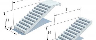
Pipe links as a central element of the design of culverts
In the process of laying railway tracks and highways, it often becomes necessary to pass a small body of water under the embankment - a stream or even a river. To achieve such goals, specially designed culvert structures are used, which consist of links of reinforced concrete pipes and structures. The process of assembling such structures is carried out even before the foundation is poured for the roadway.
Purpose:
In many regions of the Russian Federation, in the process of filling the ballast prism of railway tracks or roads, it is necessary to install culverts that would contribute to the preservation of the country’s natural reservoirs. And in this case, it is extremely important that the resulting directed water flow does not have a negative impact on the embankment under the road.
The design of culverts consists of:
- reinforced concrete pipe links;
- heads, which in turn also consist of a number of elements. First of all, these are foundation blocks and slabs, as well as walls, which form the basis of a U-shaped portal that helps protect the embankment from erosion and other negative influences of various factors.
The diameter of the links primarily depends on the power of the water flow.
Sequence of assembly of the structure
The process of collecting culverts is carried out even before the foundation is poured for the roadway, but after the natural water flow is diverted away from the place where the main work will be carried out. At this stage, it is important to follow a certain sequence of actions:
- Formation of a pit;
- Preparation device for structures;
- The process of collecting a culvert structure;
- Carrying out waterproofing work;
- Completion of work.
At the same time, stage 3 is recognized as one of the most important stages, and in particular, the installation of structural seams.
The process of making these seams consists of two stages:
- from the outside, 2 bundles of tow are driven into them
- after that, the sinuses formed between the bundles and the surface of the pipe are sealed both outside and inside.
The process of connecting pipe sections requires careful monitoring by engineers and technicians, since incorrect work can lead to serious problems in the future.
Rectangular pipe links
| Name | Dimensions, mm. | Quantity in the car (20t), pcs. | ||
| L | B | H | ||
| 3P 8.100 | 1000 | 1740 | 2400 | 6 |
| 3P 11.100 | 1000 | 2260 | 2500 | 4 |
| 3P 12.100 | 1000 | 2320 | 2680 | 3 |
| 3P 17.100 | 1000 | 3400 | 3140 | 2 |
| 3P 18.100 | 1000 | 3460 | 3320 | 2 |
| 3P 19.100 | 1000 | 4360 | 3060 | 2 |
| 3P 20.100 | 1000 | 4429 | 3100 | 2 |
| 3P 21.100 | 1000 | 4600 | 3300 | 1 |
| 3P 21.75 | 750 | 4600 | 3300 | 1 |
Pipe heads
| Name | Dimensions, mm. | Quantity in the car (20t), pcs. | ||
| L | B | H | ||
| OP-6 (d=900mm) | 6000 | 300 | 2000 | 4 |
| OP-8 (d=1250mm) | 6000 | 300 | 2000 | 5 |
| OP-10 (d=1540mm) | 6000 | 300 | 2000 | 5 |
| OP-8A (d=1000/1250mm) | 6000 | 300 | 2000 | 5 |
| OP-10A (d=1200/1540mm) | 6000 | 300 | 2000 | 5 |
Round links
| Name | Dimensions, mm. | Quantity in the car (20t), pcs. | ||
| L | D | t | ||
| 3K 4.100 | 1000 | 1000 | 120 | 16 |
| 3K 5.100 | 1000 | 1250 | 120 | 14 |
| 3K 9.100 | 1000 | 1500 | 160 | 7 |
| 3K 10.100 | 1000 | 1500 | 220 | 7 |
| 3K 9.100 l/a | 1000 | 1500 | 160 | 7 |
Round links with flat base for laying
| Name | Dimensions, mm. | Quantity in the car (20t), pcs. | ||
| L | D | b | ||
| 3KP 2.150 | 1500 | 1000 | 120 | 10 |
| 3KP 6.150 | 1500 | 1500 | 160 | 6 |
| 3KP 15.150 | 1500 | 1000 | 100 | 10 |
| 3KP 17.150 | 1500 | 1500 | 140 | 4 |
Without any exaggeration, it can be said that the condition of roads in Russia today is in a crisis. Thus, the length of those road sections that do not meet the established standards for transport and operational condition is more than 76% of the total length of roads in the Russian Federation. It is also worth noting that roads are decommissioned 2 times more often than new ones are introduced.
The percentage of federal roads that operate under constant overload is also increasing - today there are up to 28.8% of the total number of such roads. Such a deviation from the road load standards also leads to an increase in road transportation costs (by at least 20-30%). This situation is absolutely unacceptable, especially taking into account the fact that most international transport is also carried out along federal road networks.
The only solution applicable in such a situation is the reconstruction and modernization of those roads that are already practically worn out, with their subsequent expansion and increase in the number of lanes. However, the problem is that the traditional construction technologies used today do not provide the opportunity to quickly reconstruct even the most problematic roads, since the execution of work directly depends on weather conditions.
That is why road construction in Russia is seasonal work that cannot be accelerated. At the same time, the duration of warm periods is extremely short, especially in some regions of the country, which further reduces the possibility of rapid reconstruction of problem roads.
However, seasonality of work is not the only problem inherent in modern construction and reconstruction technologies (Fig. 1). For example, in order to increase the width of the roadway, it is necessary to organize 1- or 2-sided widening of earthen embankments. At the same time, there is a high probability that there will be a need for subsequent reconstruction of the drainage system; in addition, embankments may collapse due to an incorrect technological approach.
There is no doubt that in order to solve the problem of increased congestion and wear and tear of roads in Russia, it is necessary to use completely different construction and modernization technologies, as well as to use new modern building materials. In this regard, the authors of this article propose to study an alternative approach to the reconstruction of highways, which consists in the use of specially manufactured prefabricated reinforced concrete elements. And the essence of the alternative construction option is the additional installation of half-bridges on both sides of the existing embankment, which will be made of reinforced concrete structures (Fig. 2).
The construction of these half-bridges requires the use of the following “road” structures: beams, slabs and posts. Road slabs should be laid on beams, which should already be in a perpendicular position relative to the road axis. In this case, monolithic reinforced concrete bored piles serve as support for one end of the beam, and road racks for the other end. It should also be taken into account that the beams can have different lengths, depending on how many lanes are needed for a particular road.
The authors of the article propose to carry out the reconstruction of roads using the in-line method, while still implementing some types of work based on the time of year and the properties of the materials used in a particular case. For example, the installation of bored reinforced concrete piles should be carried out exclusively during the warm period, because the concrete mixture becomes strong only at temperatures above 0 degrees. And the installation of prefabricated reinforced concrete structures, on the contrary, is absolutely not tied to temperature indicators and can be carried out without problems even in winter.
Therefore, with proper distribution of all work throughout the year, the necessary uniformity of the work process can be achieved, which ultimately will reduce the time required for the reconstruction of highways by several times. It will also be possible to carry out several types of work at the same time, if safety regulations allow this.
The conducted research, based on the use of prefabricated reinforced concrete structures, acts as a continuation of research related to the development of methods for constructing overpass-type roads from prefabricated reinforced concrete structures [1, 2]. In the case of practical application of the results of these studies, a new impetus may arise that is necessary for the modern construction of highways in Russia, since the described technology makes it possible to make maximum use of the country’s currently available industrial potential.
Pipe diaphragms
| Name | Dimensions, mm. | Quantity in the car (20t), pcs. | ||
| L | B | H | ||
| DP-12 (d=1460/1780mm) | 2400 | 250 | 2700 | 7 |
| DP-14 (d=1760/2080mm) | 2400 | 300 | 2900 | 5 |
Pipe flaps
| Name | Dimensions, mm. | Quantity in the car (20t), pcs. | ||
| L | B | H | ||
| OG-18 | 3000 | 1100 | 1800 | 7 |
| OG-33 | 2000 | 1600 | 3300 | 4 |
| OG-28 | 2000 | 1400 | 2800 | 5 |
Diaphragm heads
| Name | Dimensions, mm. | Quantity in the car (20t), pcs. | ||
| L | B | H | ||
| DR-8 (d=1000mm) | 1800 | 350 | 2200 | 9 |
| DR-10 (d=1240mm) | 1800 | 350 | 2700 | 8 |
| DR-12 (d=1460mm) | 2400 | 350 | 2700 | 6 |
| DR-14 (d=1760mm) | 2400 | 400 | 3300 | 5 |
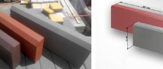
Sloping walls
| Name | Dimensions, mm. | Quantity in the car (20t), pcs. | ||
| L | B | H | ||
| ST-1 | 3610 | 300 | 1890 | 5 |
| ST-2 | 4150 | 300 | 2770 | 3 |
| Name | Dimensions, mm. | Quantity in the car (20t), pcs. | ||
| L | B | H | ||
| ST-3 | 2790 | 300 | 1750 | 7 |
| ST-4 | 2270 | 300 | 1850 | 8 |
| ST-5 | 2470 | 300 | 2200 | 6 |
| ST-6 | 2790 | 300 | 2700 | 5 |