The rapid development of the oil production and processing complex and the agricultural sector of the economy requires reliable storage places for raw materials. A reinforced concrete tank is a universal object that is equally suitable for oil and potassium-nitrogen mixture, which has become popular among agricultural enterprises. Standard projects allow you to choose your own concrete product for each case.
Disadvantages and alternatives in modern construction
What are the disadvantages of using reinforced concrete tanks?
In the Russian Federation, like other countries of the post-Soviet space, water supplies for drinking or household purposes are often stored in reinforced concrete tanks. The recommendations given in the regulatory framework for the use of reinforced concrete in structures played a major role in their spread. In addition, the cost of constructing tanks made of reinforced concrete remains very attractive to this day. But many people do not know that with the initially lower price of reinforced concrete tanks, their further operation is accompanied by high costs for inspection, maintenance, repair of leaks, and repairs. Moreover, often these costs are not just comparable to the price of the tank, but even exceed it many times.
All tanks made of reinforced concrete have a common design drawback - there is a bund around them, the presence of which does not allow for a normal inspection of the tanks, assessing the condition of their walls and the connections of the panels that make them up. If defects are detected, embankment makes it difficult to carry out repair work and increases their cost. Data based on experience in operating reinforced concrete tanks indicate that these are defects through which the stored liquid leaks.
Reinforced concrete tanks for storing drinking water are structures made of monolithic reinforced concrete about 5 m deep. Precast reinforced concrete columns serve as supports for a beamless flat floor. Inside, reinforced concrete partitions divide the tank into separate sections. In practice, it is customary to completely or partially bury reinforced concrete tanks into the ground, protecting them from above from freezing with a 1-meter layer of soil.
Most often, drinking water tanks and settling tanks of water supply stations need inspection. Getting groundwater into reservoirs is prohibited due to sanitary standards. If water from the tank leaks into the ground, it will damage its foundation.
If scheduled surveys and inspections of reinforced concrete tanks are carried out untimely and of poor quality, the risk of expansion of existing defects and the formation of new ones will increase, especially in places inaccessible to simple visual inspection. Inattentiveness or lack of competence of specialists conducting examinations and inspections leads to ignoring such areas. Over time, damage increases in size, leakage of stored liquid increases, negatively affecting the surrounding ecology and technological processes. During operation, tank structures made of reinforced concrete are influenced by clean water, and during cleaning - by chemicals (sodium hypochlorite, chlorine, etc.). Parts of the structure located above the water level are destroyed under the influence of carbon dioxide contained in the air.
Based on the concentration of chlorides and sulfates, as well as the pH value, the level of influence of water on concrete and reinforced concrete structures in drinking water tanks and settling tanks is considered non-aggressive. But, nevertheless, drinking water has an impact on reinforced concrete structures. It manifests itself in the form of certain processes:
- the interaction of carbon dioxide dissolved in water with calcium hydroxide, which is part of the cement, leads to the formation of calcium bicarbonate, soluble in water;
- water leaches calcium hydroxide from the cement composition, which leads to a decrease in the density of concrete in the surface layers;
- concrete is carbonized by carbon dioxide in the air to form calcium carbonate. Under favorable conditions, it can accumulate in the pores and cracks of concrete, tearing it apart from the inside. According to the information obtained during the research, the carbonization of concrete in settling tanks is very deep. Over the course of 20-30 years, this process reaches not just the reinforcement, but covers the entire mass of concrete along its entire thickness.
- chlorine interacts with calcium hydroaluminates, hydrosilicates, hydroxide and other alkaline components of cement. As a result, the cement stone dissolves in the surface layer of concrete. If the percentage of chlorides exceeds 0.5% by weight of cement, corrosion of the reinforcement begins.
The internal surfaces of tanks that have been in use for 20 years or more must be covered with a protective layer of shotcrete. As surveys show, during this time there is a thorough destruction of the shotcrete and a softening of the concrete layer located behind it. If the protective layer is of sufficient thickness (15-20 mm), then there is no corrosion on the steel reinforcement. If you reduce the thickness of the protective layer by 5 mm, the corrosion process begins. To fix it, you will need to remove the remaining shotcrete and apply a protective layer to the load-bearing part of the tank.
The strongest destructive effect on the structures of drinking water tanks and settling tanks made of reinforced concrete is through the filtration of liquid through cracks in the coatings, walls and bottom. Such cracks can appear as a result of general deformation of the tank caused by uneven settlement of the soil, or deformation of individual reinforced concrete elements caused by temperature changes. A decrease in the pH of concrete in the crack zone and the simultaneous supply of dissolved oxygen contribute to the formation of a galvanic couple on the surface of the reinforcement (the anode is located in the crack). The steel in the crack dissolves. If corrosion is sufficiently intense, reinforcement may break at cracks.
Restoration and repair work in drinking water reservoirs and settling tanks involves restoring the protective layer of concrete, using materials to protect reinforced concrete structures from the leaching effect of water, sealing cracks by using seam waterproofing compounds, and restoring the cross-section of steel reinforcement.
As a result, it turns out that the initially small price of installing a reinforced concrete tank results in significant costs for its operation and maintaining the appropriate condition.
What alternatives are there?
One of the most practical and widely used options in Europe is a prefabricated steel tank. Its main advantages are:
- corrosion resistance
- excellent sealing properties
- hygiene
- no need for painting
- easy assembly and quick dismantling
- Possibility of installation in technically difficult conditions
- possibility of increasing volume
Initially, the cost of such a tank is higher than the cost of a reinforced concrete one. But when you take into account all the additional costs - from installation to maintenance - a significant benefit is revealed.
Find out more about prefabricated steel tanks >>
Reinforced concrete monolithic fire tank
- Content:
- Structural elements of concrete tanks
- Installation of monolithic concrete tanks
- Sectoral system for the construction of concrete tanks
- Concrete ring tanks
- Rectangular tanks
- Protecting tanks from freezing
Fire tanks are a very important part of the fire safety system. They must ensure that adequate quantities of water are stored and available at all times. Regardless of the time of year, water must be protected from evaporation and freezing. In large industrial facilities, residential complexes or public buildings, the most practical and compliant with all fire safety requirements are monolithic concrete fire tanks.
Structural elements of concrete tanks
A monolithic fire tank for storing fire water has a cylindrical or rectangular shape. Each fire-type tank must have the following required parts:
- power supply pipes
- drain pipe
- overfill protection system
- fill level control system
- submersible pumps
- hatch for fire hoses
The walls and floor of the tank are monolithic concrete products reinforced with steel reinforcement. The outer part of the walls is covered with a layer of thermal insulation, which should protect the contents of the container from freezing.
The upper part of the reservoir ceiling is equipped with one or two hatches, which are used for immersing fire hoses in the event of a non-working condition of submersible pumps. Often tanks are equipped with pipes with fire connectors of a standard diameter, allowing direct connection of fire hoses using couplings.
The overflow system consists of a pipe at the top of the tank connected to the drain pipe and connected to the storm drain. If the tank overflows and the tank filling control system does not work in time, water flows through the pipe and drains into the sewer, eliminating flooding of the above-ground part of the tank or the ground surface.
Installation of monolithic concrete tanks
Monolithic concrete fire tanks used in industrial facilities have been built for many decades. Previous standards required the construction of cylindrical containers, completely or partially buried in the ground. Installation of a large-volume cylindrical monolithic tank is a difficult technological task that requires solving complex construction problems.
Such tanks are justified for large volumes of stored water - stresses from liquid pressure are distributed evenly and the walls of the structure are not subject to cracking. Later reinforced concrete fire-fighting monolithic tanks were built using a complex pattern of sectoral pouring of concrete.
Sectoral system for the construction of concrete tanks
The peculiarities of this technology are that after filling the bottom with a monolithic layer of concrete, the walls are reinforced with a steel frame to the full height. Then the frame is divided by formwork into separate sectors for the entire height, forming longitudinal strips isolated from each other. Through one, these cavities are filled with Portland cement concrete. After the concrete hardens, the remaining volume is filled, but with stressed cement mortar.
Expanding, this concrete compresses the already hardened strips, and monolithic fire tanks are completely sealed. The seams of the joints are compressed with very great force and become impervious to water under the design pressure. This construction method is quite complex and is characterized by high costs. But the tanks turn out to be very reliable and have an extremely long service life.
Concrete ring tanks
A simpler option for constructing fire tanks from reinforced concrete using concrete elements in the form of rings of a given diameter. This is a very technologically advanced method, characterized by speed of installation. The only difficulty is the stage of sealing the joints between the elements, especially in the area where the walls and bottom meet.
Waterproofing is carried out using cement-polymer mixtures, which are pumped under pressure into the joints, followed by coating with special compounds, for example “KTtron-10 2K”. The same composition is used to insulate the junctions of pipes, pipes and other technological elements.
Rectangular tanks
Modern fire safety rules and regulations allow the construction of rectangular fire reservoirs. This not only greatly simplifies the technological process, but also significantly reduces the cost of the design.
The use of high-quality concrete compositions with the addition of plasticizers and polymer additives allows us to obtain surfaces of very high strength that can withstand water pressure at any level without deformation or cracking.
Protecting tanks from freezing
Concrete tanks are installed in various designs:
- above ground
- partially buried
- underground
The thermal conductivity of concrete does not allow it to be considered a reliable heat insulator. In frosty winters, the cold penetrates even thick walls and threatens to freeze the water. This can lead not only to the unsuitability of the reservoir for fire purposes, but also to the destruction of the entire structure.
In addition to thermal insulation with polystyrene foam, internal heating devices made of stainless steel are very often used. These are ordinary radiators or systems of surrounding pipelines through which hot water is pumped during the cold season. The heat capacity of water is very large, so even a single heating of the entire volume of liquid provides protection against freezing for quite a long time.
Among all modifications of fire tanks, monolithic reinforced concrete fire tanks have the longest service life and the lowest operating costs.
Reinforced concrete tank - types and use of storage facilities for water and petroleum products
The rapid development of the oil production and processing complex and the agricultural sector of the economy requires reliable storage places for raw materials. A reinforced concrete tank is a universal object that is equally suitable for oil and potassium-nitrogen mixture, which has become popular among agricultural enterprises. Standard projects allow you to choose your own concrete product for each case.
Standard designs for RVS tanks
1. Standard design TP 704-1-249с.92 Vertical cylindrical steel tank for storing fuel oil with a capacity of 100 m3 (full version)
- TP 704-1-249 p.92. Album 1. Explanatory note. Technological, electrical, automation equipment.
- TP 704-1-249 p.92. Album 2. Metal structures.
- TP 704-1-249 p.92. Album 3. Foundations and foundations.
- TP 704-1-249 p.92. Album 4. Thermal insulation.
- TP 704-1-249 p.92. Album 5. Basic provisions for the installation of thermal insulation structures.
- TP 704-1-249 p.92. Album 6. Basic provisions for the installation of metal structures.
- TP 704-1-249 p.92. Album 7. Equipment specifications.
- TP 704-1-249 p.92. Album 8. Statements of material requirements.pdf
- TP 704-1-249 p.92. Album 9. Estimates.
Calculate the cost of a vertical steel tank 100 m3 Completed projects
2. Standard design TP 704-1-250 p.92. Vertical cylindrical steel tank for storing fuel oil with a capacity of 200 m3 (full version)
- TP 704-1-250 p.92. Album 1. Explanatory note. Technological, electrical, automation equipment.
- TP 704-1-250 p.92. Album 2. Metal structures.
- TP 704-1-250 p.92. Album 3. Foundations and foundations.
- TP 704-1-250 p.92. Album 4. Thermal insulation.
- TP 704-1-250 p.92. Album 5. Basic provisions for the installation of thermal insulation structures.
- TP 704-1-250 p.92. Album 6. Basic provisions for the installation of metal structures.
- TP 704-1-250 p.92. Album 7. Equipment specification.
- TP 704-1-250 p.92. Album 8. List of materials requirements.
- TP 704-1-250 p.92. Album 9. Estimates.
Calculate the cost of a vertical steel tank 200 m3 Completed projects
3. Standard design TP 704-1-251 p.92. Vertical cylindrical steel tank for storing fuel oil with a capacity of 300 m3 (full version)
- TP 704-1-251 p.92. Album 1. Explanatory note. Technological, electrical, automation equipment.
- TP 704-1-251 p.92. Album 2. Metal structures.
- TP 704-1-251 p.92. Album 3. Foundations and foundations.
- TP 704-1-251 p.92. Album 4. Thermal insulation.
- TP 704-1-251 p.92. Album 5. Basic provisions for the installation of thermal insulation structures.
- TP 704-1-251 p.92. Album 6. Basic provisions for the installation of metal structures.
- TP 704-1-251 p.92. Album 7. Equipment specification.
- TP 704-1-251 p.92. Album 8. List of materials requirements.
- TP 704-1-251 p.92. Album 9. Estimates.
Calculate the cost of a vertical steel tank 300 m3 Completed projects
4. Standard design TP 704-1-51. Steel vertical cylindrical tank for oil and petroleum products with a capacity of 300 m3 (full version)
- TP 704-1-51. Album 1. Working drawings of the KM tank.
- TP 704-1-51. Album 2. Working drawings of the KM pontoon.
- TP 704-1-51. Album 3. Foundations and foundations.
- TP 704-1-51. Album 4. Equipment of a tank with a pontoon for gasoline.
- TP 704-1-51. Album 5. Equipment of a tank for light petroleum products.
- TP 704-1-51. Album 6. Equipment of a tank for dark oil products.
- TP 704-1-51. Album 7. Estimates.
Calculate the cost of a vertical steel tank 300 m3 Completed projects
5. Standard design TP 704-1-252с.92. Vertical cylindrical steel tank for storing fuel oil with a capacity of 400 m3 (full version)
- TP 704-1-252s.92. Album 1. Explanatory note. Technological, electrical, automation equipment.
- TP 704-1-252s.92. Album 2. Metal structures.
- TP 704-1-252s.92. Album 3. Foundations and foundations.
- TP 704-1-252s.92. Album 4. Thermal insulation.
- TP 704-1-252s.92. Album 5. Basic provisions for the installation of thermal insulation structures.
- TP 704-1-252s.92. Album 6. Basic provisions for the installation of metal structures.
- TP 704-1-252s.92. Album 7. Equipment specification.
- TP 704-1-252s.92. Album 8. List of materials requirements.
- TP 704-1-252s.92. Album 9. Estimates.
Calculate the cost of a vertical steel tank 400 m3 Completed projects
6. Standard design TP 704-1-52. Steel vertical cylindrical tank for oil and petroleum products with a capacity of 400 m3 (full version)
- TP 704-1-52. Album 1. Working drawings of the KM tank.
- TP 704-1-52. Album 2. Working drawings of the KM pontoon.
- TP 704-1-52. Album 3. Foundation and foundations.
- TP 704-1-52. Album 4. Equipment of a tank with a pontoon for gasoline.
- TP 704-1-52. Album 5. Equipment of a tank for light petroleum products.
- TP 704-1-52. Album 6. Equipment of a tank for dark oil products.
- TP 704-1-52. Album 7. Estimates.
Calculate the cost of a vertical steel tank 400 m3 Completed projects
7. Standard design TP 704-1-253с.92. Vertical cylindrical steel tank for storing fuel oil with a capacity of 500 m3 (full version)
- TP 704-1-253s.92. Album 1. Explanatory note. Technological, electrical, automation equipment.
- TP 704-1-253s.92. Album 2. Metal structures.
- TP 704-1-253s.92. Album 3. Foundations and foundations.
- TP 704-1-253s.92. Album 4. Thermal insulation.
- TP 704-1-253s.92. Album 5. Basic provisions for the installation of thermal insulation structures.
- TP 704-1-253s.92. Album 6. Basic provisions for the installation of metal structures.
- TP 704-1-253s.92. Album 7. Equipment specification.
- TP 704-1-253s.92. Album 8. List of materials requirements.
- TP 704-1-253s.92. Album 9. Estimates.
Calculate the cost of a vertical steel tank 500 m3 Completed projects
8. Standard design TP 704-1-254с.92. Vertical cylindrical steel tank for storing fuel oil with a capacity of 700 m3 (full version)
- TP 704-1-254с.92. Album 1. Explanatory note. Technological, electrical, automation equipment.
- TP 704-1-254с.92. Album 2. Metal structures.
- TP 704-1-254с.92. Album 3. Foundations and foundations.
- TP 704-1-254с.92. Album 4. Thermal insulation.
- TP 704-1-254с.92. Album 5. Basic provisions for the installation of thermal insulation structures.
- TP 704-1-254с.92. Album 6. Basic provisions for the installation of metal structures.
- TP 704-1-254с.92. Album 7. Equipment specification.
- TP 704-1-254с.92. Album 8. List of materials requirements.
- TP 704-1-254с.92. Album 9. Estimates.
Calculate the cost of a vertical steel tank 700 m3 Completed projects
9. Standard design TP 704-1-255с.92. Vertical cylindrical steel tank for storing fuel oil with a capacity of 1000 m3 (full version)
- TP 704-1-255s.92. Album 1. Explanatory note. Technological, electrical, automation equipment.
- TP 704-1-255s.92. Album 2. Metal structures.
- TP 704-1-255s.92. Album 3. Foundations and foundations.
- TP 704-1-255s.92. Album 4. Thermal insulation.
- TP 704-1-255s.92. Album 5. Basic provisions for the installation of thermal insulation structures.
- TP 704-1-255s.92. Album 6. Basic provisions for the installation of metal structures.
- TP 704-1-255s.92. Album 7. Equipment specification.
- TP 704-1-255s.92. Album 8. List of materials requirements.
- TP 704-1-255s.92. Album 9. Estimates.
Calculate the cost of a vertical steel tank 1000 m3 Completed projects
10. Standard design TP 704-1-166.84. Vertical cylindrical steel tank for oil and petroleum products with a capacity of 1000 m3 (full version)
- TP 704-1-166.84. Album 1. Metal tank structures.
- TP 704-1-166.84. Album 2. Metal pontoon structures.
- TP 704-1-166.84. Album 3. Foundation and foundations. Fastening units.
- TP 704-1-166.84. Album 4. Equipment of a tank with a pontoon for oil and petroleum products.
- TP 704-1-166.84. Album 5. Equipment of a tank without a pontoon for oil and petroleum products.
- TP 704-1-166.84. Album 6. Equipment of tanks without pontoons for highly solidified oils and oil products.
- TP 704-1-166.84. Album 7. Project for installation works. Tank installation.
- TP 704-1-166.84. Album 8. Project for installation works. Installation accessories.
- TP 704-1-166.84. Album 9. Custom specifications.
- TP 704-1-166.84. Album 10. Estimates.
Calculate the cost of a vertical steel tank 1000 m3 Completed projects
11. Standard design TP 704-1-167.84. Vertical cylindrical steel tank for oil and petroleum products 2000 m3 (full version)
- TP 704-1-167.84. Album 1. Metal tank structures.
- TP 704-1-167.84. Album 2. Metal pontoon structures.
- TP 704-1-167.84. Album 3. Foundation and foundations. Fastening units.
- TP 704-1-167.84. Album 4. Equipment of a tank with a pontoon for oil and petroleum products.
- TP 704-1-167.84. Album 5. Equipment of a tank without a pontoon for oil and petroleum products.
- TP 704-1-167.84. Album 6. Equipment of tanks without pontoons for highly solidified oils and oil products.
- TP 704-1-167.84. Album 7. Project for installation works. Tank installation.
- TP 704-1-167.84. Album 8. Project for installation works. Installation accessories.
- TP 704-1-167.84. Album 9. Custom specifications.
- TP 704-1-167.84. Album 10. Estimates.
- TP 704-1-167.84. Album 11. Statements of material requirements.
Calculate the cost of a vertical steel tank 2000 m3 Completed projects
12. Standard design TP 704-1-168.84. Vertical cylindrical steel tank for oil and petroleum products 3000 m3 (full version)
- TP 704-1-168.84. Album 1. Metal tank structures.
- TP 704-1-168.84. Album 2. Metal pontoon structures.
- TP 704-1-168.84. Album 3. Foundation and foundations. Fastening units.
- TP 704-1-168.84. Album 4. Equipment of a tank with a pontoon for oil and petroleum products.
- TP 704-1-168.84. Album 5. Equipment of a tank without a pontoon for oil and petroleum products.
- TP 704-1-168.84. Album 6. Equipment of tanks without pontoons for highly solidified oils and oil products.
- TP 704-1-168.84. Album 7. Project for installation works. Tank installation.
- TP 704-1-168.84. Album 8. Project for installation works. Installation accessories.
- TP 704-1-168.84. Album 9. Custom specifications.
- TP 704-1-168.84. Album 10.87 Estimates.
- TP 704-1-168.84. Album 11. Statements of material requirements.
Calculate the cost of a vertical steel tank 3000 m3 Completed projects
13. Standard design TP 704-1-169.84. Vertical cylindrical steel tank for oil and petroleum products 5000 m3 (full version)
- TP 704-1-169.84. Album 1. Metal tank structures.
- TP 704-1-169.84. Album 2. Metal pontoon structures.
- TP 704-1-169.84. Album 3. Foundation and foundations. Fastening units.
- TP 704-1-169.84. Album 4. Equipment of a tank with a pontoon for oil and petroleum products.
- TP 704-1-169.84. Album 5. Equipment of a tank without a pontoon for oil and petroleum products.
- TP 704-1-169.84. Album 6. Equipment of tanks without pontoons for highly solidified oils and oil products.
- TP 704-1-169.84. Album 7. Project for installation works. Tank installation.
- TP 704-1-169.84. Album 8. Project for installation works. Installation accessories.
- TP 704-1-169.84. Album 9. Custom specifications.
- TP 704-1-169.84. Album 10 Estimates.
- TP 704-1-169.84. Album 11. Statements of material requirements.
Calculate the cost of a vertical steel tank 5000 m3 Completed projects
14. Standard design TP 704-1-170.84. Vertical cylindrical steel tank for oil and petroleum products 10000 m3 (full version)
- TP 704-1-170.84. Album 1. Metal tank structures.
- TP 704-1-170.84. Album 2. Metal pontoon structures.
- TP 704-1-170.84. Album 3. Foundation and foundations. Fastening units.
- TP 704-1-170.84. Album 4. Equipment of a tank with a pontoon for oil and petroleum products.
- TP 704-1-170.84. Album 5. Equipment of a tank without a pontoon for oil and petroleum products.
- TP 704-1-170.84. Album 6. Equipment of tanks without pontoons for highly solidified oils and oil products.
- TP 704-1-170.84. Album 7. Project for installation works. Tank installation.
- TP 704-1-170.84. Album 8. Project for installation works. Installation accessories.
- TP 704-1-170.84. Album 9. Custom specifications.
- TP 704-1-170.84. Album 10 Estimates.
Calculate the cost of a vertical steel tank 10,000 m3 Completed projects
Reinforced concrete tanks
The development of the oil industry, agriculture and manufacturing does not stand still, which means that tanks for storing liquid production products are constantly required. There are many types of such containers, the most common of which are those made of reinforced concrete. Their shapes and types are very diverse, which makes them more widely used every day.
Types of containers
A set of structures made of reinforced concrete that allows the storage of process fluids is concrete tanks. Due to their relatively low cost and long service life, they are also used in housing and communal services. The low thermal conductivity of the container prevents the rapid evaporation of liquid products.
Concrete containers - common types of objects
| The principle of separation | View | Characteristic |
| Preparation method | Monolithic | The design of the facility is carried out at the site of future operation by pouring concrete |
| Prefabricated | Built from individual blocks | |
| Mixed type | Assembled from large elements connected from prefabricated blocks using heavy-duty concrete | |
| Form | Rectangular | Made in the shape of a rectangle |
| Cylindrical | Produced in the form of a cylinder | |
| Location | Overhead | The main structure is above the ground |
| Underground | Designed for underground use |
Definition. Purpose
Reinforced concrete tanks are containers for storing liquids that consist of structural elements made of reinforced concrete. They are one of the most common storage facilities used in manufacturing, industry, agriculture and water supply. This is due to their relatively low cost and durability. Most often they store water or oil. These tanks have low thermal conductivity, so liquid products stored in them evaporate less than, say, in metal ones.
Advantages and disadvantages
The advantages of such tanks:
- low thermal conductivity;
- less flammable than metal ones;
- more resistant to corrosion.
- The need to make an embankment around the structure. This does not allow detailed verification of the integrity of the reinforced concrete tank. If a design defect is discovered, it prevents the defects from being corrected.
- High costs for their operation. According to standard operating instructions, to carry out repairs, an additional protective layer of concrete with waterproof admixtures is made.
- High price.
- If they are in groundwater, then there is a great danger of their surfacing.
- Long installation.
Return to contents
Classification of tanks by type of production:
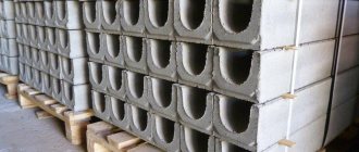
Prefabricated reinforced concrete tanks consist of parts and are folded using special equipment. At the junction of structures, they resort to special mixtures and solutions that have water-repellent properties. Sealing seams with ring reinforcement using winding equipment is not necessary and is rarely used. In this case, the seams are also sealed with additional mortar (fill thickness 10-15 cm). An air-entraining agent is added to the solution to increase water resistance. Prefabricated-monolithic - structures that consist of separate, previously manufactured parts of reinforced concrete, monolithic into a single structure at the joint. High-strength concrete is used for connections.
Types by shape:
Classification by location:
Containers vary in shape and volume. Reinforced concrete is the most suitable material for storing liquids, so it is used for the manufacture of containers for water intakes and fire-fighting reservoirs. Monolithic ones are made predominantly rectangular and placed and constructed underground: formwork is made - reinforced - a waterproof concrete solution is rolled in - waterproofing is laid out in the tank - a roof is installed using reinforced concrete slabs.
Advantages and disadvantages
A small project budget and long-term operation are the main advantages of choosing tanks.
Positive properties of concrete tanks:
- Simplification of installation work. The versatility of reinforced concrete material has ensured its widespread use, which has led to improved construction of facilities.
- High manufacturability of concrete. Technical characteristics allow you to build structures of various shapes and options for their use.
- Low cost. Makes it possible to carry out construction with low-budget financing.
- Fire safety. Used for storing fire extinguishing liquids.
- Neutrality to aggressive environment. This property allows the tanks to be used in wastewater treatment plants.
- Resistance to dynamic and static deformations. Calculation of the impact of loads on the structure determined that such facilities are used in regions with a risk of earthquakes.
Negative qualities of concrete tanks:
- Requires the construction of a protective earthen rampart. If liquid leaks, the embankment will have to be destroyed to carry out repair work.
- Increased operating costs. During major repairs, a special layer is constructed to protect against moisture.
- Difficult installation. Construction requires a lot of labor time.
- Danger of floating. When operating on soils with high water content, there is a risk of deformation of the structure from hydraulic influence.
Protection of reinforced concrete tanks
The reinforced concrete water tank has technical and operational requirements. Standard rules for the operation of reinforced concrete tanks and sanitary standards provide all the necessary requirements for their use. Sanitary standards requirements for reservoirs:
- Tightness.
- Penetration of untreated wastewater (rain, groundwater, etc.) is prohibited. On the other hand, liquid leakage is not economical and can lead to soil erosion.
- Cleaning and disinfection of internal walls with chlorine (sodium hypochlorite, etc.).
- Requirements for the plane of the walls. They should be smooth, even, non-porous. This reduces the likelihood of bacteria, algae and other microorganisms living on them in the tanks.
- Corrosion of the top ball of concrete is prohibited.
The service life is affected by:
- purified water - causes leaching, and soluble elements of concrete get inside;
- disinfected;
- air humidity above the surface;
- chlorine evaporation;
- groundwater and rainwater that enters the ground.
In the corroded layer, calcium silicates and aluminates decompose, which reduces (and then disappears completely) the stability of the top layer of reinforced concrete. The internal planes collapse more slowly thanks to shotcrete. Calculations have shown that this material collapses by 1-1.5 cm in 50 years.
Air humidity in storage facilities helps the hydration process, which increases the strength of reinforced concrete.
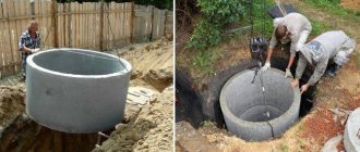
Fire storage facilities are designed as a prefabricated structure consisting of walls and a flat monolithic bottom. If the tank is small, then the walls are also monolithic (containers buried 2-3 meters). Underground storage facilities have a rectangular or round shape. They may differ in volume, depending on the objects served by the fire tank.
The base and outer wall of the container are treated with bituminous materials for waterproofing, the extending fragment can be banked (for thermal insulation), the upper part is covered with soil or slag. The inner surface is treated with shotcrete (calculation 1-1.5 cm). It is made from Portland cement or ceresite.
Where are they used?
The tanks are used in the oil refining industry.
Reinforced concrete tanks are used in the following areas of the economy:
- Water tanks. Used for the accumulation of sedimentary wastewater at municipal enterprises.
- Petroleum product storage facilities. They are used in enterprises to accumulate fuel and lubricants.
- Sewage storage facilities. For their storage and further processing of contaminated wastewater at industrial and housing and communal enterprises.
- Fire-fighting reservoirs. Water is accumulated for fire extinguishing at the bases of the Ministry of Emergency Situations.
- Industrial livestock farming. Accumulation and storage of waste from livestock breeding complexes.
Calculation of the strength of concrete determined that the concentration of moisture promotes hydration processes inside the material, which strengthens the storage.
Oil tanks
Underground oil tanks made of reinforced concrete are more reliable than metal ones. This makes it possible to use the space of tank farms more economically, since the space between tanks can be reduced. Mostly they are made in the shape of a cylinder, with a volume of 1000-40000 m3; fuel oil storage facilities are rectangular, their volume is up to 2000 m3.
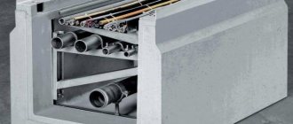
The designs of such containers take into account the drainage system under the bottom of the structure to check for possible leaks. They are also equipped with metering and skylights, inlet and distribution pipes, fuses, etc.
Typical projects for storage tanks
1. Standard design TP 903-3-03С.91. Storage tanks V=1; 1.6; 2.5; 4.0 m3. (BA-527.00.000). (full version)
- TP 903-3-03С.91. Album 1. Explanatory note. Bases for tanks. Installation of tanks. Anti-corrosion protection of tanks
- TP 903-3-03С.91. Album 2. Working drawings.
- TP 903-3-03С.91. Album 3. Estimates.
Calculate the cost of a 1 m3 storage tank Implemented projects
2. Standard design TP 903-3-03С.91. Accumulator tanks V=6.3 ÷ 100 m3. (BA-528.00.000). (full version)
- TP 903-3-03С.91. Album 1. Explanatory note. Bases for tanks. Installation of tanks. Anti-corrosion protection of tanks
- TP 903-3-03С.91. Album 2. Working drawings.
- TP 903-3-03С.91. Album 3. Estimates.
Calculate the cost of a 6.3 m3 storage tank Implemented projects
3. Standard design TP 903-9-28.89. Steel storage tank for hot water with a volume of 100 m3. (full version)
- TP 903-9-28.89. Album 1. Technological equipment. Lightning protection. Control and alarm. Thermal insulation protection.
- TP 903-9-28.89. Album 2. Anti-corrosion protection (from TP 903-9-26.89).
- TP 903-9-28.89. Album 3. Metal structures.
- TP 903-9-28.89. Album 4. Foundations and foundations.
- TP 903-9-28.89. Album 5. Thermal insulation.
- TP 903-9-28.89. Album 6. Basic provisions for installation work (from TP 903-9-26.89).
- TP 903-9-28.89. Album 7. Mounting connections (from TP 903-9-26.89).
- TP 903-9-28.89. Album 8. Statements of material requirements.
- TP 903-9-28.89. Album 9. Equipment specifications.
- TP 903-9-28.89. Album 10. Estimates.
- TP 903-9-28.89. Album 1. Steel protection structure (from TP 903-9-031.89).
Calculate the cost of a 100 m3 storage tank Implemented projects
4. Standard design TP 903-9-27.89. Steel storage tank for hot water with a volume of 200 m3. (full version)
- TP 903-9-27.89. Album 1. Technological equipment. Lightning protection. Control and alarm. Thermal insulation protection.
- TP 903-9-27.89. Album 2. Anti-corrosion protection (from TP 903-9-26.89).
- TP 903-9-27.89. Album 3. Metal structures.
- TP 903-9-27.89. Album 4. Foundations and foundations.
- TP 903-9-27.89. Album 5. Thermal insulation.
- TP 903-9-27.89. Album 6. Basic provisions for installation work (from TP 903-9-26.89).
- TP 903-9-27.89. Album 7. Mounting connections (from TP 903-9-26.89).
- TP 903-9-27.89. Album 8. Statements of material requirements.
- TP 903-9-27.89. Album 9. Equipment specifications.
- TP 903-9-27.89. Album 10. Estimates.
- TP 903-9-27.89. Album 1. Steel protection structure (from TP 903-9-031.89).
Calculate the cost of a 200 m3 storage tank Implemented projects
5. Standard design TP 903-9-26.89. Steel storage tank for hot water with a volume of 400 m3. (full version)
- TP 903-9-26.89. Album 1. Technological equipment. Lightning protection. Control and alarm. Thermal insulation protection.
- TP 903-9-26.89. Album 2. Anti-corrosion protection (from TP 903-9-26.89).
- TP 903-9-26.89. Album 3. Metal structures.
- TP 903-9-26.89. Album 4. Foundations and foundations.
- TP 903-9-26.89. Album 5. Thermal insulation.
- TP 903-9-26.89. Album 6. Basic provisions for installation work (from TP 903-9-26.89).
- TP 903-9-26.89. Album 7. Mounting connections (from TP 903-9-26.89).
- TP 903-9-26.89. Album 8. Statements of material requirements.
- TP 903-9-26.89. Album 9. Equipment specifications.
- TP 903-9-26.89. Album 10. Estimates.
- TP 903-9-26.89. Album 1. Steel protection structure (from TP 903-9-031.89).
Calculate the cost of a 400 m3 storage tank Implemented projects
6. Standard design TP 903-9-25.89. Steel storage tank for hot water with a volume of 700 m3. (full version)
- TP 903-9-25.89. Album 1. Technological equipment. Lightning protection. Control and alarm. Thermal insulation protection.
- TP 903-9-25.89. Album 2. Anti-corrosion protection (from TP 903-9-26.89).
- TP 903-9-25.89. Album 3. Metal structures.
- TP 903-9-25.89. Album 4. Foundations and foundations.
- TP 903-9-25.89. Album 5. Thermal insulation.
- TP 903-9-25.89. Album 6. Basic provisions for installation work (from TP 903-9-26.89).
- TP 903-9-25.89. Album 7. Mounting connections (from TP 903-9-26.89).
- TP 903-9-25.89. Album 8. Statements of material requirements.
- TP 903-9-25.89. Album 9. Equipment specifications.
- TP 903-9-25.89. Album 10. Estimates.
- TP 903-9-25.89. Album 1. Steel protection structure (from TP 903-9-031.89).
Calculate the cost of a 700 m3 storage tank Implemented projects
7. Standard design TP 903-9-24.89. Steel storage tank for hot water with a volume of 1000 m3. (full version)
- TP 903-9-24.89. Album 1. Technological equipment. Lightning protection. Control and alarm. Thermal insulation protection.
- TP 903-9-24.89. Album 2. Anti-corrosion protection (from TP 903-9-26.89).
- TP 903-9-24.89. Album 3. Metal structures.
- TP 903-9-24.89. Album 4. Foundations and foundations.
- TP 903-9-24.89. Album 5. Thermal insulation.
- TP 903-9-24.89. Album 6. Basic provisions for installation work (from TP 903-9-26.89).
- TP 903-9-24.89. Album 7. Mounting connections (from TP 903-9-26.89).
- TP 903-9-24.89. Album 8. Statements of material requirements.
- TP 903-9-24.89. Album 9. Equipment specifications.
- TP 903-9-24.89. Album 10. Estimates.
- TP 903-9-24.89. Album 1. Steel protection structure (from TP 903-9-031.89).
Calculate the cost of a 1000 m3 storage tank Implemented projects
8. Standard design TP 903-9-12sp86. Hot water storage tank for heating systems with a capacity of 2000 m3. (full version)
- TP 903-9-12sp86. Album 1. Technological equipment.
- TP 903-9-12sp86. Album 2. Anti-corrosion protection.
- TP 903-9-12sp86. Album 3. Metal structures.
- TP 903-9-12sp86. Album 4. Mobile stepladder. Working drawings.
- TP 903-9-12sp86. Album 5. Foundations and foundations.
- TP 903-9-12sp86. Album 6. Thermal insulation.
- TP 903-9-12sp86. Album 7. Thermal insulation structures and details.
- TP 903-9-12sp86. Album 8. Installation technology.
- TP 903-9-12sp86. Album 9. Installation accessories.
- TP 903-9-12sp86. Album 10. Estimates.
- TP 903-9-12sp86. Album 11. Statements of material requirements.
- TP 903-9-12sp86. Album 12. Equipment specification.
Calculate the cost of a 2000 m3 storage tank Implemented projects
9. Standard design TP 903-9-13sp86. Hot water storage tank for heating systems with a capacity of 3000 m3. (full version)
- TP 903-9-13sp86. Album 1. Technological equipment.
- TP 903-9-13sp86. Album 2. Anti-corrosion protection.
- TP 903-9-13sp86. Album 3. Metal structures.
- TP 903-9-13sp86. Album 4. Mobile stepladder. Working drawings.
- TP 903-9-13sp86. Album 5. Foundations and foundations.
- TP 903-9-13sp86. Album 6. Thermal insulation.
- TP 903-9-13sp86. Album 7. Thermal insulation structures and details.
- TP 903-9-13sp86. Album 8. Installation technology.
- TP 903-9-13sp86. Album 9. Installation accessories.
- TP 903-9-13sp86. Album 10. Estimates.
- TP 903-9-13sp86. Album 11. Statements of material requirements.
- TP 903-9-13sp86. Album 12. Equipment specification.
Calculate the cost of a 3000 m3 storage tank Implemented projects
10. Standard design TP 903-9-14sp86. Hot water storage tank for heating systems with a capacity of 5000 m3. (full version)
- TP 903-9-14sp86. Album 1. Technological equipment.
- TP 903-9-14sp86. Album 2. Anti-corrosion protection.
- TP 903-9-14sp86. Album 3. Metal structures.
- TP 903-9-14sp86. Album 4. Mobile stepladder. Working drawings (from TP 903-9-12sp.86).
- TP 903-9-14sp86. Album 5. Foundations and foundations.
- TP 903-9-14sp86. Album 6. Thermal insulation.
- TP 903-9-14sp86. Album 7. Thermal insulation structures (from TP 903-9-12sp.86).
- TP 903-9-14sp86. Album 8. Installation technology.
- TP 903-9-14sp86. Album 9. Installation accessories.
- TP 903-9-14sp86. Album 10. Estimates.
- TP 903-9-14sp86. Album 11. Statements of material requirements.
- TP 903-9-14sp86. Album 12. Equipment specification.
Calculate the cost of a 5000 m3 storage tank Implemented projects
What technological tests are carried out?
Tank design projects take into account testing to test the strength of the structure. To do this, the container is filled with water. This test takes place at an air temperature of 5 0 C. Before the test begins, pumps and pipelines are temporarily placed in reinforced concrete tanks. Every 12-15 meters of filling, level marks are made, thus checking the shrinkage of the container, and also making a full inspection of the entire structure. After complete filling, all hatches are checked for tight closure. The design of such work is drawn up in advance.
A typical project verification takes place in two stages:
- The container is filled up to 1 meter. After that, check for three days to see if the fluid level drops.
- Stage 2 lasts several days (usually about 5). Every day they fill a certain volume and monitor compliance with standards. After 8-12 hours, the marks are checked, a central deviation of more than 2.5 cm is considered unacceptable, volumetric standards for lowering losses are calculated at 1 dm 3 in the intermediate time, on the 3rd day - 3 dm 3, etc. Such calculations are carried out every day until passing the test.
If the tank has passed 2 stages of testing and all indicators were within acceptable standards and corresponded to the design, the storage facility is put into operation.
Standard designs for RGS tanks
1. Standard design TP 704-1-158.83. Horizontal cylindrical steel tank for storing petroleum products with a capacity of 3 m3. (full version)
- TP 704-1-158.83. Album 1. Steel structures for above-ground and underground installation
- TP 704-1-158.83. Album 2. Equipment of tanks for storing petroleum products with a saturated vapor pressure of 200-500 mm Hg for above-ground installation.
- TP 704-1-158.83. Album 3. Equipment of tanks for storing petroleum products with a saturated vapor pressure of 200-500 mmHg for underground installation in dry and wet soils.
- TP 704-1-158.83. Album 4. Equipment of tanks for storing petroleum products with a saturated vapor pressure of less than 200 mmHg when installed above ground.
- TP 704-1-158.83. Album 5. Equipment of tanks for storing petroleum products with a saturated vapor pressure of less than 200 mmHg for underground installation in dry and wet soils.
- TP 704-1-158.83. Album 6. Custom specifications.
- TP 704-1-158.83. Album 7. Estimates.
- TP 704-1-158.83. Album 8. List of materials.
Calculate the cost of a horizontal steel tank 3 m3 Completed projects
2. Standard design TP 704-1-159.83. Horizontal cylindrical steel tank for storing petroleum products with a capacity of 5 m3. (full version)
- TP 704-1-159.83. Album 1. Steel structures for above-ground and underground installation
- TP 704-1-159.83. Album 2. Equipment of tanks for storing petroleum products with a saturated vapor pressure of 200-500 mm Hg for above-ground installation.
- TP 704-1-159.83. Album 3. Equipment of tanks for storing petroleum products with a saturated vapor pressure of 200-500 mmHg for underground installation in dry and wet soils.
- TP 704-1-159.83. Album 4. Equipment of tanks for storing petroleum products with a saturated vapor pressure of less than 200 mmHg when installed above ground.
- TP 704-1-159.83. Album 5. Equipment of tanks for storing petroleum products with a saturated vapor pressure of less than 200 mmHg for underground installation in dry and wet soils.
- TP 704-1-159.83. Album 6. Custom specifications.
- TP 704-1-159.83. Album 7. Estimates.
- TP 704-1-159.83. Album 8. List of materials.
Calculate the cost of a horizontal steel tank 5 m3 Completed projects
3. Standard design TP 704-1-160.83. Horizontal cylindrical steel tank for storing petroleum products with a capacity of 10 m3. (full version)
- TP 704-1-160.83. Album 1. Steel structures for above-ground and underground installation
- TP 704-1-160.83. Album 2. Equipment of tanks for storing petroleum products with a saturated vapor pressure of 200-500 mm Hg for above-ground installation.
- TP 704-1-160.83. Album 3. Equipment of tanks for storing petroleum products with a saturated vapor pressure of 200-500 mmHg for underground installation in dry and wet soils.
- TP 704-1-160.83. Album 4. Equipment of tanks for storing petroleum products with a saturated vapor pressure of less than 200 mmHg when installed above ground.
- TP 704-1-160.83. Album 5. Equipment of tanks for storing petroleum products with a saturated vapor pressure of less than 200 mmHg for underground installation in dry and wet soils.
- TP 704-1-160.83. Album 6. Custom specifications.
- TP 704-1-160.83. Album 7. Estimates.
- TP 704-1-160.83. Album 8. List of materials.
Calculate the cost of a horizontal steel tank 10 m3 Completed projects
4. Standard design TP 704-1-161.83. Horizontal cylindrical steel tank for storing petroleum products with a capacity of 25 m3. (full version)
- TP 704-1-161.83. Album 1. Steel structures for above-ground and underground installation
- TP 704-1-161.83. Album 2. Equipment of tanks for storing petroleum products with a saturated vapor pressure of 200-500 mm Hg for above-ground installation.
- TP 704-1-161.83. Album 3. Equipment of tanks for storing petroleum products with a saturated vapor pressure of 200-500 mmHg for underground installation in dry and wet soils.
- TP 704-1-161.83. Album 4. Equipment of tanks for storing petroleum products with a saturated vapor pressure of less than 200 mmHg when installed above ground.
- TP 704-1-161.83. Album 5. Equipment of tanks for storing petroleum products with a saturated vapor pressure of less than 200 mmHg for underground installation in dry and wet soils.
- TP 704-1-161.83. Album 6. Custom specifications.
- TP 704-1-161.83. Album 7. Estimates.
- TP 704-1-161.83. Album 8. List of materials.
Calculate the cost of a horizontal steel tank 25 m3 Completed projects
5. Standard design TP 704-1-162.83. Horizontal cylindrical steel tank for storing petroleum products with a capacity of 50 m3. (full version)
- TP 704-1-162.83. Album 1. Steel structures for above-ground and underground installation
- TP 704-1-162.83. Album 2. Equipment of tanks for storing petroleum products with a saturated vapor pressure of 200-500 mm Hg for above-ground installation.
- TP 704-1-162.83. Album 3. Equipment of tanks for storing petroleum products with a saturated vapor pressure of 200-500 mmHg for underground installation in dry and wet soils.
- TP 704-1-162.83. Album 4. Equipment of tanks for storing petroleum products with a saturated vapor pressure of less than 200 mmHg when installed above ground.
- TP 704-1-162.83. Album 5. Equipment of tanks for storing petroleum products with a saturated vapor pressure of less than 200 mmHg for underground installation in dry and wet soils.
- TP 704-1-162.83. Album 6. Custom specifications.
- TP 704-1-162.83. Album 7. Estimates.
- TP 704-1-162.83. Album 8. List of materials.
Calculate the cost of a horizontal steel tank 50 m3 Completed projects
6. Standard design TP 704-1-163.83. Horizontal cylindrical steel tank for storing petroleum products with a capacity of 75 m3. (full version)
- TP 704-1-163.83. Album 1. Steel structures for above-ground and underground installation
- TP 704-1-163.83. Album 2. Equipment of tanks for storing petroleum products with a saturated vapor pressure of 200-500 mm Hg for above-ground installation.
- TP 704-1-163.83. Album 3. Equipment of tanks for storing petroleum products with a saturated vapor pressure of 200-500 mmHg for underground installation in dry and wet soils.
- TP 704-1-163.83. Album 4. Equipment of tanks for storing petroleum products with a saturated vapor pressure of less than 200 mmHg when installed above ground.
- TP 704-1-163.83. Album 5. Equipment of tanks for storing petroleum products with a saturated vapor pressure of less than 200 mmHg for underground installation in dry and wet soils.
- TP 704-1-163.83. Album 6. Custom specifications.
- TP 704-1-163.83. Album 7. Estimates.
- TP 704-1-163.83. Album 8. List of materials.
Calculate the cost of a horizontal steel tank 75 m3 Completed projects
7. Standard design TP 704-1-164.83. Horizontal cylindrical steel tank for storing petroleum products with a capacity of 100 m3. (full version)
- TP 704-1-164.83. Album 1. Steel structures for above-ground and underground installation
- TP 704-1-164.83. Album 2. Equipment of tanks for storing petroleum products with a saturated vapor pressure of 200-500 mm Hg for above-ground installation.
- TP 704-1-164.83. Album 3. Equipment of tanks for storing petroleum products with a saturated vapor pressure of 200-500 mmHg for underground installation in dry and wet soils.
- TP 704-1-164.83. Album 4. Equipment of tanks for storing petroleum products with a saturated vapor pressure of less than 200 mmHg when installed above ground.
- TP 704-1-164.83. Album 5. Equipment of tanks for storing petroleum products with a saturated vapor pressure of less than 200 mmHg for underground installation in dry and wet soils.
- TP 704-1-164.83. Album 6. Custom specifications.
- TP 704-1-164.83. Album 7. Estimates.
- TP 704-1-164.83. Album 8. List of materials.
Calculate the cost of a horizontal steel tank 100 m3 Completed projects