STATE STANDARD OF THE USSR UNION
REINFORCED CONCRETE MULTI-HOLLOW FLOORS PLATES FOR BUILDINGS AND STRUCTURES
TECHNICAL CONDITIONS
GOST 9561-91
USSR STATE COMMITTEE FOR CONSTRUCTION AND INVESTMENT
Moscow
STATE STANDARD OF THE USSR UNION
| REINFORCED CONCRETE MULTI-HOLLOW FLOORS PLATES FOR BUILDINGS AND STRUCTURES Specifications Reinforced concrete multihollow panels for floors in buildings. Specifications | GOST 9561-91 |
Date of introduction 01/01/92
This standard applies to reinforced concrete hollow-core slabs (hereinafter referred to as slabs), made from heavy, light and dense silicate concrete and intended for the load-bearing part of the floors of buildings and structures for various purposes.
The slabs are used in accordance with the instructions of the working drawings of the slabs and additional requirements specified when ordering these structures.
ACCEPTANCE
2.1. Acceptance of slabs is in accordance with GOST 13015.1 and this standard. In this case, the slabs are accepted based on the results:
periodic testing - in terms of strength, rigidity and crack resistance of slabs, frost resistance of concrete, porosity (volume of intergranular voids) of a compacted mixture of lightweight concrete, as well as water resistance of concrete slabs intended for use in conditions of exposure to an aggressive environment;
acceptance tests - in terms of concrete strength (class or grade of concrete in terms of compressive strength, transfer and tempering strengths), average density of light or dense silicate concrete, compliance of reinforcement and embedded products with working drawings, strength of welded joints, accuracy of geometric parameters, thickness of the protective layer concrete to reinforcement, the opening width of technological cracks and the category of the concrete surface.
2.2. Periodic loading tests of slabs to control their strength, rigidity and crack resistance are carried out before the start of their mass production and in the future - when design changes are made to them and when manufacturing technology changes, as well as during the mass production of slabs at least once a year. Load testing of slabs in the event of structural changes being made to them and when manufacturing technology is changed, depending on the essence of these changes, may not be carried out in agreement with the design organization that developed the working drawings of the slabs.
Testing of slabs with a length of 5980 mm or less during their serial production may not be carried out if non-destructive testing is carried out in accordance with the requirements of GOST 13015.1.
2.3. Slabs in terms of the accuracy of geometric parameters, the thickness of the protective layer of concrete before the reinforcement, the width of the opening of technological cracks and the category of the concrete surface should be accepted based on the results of random inspection.
2.4. The porosity (volume of intergranular voids) of a compacted mixture of lightweight concrete should be determined at least once a month.
2.5. The document on the quality of slabs intended for use in conditions of exposure to aggressive environments must additionally indicate the grade of concrete for water resistance (if this indicator is specified in the order for the production of slabs).
Prefabricated reinforced concrete floors made of hollow slabs: nuances of selection and installation
When building a house, any developer faces the question of choosing an interfloor floor. The three most common types of floors are wooden, monolithic reinforced concrete and prefabricated reinforced concrete, mounted from flat hollow-core slabs. It is this type of flooring, as the most popular and practical for low-rise construction, that will be discussed in this material. From this about interfloor ceilings in a private house you will learn:
- What is the difference between hollow-core floor slabs (PC) and floor slabs made by formless molding (PB).
- How to lay floors correctly.
- How to avoid installation mistakes.
- How to store floor slabs.
How to choose a hollow core slab
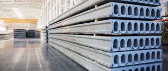
At first glance at hollow-core floors, it may seem that they differ from each other only in length, thickness and width. But the technical characteristics of hollow core floor slabs are much broader and are described in detail in GOST 9561-91.
Hollow core slab, private house.
Hollow-core interfloor slabs differ from each other in the method of reinforcement. Moreover, reinforcement (depending on the type of slabs) can be performed using prestressed reinforcement or without prestressed reinforcement. More often, floors with prestressed working reinforcement are used.
When choosing floor slabs, you should pay attention to such an important point as the permissible number of sides on which they can be supported. . Usually you can only support on two short sides, but some types of slabs allow support on three or four sides.
- PB. Provides support on two sides;
- 1pc. Thickness – 220 mm. The diameter of the round voids is 159 mm. Allows support on two sides only;
- 1PKT. Having similar dimensions, it allows support on three sides;
- 1PKK. Can be leaned on four sides.
Floor slabs also differ in their manufacturing method. There is often a debate about what to prefer – PC or PB.
Andrey164FORUMHOUSE user
The time has come to cover the basement floor of the building with floor slabs, but I can’t decide what to choose - PC or PB, PB has a better surface finish than PC, but I heard that PB are used only in monolithic-frame houses and country houses, and the end Such slabs cannot be loaded with a wall.
Sasha1983 FORUMHOUSE user
The main difference between the plates lies in the technology of their manufacture.
PC (thickness from 160 to 260 mm and typical load-bearing capacity of 800 kg/sq.m.) is cast in formwork. PB brand panels (thickness from 160 mm to 330 mm and typical load-bearing capacity from 800 kg/sq.m) are manufactured using formless continuous casting (this allows for a smoother and more even surface than PC panels). PBs are also called extruder ones.
PB, due to prestressing of the compressed and tensile zones (prestressing of the reinforcement is done at any length of the slab), is less susceptible to cracking than PC. PCs with a length of up to 4.2 meters can be produced without prestressed reinforcement and have a greater free deflection than PB.
At the customer's request, PB can be cut to individual specified sizes (from 1.8 to 9 meters, etc.). They can also be cut lengthwise and into individual longitudinal elements, as well as making an oblique cut at an angle of 30-90 degrees, without losing its load-bearing capacity. This greatly simplifies the layout of such floor slabs on a construction site and provides greater freedom to the designer, because The dimensions of the building box and load-bearing walls are not tied to standard PC dimensions.
When choosing PC interfloor slabs (more than 4.2 meters long), it is important to remember this feature - they are prestressed with special stops at the ends of the slab. If you cut off the end of the PC, the stop (cut off together with the end of the PC and the vertical reinforcement) will not work. Accordingly, the working reinforcement will cling to the concrete only with its side surface. This will significantly reduce the load-bearing capacity of the slab.
Despite the better quality smooth surface, good geometry, lighter weight and high load-bearing capacity, this point should be taken into account when choosing a PB. Hollow holes in the PC (depending on the width of the slab, with a diameter of 114 to 203 mm) make it possible to easily punch a hole in it for a sewer riser with a diameter of 100 mm. While the size of the void hole in the PB is 60 mm. Therefore, to punch a through hole in a PB brand panel (so as not to damage the reinforcement), you should check with the manufacturer in advance on how best to do this.
Floor slabs for a private house: installation features
PB (unlike PC) does not have mounting loops (or you have to pay extra for their installation), which can complicate their loading, unloading and installation.
It is not recommended to use the “folk” method of installing the PB, when the fastening hooks cling to the end of the hollow hole. In this case, there is a high probability that the hook will be torn out of the hole due to the destruction of the end of the slab, or the hook will simply slip off. This will cause the slab to fall. Also, at your own peril and risk, you can use a method in which a crowbar is inserted into the hollow holes of the PB (two crowbars on one side of the slab) and hooks cling to them.
Installation of PB slabs is allowed only with the use of soft chocks or a special traverse.
ProgCUser FORUMHOUSE
To pull the joist out from under the slab, when laying it, leave a gap of 2 cm to the adjacent slab. Then we move the already laid slab with a crowbar to the adjacent one.
Max_imUser FORUMHOUSE
Personal experience: I laid slabs at my construction site using this method. The gap was left at 3 cm. The slabs were laid on a cement-sand mixture 2 cm thick. The mixture acted as a lubricant, and the slabs were easily moved with a crowbar to the distance I needed.
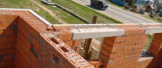
Also, when installing floor slabs, it is necessary to comply with the calculated values of the minimum depth of support for the slab. The following numbers can be used as a guide:
- brick wall, minimum support depth is 8 cm, maximum support depth is 16 cm;
- reinforced concrete – 7 cm, maximum support depth – 12 cm;
- gas and foam concrete blocks - at least 10-12 cm, optimal support depth - 15 cm;
- steel structures – 7 cm.
It is not recommended to support the floor slab more than 20 cm, because as the depth of support increases, it begins to “work” like a pinched beam. When laying floor panels on walls built from aerated and foam concrete blocks, it is necessary to install a reinforced concrete armored belt, which is described in detail in the article: “Making an armored belt in a house made of aerated concrete.” About
CONTROL METHODS
3.1. Load tests of slabs to control their strength, rigidity and crack resistance should be carried out in accordance with the requirements of GOST 8829 and working drawings of these slabs.
3.2. The strength of concrete slabs should be determined according to GOST 10180 on a series of samples made from a concrete mixture of the working composition and stored under the conditions established by GOST 18105.
When determining the strength of concrete using non-destructive testing methods, the actual transfer and tempering compressive strength of concrete is determined by the ultrasonic method in accordance with GOST 17624 or mechanical devices in accordance with GOST 22690. It is permissible to use other non-destructive testing methods provided for by the standards for concrete testing methods.
3.3. The frost resistance of concrete slabs should be determined according to GOST 10060 or by the ultrasonic method according to GOST 26134 on a series of samples made from a concrete mixture of the working composition.
3.4. The water resistance of concrete slabs intended for operation in conditions of exposure to aggressive environments should be determined according to GOST 12730.0 and GOST 12730.5.
3.5. The average density of light and dense silicate concrete should be determined according to GOST 12730.0 and GOST 12730.1 or by the radioisotope method according to GOST 17623.
3.6. The porosity indicators of a compacted mixture of lightweight concrete should be determined according to GOST 10181.0 and GOST 10181.3.
3.7. Inspection of welded reinforcement and embedded products - in accordance with GOST 10922 and GOST 23858.
3.8. The tension force of the reinforcement, controlled at the end of the tension, is measured according to GOST 22362.
3.9. The dimensions of the slabs, deviations from the straightness and flatness of the surfaces of the slabs, the width of the opening of technological cracks, the sizes of cavities, sagging and edges of concrete slabs should be determined by the methods established by GOST 26433.0 and GOST 26433.1.
3.10. The dimensions and position of reinforcement and embedded products, as well as the thickness of the protective layer of concrete up to the reinforcement, should be determined according to GOST 17625 and GOST 22904. In the absence of the necessary equipment, cutting furrows and exposing the slab reinforcement with subsequent sealing of the furrows is allowed. Furrows should be punched at a distance from the ends not exceeding 0.25 times the length of the slab.
Decoding the concept
This modification of ready-made reinforced concrete floor elements has a limited thickness of up to 300 mm ; inside the structure there are several through voids of a cylindrical shape D = 159 mm, directed along the long side of the structure.
For the production of PCs, M30/M400 concrete mortar is used, which provides the structure with the necessary strength and ductility.
In order to increase the strength properties and load-bearing capacity of hollow-core floors, a reinforced frame made of stressed steel reinforcement A3 and A4 class is installed in them .
Such a frame is reinforced at the ends to prevent deformation of the structure in the area of increased load.
For what purposes are they used?
The PC modification is used in industrial, commercial and residential construction. In addition, they are used in the construction of heating mains and tunnels. The slabs are widely used for large-panel objects, but there are certain modifications for private buildings built from standard brick, as well as lightweight concrete blocks.
Important! PCs are applicable for any climatic regions, including zones with increased seismic activity. In the latter case, the slabs are made from concrete with special additives and a reinforced reinforcement frame.
TRANSPORTATION AND STORAGE
4.1. Transportation and storage of slabs - in accordance with GOST 13015.4 and this standard.
4.2. The slabs should be transported and stored in stacks laid in a horizontal position.
On specialized vehicles it is allowed to transport slabs in an inclined or vertical position.
4.3. The height of the stack of slabs should not be more than 2.5 m.
4.4. Pads for the bottom row of slabs and spacers between them in a stack should be located near the mounting loops.
Advantages and disadvantages
If we compare PCs with solid slabs, the first has significant advantages :
- Low overall weight of the slab.
- The ability to use the structure for its intended purpose with design loads, almost immediately after installation, since no time is required for the concrete solution to harden.
- Reducing the load on the foundation of the house and walls.
- Providing characteristics of strength, heat resistance and noise protection, since the cylindrical holes act on the one hand as additional stiffening ribs, and on the other as air insulators that prevent the transfer of heat losses and sound waves between floors.
- Increase the usable volume in the room.
- Good resistance to seismic loads.
- Reducing construction time.
- Reducing the cost of finishing work.
- Reducing the specific costs of concrete and steel for the production of 1 m2 of flooring.
- Reduced transportation costs.
- Reducing the cost of 1 m2 of construction.
The disadvantages of hollow-core slabs include a low range of external dimensions, which complicates installation in houses with non-standard layouts, as well as the need to use lifting equipment to perform installation work.
LIST OF SIZES AND SERIES OF WORKING DRAWINGS OF PLATES FOR MASSIVE APPLICATION
Table 4
| Slab size | Designation of a series of working drawings of slabs |
| 1PK90.15 | 1.241-1 |
| 1PK90.12 | |
| 1PK90.10 | |
| 1PK86.15 | 1.041.1-3 |
| 1PK86.12 | |
| 1PK86.9 | |
| 1PK72.15 | 1.241-1; 1.090.1-1; 1.090.1-2s; 1.090.1-3pv; 1.090.1-5s |
| 1PK72.12 | |
| 1PK71.15 | 1.141-18s; 1.141.1-25s; 1.141.1-32s |
| 1PK71.12 | |
| 1PK71.10 | |
| 1PK68.15 | 1.041.1-3 |
| 1PK68.12 | |
| 1PK68.9 | |
| 1PK66.15 | 1.241-1; 1.090.1-1 |
| 1PK66.12 | |
| 1PK66.10 | 1.241-1 |
| 1PK63.30 | 1.241-1 |
| 1PK63.24 | |
| 1PK63.18 | 1.141-1; 1.141.1-33s |
| 1PK63.15 | 1.141-1; 1.141.1-30; 1.141.1-33s |
| 1PK63.12 1PK63.10 | 1.141-1; 1.141.1-33s |
| 1PK62.15 | 1.141-18s; 1.141.1-25s; 1.141.1-32s |
| 1PK62.12 | |
| 1PK62.10 | |
| 1PK60.18 | 1.141-1; 1.141.1-33s |
| 1PK60.15 | 1.141-1; 1.141.1-33с; 1.090.1-2s; 1.090.1-3pv; 1.090.1-5s |
| 1PK60.12 | |
| 1PK60.10 | 1.141-1; 1.141.1-33s |
| 1PK59.15 | 1.141-18s; 1.141.1-25s; 1.141.1-32s |
| 1PK59.12 | |
| 1PK59.10 | |
| 1PK57.18 | 1.141-1 |
| 1PK57.15 | |
| 1PK57.12 | |
| 1PK57.10 | |
| 1PK56.30 | 1.041.1-3 |
| 1PK56.15 | |
| 1PK.56.12 | |
| 1PK56.9 | |
| 1PK54.18 | 1.141-1; 1.141.1-33s |
| 1PK54.15 | |
| 1PK54.12 | |
| 1PK54.10 | |
| 1PK51.18 | 1.141-1; 1.141.1-33s |
| 1PK51.15 | 1.141-1; 1.141.1-33с; 1.141.1-30 |
| 1PK51.12 | 1.141-1; 1.141.1-33s |
| 1PK51.10 | |
| 1PK48.18 | 1.141-1; 1.141.1-33s |
| 1PK48.15 | 1.141.1; 1.141.1-33с; 1.141.1-30 |
| 1PK48.12 | 1.141-1; 1.141.1-33s |
| 1PK48.10 | |
| 1PK47.15 | 1.141-18s; 1.141.1-25s; 1.141.1-32s |
| 1PK47.12 | |
| 1PK47.10 | |
| 1PK42.18 | 1.141-1 |
| 1PK42.15 | |
| 1PK42.12 | |
| 1PK42.10 | |
| 1PK39.18 | 1.141-1 |
| 1PK39.15 | |
| 1PK39.12 | |
| 1PK39.10 | |
| 1PK36.18 | 1.141-1 |
| 1PK36.15 | |
| 1PK36.12 | |
| 1PK36.10 | |
| 1PK33.30 | 1.241-1 |
| 1PK33.24 | |
| 1PK30.18 | 1.141-1 |
| 1PK30.15 | 1.141-1; 1.090.1-1; 1.090.1-2s; 1.090.1-3pv; 1.090.1-5s |
| 1PK30.12 | |
| 1PK30.10 | 1.141-1 |
| 1PK29.18 | 1.141.1-28с; 1.141.1-29с |
| 1PK29.15 | |
| 1PK29.12 | |
| 1PK29.10 | |
| 1PK27.15 | 1.041.1-3 |
| 1PK27.12 | |
| 1PK27.9 | |
| 1PK24.18 | 1.141-1 |
| 1PC24.15 | 1.141-1; 1.090.1-1; 1.090.1-2s; 1.090.1-3pv; 1.090.1-5s |
| 1PK24.12 | |
| 1PC24.10 | 1.141-1 |
| 1PC23.18 | 1.141.1-28с; 1.141.1-29с |
| 1PC23.15 | |
| 1PC23.12 | |
| 1PC23.12 | |
| 1PC23.10 | |
| 2PK60.36 | 141; E-600; E-600IV; E600II TsNIIEP housing |
| 2PK60.35 | |
| 2PK60.30 | |
| 2PK60.26 | |
| 2PK60.24 | |
| 2PK60.18 | |
| 2PK60.12 | |
| 2PK30.66 | |
| 2PK30.60 | |
| 2PK30.54 | |
| 2PK30.48 | |
| 2PK30.18 | |
| 2PK30.12 | |
| 3PK63.30 | 135 KB on reinforced concrete named after. A.A. Yakusheva |
| 3PK63.18 | |
| 3PK63.12 | |
| 3PK30.30 | |
| 3PK30.18 | |
| 3PK30.12 | |
| 4PK86.15 | 86-3191/1 TsNIIEP of commercial and household buildings and tourist complexes |
| 4PK86.12 | |
| 4PK86.9 | |
| 4PK72.15 | 1.090.1-1 |
| 4PK72.12 | |
| 4PK68.15 | 86-3191/1 TsNIIEP of commercial and household buildings and tourist complexes |
| 4PK68.12 | |
| 4PK68.9 | |
| 4PK66.15 | 1.090.1-1 |
| 4PK66.12 | |
| 4PK60.15 | |
| 4PK60.12 | |
| 4PK56.15 | 86-3191/1 TsNIIEP of commercial and household buildings and tourist complexes |
| 4PK56.12 | |
| 4PK56.9 | |
| 4PK30.15 | 1.090.1-1 |
| 4PK30.12 | |
| 4PK26.15 | 86-3191/1 TsNIIEP of commercial and household buildings and tourist complexes |
| 4PK26.12 | |
| 4PK26.9 | |
| 5PK116.15 | 1.041.1-3 |
| 5PK116.12 | |
| 5PK116.9 | |
| 5PK86.15 | 1.041.1-3 |
| 5PK86.12 | |
| 5PK86.9 | |
| 5PK56.15 | 1.041.1-3 |
| 5PK56.12 | |
| 5PK56.9 | |
| 6PK120.15 | 1.241-1 |
| 6PK120.12 | |
| 6PK120.10 | |
| 7PK63.18 | 1.141.1-39 |
| 7PK63.12 | |
| 7PK60.18 | 1.141.1-39 |
| 7PK60.12 | |
| 7PK51.18 | 1.141.1-39 |
| 7PK51.12 | |
| 7PK48.18 | 1.141.1-39 |
| 7PK48.12 | |
| 7PK36.18 | 1.141.1-39 |
| 7PK36.12 | |
| PG116.15 | 28-87 TsNIIpromzdany |
| PG116.12 | |
| PG116.9 | |
| PG86.15 | |
| PG86.12 | |
| PG86.9 | |
| PG56.15 | |
| PG56.12 | |
| PG56.9 |
AREA OF APPLICATION OF VARIOUS TYPES OF PLATES
Table 5
| Slab type | Reduced slab thickness, m | Average density of concrete slab, kg/m3 | Slab length, m | Characteristics of buildings (structures) |
| 1pc | 0,12 | 1400 — 2500 | Up to 7.2 incl. | Residential buildings in which the required sound insulation of residential premises is ensured by the installation of hollow-core, floating, hollow-core layered floors, as well as single-layer floors on a leveling screed |
| 1PKT | ||||
| 1PKK | ||||
| 1pc | Up to 9.0 incl. | Public and industrial buildings (structures) | ||
| 2pcs | 0,16 | 2200 — 2500 | Up to 7.2 incl. | Residential buildings in which the required sound insulation of residential premises is ensured by installing single-layer floors |
| 2PKT | ||||
| 2PKK | ||||
| 3pcs | Up to 6.3 incl. | Residential large-panel buildings of the 135 series, in which the required sound insulation of the premises is ensured by installing single-layer floors | ||
| 3PKT | ||||
| 3PKK | ||||
| 4pcs | 0,16 | 1400 — 2500 | Up to 9.0 incl. | Public and industrial buildings (structures) |
| 5pcs | 0,17 | 2200 — 2500 | Up to 12.0 incl. | |
| 6pcs | 0,15 | |||
| PG | 0,15 | |||
| 7pcs | 0,09 | 2200 — 2500 | Up to 7.2 incl. | Low-rise and estate-type residential buildings |
Requirements according to GOST
The basic regulatory document for reinforced concrete floors of PCs is GOST No. 26434, published in 2015. Also applicable :
- 13015-2012;
- 21779-82;
- GOST 23009-2016.
They regulate modifications of factory products, their sizes and production characteristics :
Length range from 1.7 to 12 m.- Range of standard sizes in width: 1.0-3.6 m.
- Variation in thickness: 160-300 mm.
- Weight from 0.800-8.600 t.
- Permitted load on PC: 3-13 kPa.
- Types of concrete: heavy, dense silicate and light.
- Design size between voids at centers: 139-233 mm.
- Number of support zones: 2, 3 and 4.
- Reinforcement - prestressed/non-prestressed.
