UDC 692.297:691.328:006.354
GOST 18979-2014
INTERSTATE STANDARD
REINFORCED CONCRETE COLUMNS FOR MULTISTORY BUILDINGS
Specifications
Reinforced concrete columns for multistory buildings. Specification
MKS 91.080.40
Date of introduction 2015-07-01
Preface
The goals, basic principles and basic procedure for carrying out work on interstate standardization are established by GOST 1.0-92 “Interstate standardization system. Basic provisions" and GOST 1.2-2009 "Interstate standardization system. Interstate standards, rules and recommendations for interstate standardization. Rules for the development, adoption, application, updating and about TsNIIPromzdaniya")
2 INTRODUCED by the Technical Committee for Standardization TC 465 “Construction”
3 ADOPTED by the Interstate Council for Standardization, Metrology and Certification (protocol dated September 30, 2014 N 70-P)
The following voted for adoption:
| Short name of the country according to MK (ISO 3166) 004-97 | Country code according to MK (ISO 3166) 004-97 | Abbreviated name of the state construction management body |
| Armenia | A.M. | Ministry of Economy of the Republic of Armenia |
| Kyrgyzstan | KG | Kyrgyzstandard |
| Moldova | M.D. | Moldova-Standard |
| Russia | RU | Rosstandart |
4 By Order of the Federal Agency for Technical Regulation and Metrology dated October 22, 2014 N 1373-st, the interstate standard GOST 18979-2014 was put into effect as a national standard of the Russian Federation on July 1, 2015.
5 INSTEAD GOST 18979-90
Information about changes to this standard is published in the annual information index “National Standards”, and the text of changes and amendments is published in the monthly information index “National Standards”. In case of revision (replacement) or cancellation of this standard, the corresponding notice will be published in the monthly information index “National Standards”. Relevant information, notifications and texts are also posted in the public information system - on the official website of the Federal Agency for Technical Regulation and Metrology on the Internet
1 area of use
1.1 This standard establishes requirements for the manufacture of reinforced concrete columns of solid rectangular cross-section from heavy concrete intended for the frames of multi-storey public buildings, industrial, administrative and domestic buildings of industrial enterprises.
1.2 This standard applies to columns used:
in heated buildings and structures;
in unheated buildings and structures and in the open air at the design temperature of the outside air (average air temperature for 5 days at the lowest temperature in the construction area) up to minus 40°C inclusive;
under conditions of systematic exposure to elevated process temperatures up to 50°C inclusive;
with non-aggressive, weakly and moderately aggressive degrees of influence of gaseous media on reinforced concrete structures;
in buildings and structures erected in non-seismic and seismic areas (with a calculated seismicity of up to 9 points inclusive);
for the construction of buildings on subsidence, permafrost soils and undermined areas.
1.3 In unheated buildings and structures and in the open air at a design outside air temperature below minus 40°C, under conditions of systematic exposure to process temperatures above 50°C, as well as at a design seismicity of 9 points, the use of columns is possible subject to additional requirements established by the design documentation a specific building or structure (in accordance with current regulatory documents) and specified in the order for the manufacture of columns.
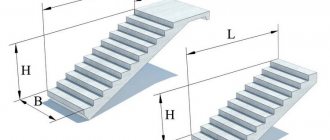
Appendix A (recommended). Shape and main dimensions of columns
Appendix A (recommended)
1 The shape and main dimensions of the columns are given:
cross-section 400×400 mm of a braced frame for interspecific use for public buildings, industrial, administrative and domestic buildings of industrial enterprises [1] - in Figures 1-4 and Table A.1;
cross-section 400×400 mm of a frame frame for interspecific use for public buildings, industrial, administrative and domestic buildings of industrial enterprises [2] - in Figures 5-8 and in Table A.2;
cross-section 400×600 mm of frame frames of industrial buildings erected in non-seismic areas and in areas with seismicity 7-9 points [3] - in Figures 9-14 and in Table A.Z;
cross-section 400×600 mm of frame frames of industrial buildings erected in non-seismic areas and in areas with seismicity 7-9 points [3] - in Figures 9-14 and in Table A.Z;
cross-section 400×400 mm and lower columns with a cross-section varying in height 400×600 mm by 400×400 mm frame frames of industrial buildings, [4] - in Figures 15-19 and Table A.4.
Table A.1 - Columns with a cross section of 400×400 mm of a braced frame for interspecific use for public buildings, industrial, administrative and domestic buildings of industrial enterprises (formwork forms of the 1.020-1/87 series)
| Column size | Main column size, mm | Figure number | |||
| I | I1 | I2 | I3 | ||
| 1KV33.1 | 2550 | — | — | — | 1 |
| 1KV36.1 | 2920 | — | — | — | |
| 1KV42.1 | 3520 | — | — | — | |
| 1KV48.1 | 4120 | — | — | — | |
| 2KV33.1 | 5850 | — | — | — | |
| 2KV36.1 | 6520 | — | — | — | |
| 2KV42.1 | 7720 | — | — | — | |
| 2KV48.1 | 8920 | — | — | — | |
| 3КB33.1 | 9150 | — | — | — | |
| 3KB36.1 | 10120 | — | — | — | |
| ZKV42.1 | 11920 | — | — | — | |
| ZKV48.1 | 13720 | — | — | — | |
| 1KVO33.1 | 2550 | 2250 | — | 300 | |
| 1KVO36.1 | 2920 | 2550 | — | 370 | |
| 1KVO42.1 | 3520 | 3150 | — | ||
| 1KVO48.1 | 4120 | 3750 | — | ||
| 1KVO54.1 | 4720 | 4350 | — | ||
| 1KVO60.1 | 5320 | 4950 | — | ||
| 2KVO33.1 | 5850 | 2250 | 3300 | 300 | |
| 2KVO36.1 | 6520 | 2550 | 3600 | 370 | |
| 2KVO42.1 | 7720 | 3150 | 4200 | ||
| 2KVO48.1 | 8920 | 3750 | 4800 | ||
| 2KVO60.1 | 11320 | 4950 | 6000 | ||
| ZKVO33.1 | 9150 | 2250 | 3300 | 300 | |
| ZKVO36.1 | 10120 | 2550 | 3600 | 370 | |
| ZKVO42.1 | 11920 | 3150 | 4200 | ||
| ZKVO48.1 | 13720 | 3750 | 4800 | ||
| 1KVD33.1 | 2550 | 2250 | — | 300 | |
| 1KVD36.1 | 2920 | 2550 | — | 370 | |
| 1KVD42.1 | 3520 | 3150 | — | ||
| 1KVD48.1 | 4120 | 3750 | — | ||
| 1KVD54.1 | 4720 | 4350 | — | ||
| 1KVD60.1 | 5320 | 4950 | — | ||
| 2KVD33.1 | 5850 | 2250 | 3300 | 300 | |
| 2KVD36.1 | 6520 | 2550 | 3600 | 370 | |
| 2KVD42.1 | 7720 | 3150 | 4200 | ||
| 2KVD48.1 | 8920 | 3750 | 4800 | ||
| 2KVD60.1 | 11320 | 4950 | 6000 | ||
| ZKVD33.1 | 9150 | 2250 | 3300 | 300 | |
| ZKVD36.1 | 10120 | 2550 | 3600 | 370 | |
| ZKVD42.1 | 11920 | 3150 | 4200 | ||
| ZKVD48.1 | 13720 | 3750 | 4800 | ||
| 1KS33.1 | 3300 | — | — | — | 2 |
| 1KS36.1 | 3600 | — | — | — | |
| 1KS42.1 | 4200 | — | — | — | |
| 1KS48.1 | 4800 | — | — | — | |
| 2KS42.1 | 8400 | — | — | — | |
| 2KS48.1 | 9600 | — | — | — | |
| 3КC33.1 | 9900 | — | — | — | |
| 3КC36.1 | 10800 | — | — | — | |
| 1KSO33.1 | 3300 | 2250 | — | 1050 | |
| 1KSO36.1 | 3600 | 2550 | — | ||
| 1KSO42.1 | 4200 | 3150 | — | ||
| 1KSO48.1 | 4800 | 3750 | — | ||
| 1KSO54.1 | 5400 | 4350 | — | ||
| 1KSO60.1 | 6000 | 4950 | — | ||
| 2KSO42.1 | 8400 | 3150 | 4200 | 1050 | |
| 2KSO48.1 | 9600 | 3750 | 4800 | ||
| 2KSO60.1 | 12000 | 4950 | 6000 | ||
| ZKSOZZ.1 | 9900 | 2250 | 3300 | 1050 | |
| ZKSZ6.1 | 10800 | 2550 | 3600 | ||
| 1KSD33.1 | 3300 | 2250 | — | 1050 | |
| 1KSD36.1 | 3600 | 2550 | — | ||
| 1KSD42.1 | 4200 | 3150 | — | ||
| 1KSD48.1 | 4800 | 3750 | — | ||
| 1KSD54.1 | 5400 | 4350 | — | ||
| 1KSD60.1 | 6000 | 4950 | — | ||
| 2KSD42.1 | 8400 | 3150 | 4200 | 1050 | |
| 2KSD48.1 | 9600 | 3750 | 4800 | ||
| 2KSD60.1 | 12000 | 4950 | 6000 | ||
| 3KSD33.1 | 9900 | 2250 | 3300 | 1050 | |
| 3KSD36.1 | 10800 | 2550 | 3600 | ||
| 1KN33(30)1 | 4550 | — | — | — | 3 |
| 1KN33.1 | 5050 | — | — | — | |
| 1KN36.1 | 5350 | — | — | — | |
| 1KN42.1 | 5950 | — | — | — | |
| 2KN33(20)1 | 6650 | — | — | — | |
| 2KN42(20)1 | 7550 | — | — | — | |
| 2KN33(30)1 | 7850 | — | — | — | |
| 2KN42(30)1 | 8750 | — | — | — | |
| 2KN36(48)1 | 9650 | — | — | — | |
| 2KN42.1 | 10150 | — | — | — | |
| 2KN48.1 | 10850 | — | — | — | |
| 2KN48(60)1 | 12050 | — | — | — | |
| 3КH33(30)1 | 11150 | — | — | — | |
| 3КH33.1 | 11650 | — | — | — | |
| 3КH36.1 | 12550 | — | — | — | |
Continuation of Table A.1
| Column size | Main column size, mm | Figure number | |||
| I | I1 | I2 | I3 | ||
| 1KNO33(30)1 | 4550 | 3500 | — | 1050 | |
| 1KNO33.1 | 5050 | 4000 | — | ||
| 1KNO36.1 | 5350 | 4300 | — | ||
| 1KNO42.1 | 5950 | 4900 | — | ||
| 2KNO33(20)1 | 6650 | 2300 | 3300 | 1050 | |
| 2KNO42(20)1 | 7550 | 2300 | 4200 | ||
| 2KNO33(30)1 | 7850 | 3500 | 3300 | ||
| 2KNO42(30)1 | 8750 | 3500 | 4200 | ||
| 2KNO36(48)1 | 9650 | 5000 | 3600 | ||
| 2KNO42.1 | 10150 | 4900 | 4200 | ||
| 2КНО48.1 | 10850 | 5000 | 4800 | ||
| 2KNO48(60)1 | 12050 | 6200 | 4800 | ||
| 2КНО60.1 | 13250 | 6200 | 6000 | ||
| 2KNO60(72)1 | 14450 | 7400 | 6000 | ||
| 3KHO33(30)1 | 11150 | 3500 | 3300 | ||
| 3KNO33.1 | 11650 | 4000 | 3300 | 1050 | |
| 3KNO3b.1 | 12550 | 4300 | 3600 | ||
| 1KND33(30)1 | 4550 | 3500 | — | 1050 | |
| 1KND33.1 | 5050 | 4000 | — | ||
| 1KND36.1 | 5350 | 4300 | — | ||
| 1KND42.1 | 5950 | 4900 | — | ||
| 2KND33(20)1 | 6550 | 2300 | 3300 | 1050 | |
| 2KND42(20)1 | 7550 | 2300 | 4200 | ||
| 2KND33(30)1 | 7850 | 3500 | 3300 | ||
| 2KND42(30)1 | 8750 | 3500 | 4200 | ||
| 2KND36(48)1 | 9650 | 5000 | 3600 | ||
| 2KND42.1 | 10150 | 4900 | 4200 | ||
| 2KND48.1 | 10850 | 5000 | 4800 | ||
| 2KND48(60)1 | 12050 | 6200 | 4800 | ||
| 2KND60.1 | 13250 | 6200 | 6000 | ||
| 2KND60(72)1 | 14450 | 7400 | 6000 | ||
| ZKND33(30)1 | 11150 | 3500 | 3300 | 1050 | |
| ZKNDZZ.1 | 11650 | 4000 | 3300 | ||
| ZKND3.1 | 12550 | 4300 | 3600 | ||
| 1KB33.1 | 4300 | — | — | 300 | 4 |
| 1KB36.1 | 4670 | — | — | 370 | |
| 1KB42.1 | 5270 | — | — | — | |
| 2KB33(30)1 | 7100 | — | — | — | |
| 2KB33.1 | 7600 | — | — | — | |
| 2KB33(20)1 | 5900 | — | — | — | |
| 2KB36.1 | 8270 | — | — | — | |
| 2KB42.1 | 9470 | — | — | — | |
| 2KB48.1 | 10170 | — | — | — | |
| ZKB33(30)1 | 10400 | — | — | — | |
| ZKB33.1 | 10900 | — | — | — | |
| ZKB36.1 | 11870 | — | — | — | |
| ZKB42.1 | 13670 | — | — | — | |
| ZKB48.1 | 14970 | — | — | — | |
| 1KBO33.1 | 4300 | 4000 | — | 300 | |
| 1KB036.1 | 4670 | 4300 | — | 370 | |
| 1KB042.1 | 5270 | 4900 | — | ||
| 2KBO33(20)1 | 5900 | 2300 | |||
| 2KBO33(30)1 | 7100 | 3500 | 3300 | 300 | |
| 2KBO33.1 | 7600 | 4000 | |||
| 2KBO36.1 | 8270 | 4300 | 3600 | 370 | |
| 2KBO42.1 | 9470 | 4900 | 4200 | ||
| 2KBO48.1 | 10170 | 5000 | 4800 | ||
| 2KBO60.1 | 12570 | 6200 | 6000 | ||
| ZKBO33(30)1 | 10400 | 3500 | 3300 | 300 | |
| ZKBO33.1 | 10900 | 4000 | |||
| ZKBO36.1 | 11870 | 4300 | 3600 | 370 | |
| ZKBO42.1 | 13670 | 4900 | 4200 | ||
| ZKBO48.1 | 14970 | 5000 | 4800 | ||
| 1CBD33.1 | 4300 | 4000 | — | 300 | |
| 1CBD36.1 | 4670 | 4300 | — | 370 | |
| 1CBD42.1 | 5270 | 4900 | — | ||
| 2KBD33(20)1 | 5900 | 2300 | 3300 | 300 | |
| 2KBD33(30)1 | 7100 | 3500 | |||
| 2CBD33.1 | 7600 | 4000 | |||
| 2CBD36.1 | 8270 | 4300 | 3600 | 370 | |
| 2CBD42.1 | 9470 | 4900 | 4200 | ||
| 2CBD48.1 | 10170 | 5000 | 4800 | ||
| 2CBD60.1 | 12570 | 6200 | 6000 | ||
| ZKBD33(30)1 | 10400 | 3500 | 3300 | 300 | |
| ZKBD33.1 | 10900 | 4000 | |||
| ZKBD36.1 | 11870 | 4300 | 3600 | 370 | |
| ZKBD42.1 | 13670 | 4900 | 4200 | ||
| ZKBD48.1 | 14970 | 5000 | 4800 | ||
Picture 1
Figure 2
Figure 3
Figure 4
Table A.2 - Columns with a cross-section of 400×400 mm of a frame frame for interspecific use for public buildings, industrial, administrative and domestic buildings of industrial enterprises (formwork forms of the 1.020.1-4 series)
| Column size | Main column size, mm | Figure number | |||
| I | I1 | I2 | I3 | ||
| 1KVO36.1 | 2920 | 2550 | — | 370 | 5 |
| 1KVO42.1 | 3520 | 3150 | — | ||
| 1KVO48.1 | 4120 | 3750 | — | ||
| 1KVO54.1 | 4720 | 4350 | — | ||
| 1KVO60.1 | 5320 | 4950 | — | ||
| 2KVO36.1 | 6520 | 2550 | 3600 | 370 | |
| 2KVO42.1 | 7720 | 3150 | 4200 | ||
| 2KVO48.1 | 8920 | 3750 | 4800 | ||
| 2KVO60.1 | 11320 | 4950 | 6000 | ||
| ZKVO36.1 | 10120 | 2550 | 3600 | ||
| ZKVO42.1 | 11920 | 3150 | 4200 | ||
| ZKVO48.1 | 13720 | 3750 | 4800 | ||
| 1KVD36.1 | 2920 | 2550 | — | 370 | |
| 1KVD42.1 | 3520 | 3150 | — | ||
| 1KVD48.1 | 4120 | 3750 | — | ||
| 1KVD54.1 | 4720 | 4350 | — | ||
| 1KVD60.1 | 5320 | 4950 | — | ||
| 2KVD36.1 | 6520 | 2550 | 3600 | 370 | |
| 2KVD42.1 | 7720 | 3150 | 4200 | ||
| 2KVD48.1 | 8920 | 3750 | 4800 | ||
| 2KVD60.1 | 11320 | 4950 | 6000 | ||
| ZKVD36.1 | 10120 | 2550 | 3600 | 370 | |
| ZKVD42.1 | 11920 | 3150 | 4200 | ||
| ZKVD48.1 | 13720 | 3750 | 4800 | ||
| 1KSO36.1 | 3600 | 2550 | — | 1050 | 6 |
| 1KSO42.1 | 4200 | 3150 | — | ||
| 1KSO48.1 | 4800 | 3750 | — | ||
| 1KSO54.1 | 5400 | 4350 | — | ||
| 1KSO60.1 | 6000 | 4950 | — | ||
| 2KSO42.1 | 8400 | 3150 | 4200 | 1050 | |
| 2KSO48.1 | 9600 | 3750 | 4800 | ||
| 2KSO60.1 | 12000 | 4950 | 6000 | ||
| 1KSD36.1 | 3600 | 2550 | — | 1050 | |
| 1KSD42.1 | 4200 | 3150 | — | ||
| 1KSD48.1 | 4800 | 3750 | — | ||
| 1KSD54.1 | 5400 | 4350 | — | ||
| 1KSD60.1 | 6000 | 4950 | — | ||
| 2KSD42.1 | 8400 | 3150 | 4200 | 1050 | |
| 2KSD48.1 | 9600 | 3750 | 4800 | ||
| 2KSD60.1 | 12000 | 4950 | 6000 | ||
| 2KNO42.1 | 9650 | 4400 | 4200 | 1050 | 7 |
| 2КНО48.1 | 10850 | 5000 | 4800 | ||
| 2KNO48(60)1 | 12050 | 6200 | 4800 | ||
| 2КНО60.1 | 13250 | 6200 | 6000 | ||
| 2KNO60(72)1 | 14450 | 7400 | 6000 | ||
| ZKNO36.1 | 12050 | 3800 | 3600 | ||
| ZKNO36(48)1 | 13250 | 5000 | 3600 | 1050 | |
| ZKNO42.1 | 13850 | 4400 | 4200 | ||
| ZKNO48.1 | 15650 | 5000 | 4800 | ||
| 2KND42.1 | 9650 | 4400 | 4200 | 1050 | |
| 2KND48.1 | 10850 | 5000 | 4800 | ||
| 2KND48(60)1 | 12050 | 6200 | 4800 | ||
| 2KND60(72)1 | 14450 | 7400 | 6000 | ||
| 2KND60.1 | 13200 | 6200 | 6000 | ||
| ZKND36(48)1 | 13250 | 5000 | 3600 | 1050 | |
| ZKND36.1 | 12050 | 3800 | 3600 | ||
| ZKND42.1 | 13850 | 4400 | 4200 | ||
| ZKND48.1 | 15650 | 5000 | 4800 | ||
| 2KBO36.1 | 7770 | 3800 | 3600 | 370 | 8 |
| 2KBO42.1 | 8970 | 4400 | 4200 | ||
| 2KBO48.1 | 10170 | 5000 | 4800 | ||
| 2KBO60.1 | 12570 | 6200 | 6000 | ||
| ZKBO36.1 | 11370 | 3800 | 3600 | 370 | |
| ZKBO36(48)1 | 12570 | 5000 | 3600 | ||
| ZKBO42.1 | 13170 | 4400 | 4200 | ||
| ZKBO48.1 | 14970 | 5000 | 4800 | ||
| 2CBD36.1 | 7770 | 3800 | 3600 | 370 | |
| 2CBD42.1 | 8970 | 4400 | 4200 | ||
| 2CBD48.1 | 10170 | 5000 | 4800 | ||
| 2CBD60.1 | 12570 | 6200 | 6000 | ||
| ZKBD36.1 | 11370 | 3800 | 3300 | 370 | |
| ZKBD36(48)1 | 12570 | 5000 | 3600 | ||
| ZKBD42.1 | 13170 | 4400 | 4200 | ||
| ZKBD48.1 | 14970 | 5000 | 4800 | ||
Figure 5
Figure 6
Figure 7
Figure 8
Table A.Z - Columns of cross-section 400×600 mm of frame frames of industrial buildings erected in non-seismic areas and in areas with seismicity of 7-9 points (formwork forms of the 1.420.1-19, 1.420.1-20s series)
| Column size | Main column size, mm | Figure number | |||
| I | I1 | I2 | I3 | ||
| 1KV60.2 | 4910 | — | — | — | 9 |
| 1KV72.2 | 6110 | — | — | — | |
| 1KVO48.2 | 3510 | 2800 | — | 710 | |
| 1KVO54.2 | 4110 | 3400 | — | ||
| 1KVO60.2 | 4710 | 4000 | — | ||
| 1KVO72.2 | 5910 | 5200 | — | ||
| 2KVO48.2 | 8310 | 2800 | 4800 | 710 | |
| 2KVO54.2 | 9510 | 3400 | 5400 | ||
| 2KVO60.2 | 10710 | 4000 | 6000 | ||
| 1KVD48.2 | 3510 | 2800 | — | 710 | |
| 1KVD54.2 | 4110 | 3400 | — | ||
| 1KVD60.2 | 4710 | 4000 | — | ||
| 1KVD72.2 | 5910 | 5000 | — | ||
| 2KVD48.2 | 8310 | 2800 | 4800 | 710 | |
| 2KVD54.2 | 9510 | 3400 | 5400 | ||
| 2KVD60.2 | 10710 | 4000 | 6000 | ||
| 1KSO48.2 | 4790 | 2800 | — | 1990 | 10 |
| 1KSO54.2 | 5390 | 3400 | — | ||
| 1KSO60.2 | 5990 | 4000 | — | ||
| 1KSO72.2 | 7190 | 5200 | — | ||
| 2KSO48.2 | 9590 | 2800 | 4800 | 1990 | |
| 2KSO54.2 | 10790 | 3400 | 5400 | ||
| 2KSO60.2 | 11990 | 4000 | 6000 | ||
| 1KSD48.2 | 4790 | 2800 | — | 1990 | |
| 1KSD54.2 | 5390 | 3400 | — | ||
| 1KSD60.2 | 5990 | 4000 | — | ||
| 1KSD72.2 | 7190 | 5200 | — | ||
| 2KSD48.2 | 9590 | 2800 | 4800 | 1990 | |
| 2KSD54.2 | 10790 | 3400 | 5400 | ||
| 2KSD60.2 | 4000 | 6000 | 6000 | ||
| 2КНО48.2 | 11440 | 4650 | 4800 | 1990 | 11 |
| 2KNO48(60)2 | 12640 | 5850 | 4800 | ||
| 2KNO54.2 | 12640 | 5250 | 5400 | ||
| 2KNO60.2 | 13840 | 5850 | 6000 | ||
| 2KNO60(72)2 | 15040 | 7050 | 6000 | ||
| 2KNO72.2 | 16240 | 7050 | 7200 | ||
| 2KND48.2 | 11440 | 4650 | 4800 | 1990 | |
| 2KND48(60)2 | 12640 | 5850 | 4800 | ||
| 2KND54.2 | 12640 | 5250 | 5400 | ||
| 2KND60.2 | 13840 | 5850 | 6000 | ||
| 2KND60(72)2 | 15040 | 7050 | 6000 | ||
| 2KND72.2 | 16240 | 7050 | 7200 | ||
| 2KBO60(48)2 | 11550 | 4650 | — | 6900 | 12a |
| 2KBO60(60)2 | 12750 | 5850 | — | ||
| 2KBO72(48)2 | 12750 | 4650 | — | 8100 | |
| 2KBO72(60)2 | 13950 | 5850 | — | ||
| 2KBO72(72)2 | 15150 | 7050 | — | ||
| 2KBO48.2 | 10160 | 4650 | 4800 | 710 | 12b |
| 2KBO54.2 | 11360 | 5250 | 5400 | ||
| 2KBO60.2 | 12560 | 5850 | 6000 | ||
| 2KBO72.2 | 14960 | 7050 | 7200 | ||
| 1CBD48.2 | 5360 | 4650 | — | 710 | 13 |
| 1CBD60.2 | 6560 | 5850 | — | ||
| 1CBD72.2 | 7760 | 7050 | — | ||
| 2CBD60(48)2 | 11550 | 4650 | — | 6900 | 14a |
| 2CBD60(60)2 | 12750 | 5850 | — | ||
| 2KBD72(48)2 | 12750 | 4650 | — | 8100 | 14b |
| 2KBD72(60)2 | 13950 | 5850 | — | ||
| 2KBD72(72)2 | 15150 | 7050 | — | ||
| 2KBD48.2 | 10160 | 4650 | 4800 | 710 | 14b |
| 2KBD54.2 | 11360 | 5250 | 5400 | ||
| 2CBD60(72)2 | 13760 | 7050 | 6000 | ||
| 2CBD72.2 | 14960 | 7050 | 7200 | ||
| 2CBD60.2 | 12560 | 5850 | 6000 | ||
Figure 9
Figure 10
Figure 11
Figure 12
Figure 13
Figure 14
Table A.4 - Columns with a cross-section of 400×400 mm and lower columns with a cross-section varying in height from 400×600 mm to 400×400 mm of frame frames of industrial buildings (formwork forms of the 1.420-35.95 series)
| Column size | Main column size, mm | Figure number | |||
| I | I1 | I2 | I3 | ||
| 1KV72.1 | 6300 | — | — | — | 15 |
| 1KVO48.1 | 3720 | 3000 | — | 720 | |
| 1KVO60.1 | 4920 | 4200 | — | ||
| 2KVO48.1 | 8520 | 3000 | 4800 | 720 | |
| 2KVO60.1 | 10920 | 4200 | 6000 | ||
| 1 KVD48.1 | 3720 | 3000 | — | 720 | |
| 1KVD60.1 | 4920 | 4200 | — | ||
| 2KVD48.1 | 8520 | 3000 | 4800 | 720 | |
| 2KVD60.1 | 10920 | 4200 | 6000 | ||
| 1KSO48.1 | 4775 | 3000 | — | 1775 | 16 |
| 1KSO60.1 | 5975 | 4200 | — | ||
| 2KSO48.1 | 9575 | 3000 | 4800 | 1775 | |
| 1KSD48.1 | 5975 | 4200 | — | 1775 | |
| 2KSD.48.1 | 9575 | 3000 | 4800 | 1775 | |
| 2КНО48.1 | 11225 | 4650 | 4800 | 1775 | 17a |
| 2KNO48(60).1 | 12425 | 5850 | 4800 | ||
| 2КНО60.1 | 13625 | 5850 | 6000 | ||
| 2КНО48.3 | 11225 | 4650 | 4800 | 17b | |
| 2KNO48(60).3 | 12425 | 5850 | 4800 | ||
| 2КНО60.3 | 13625 | 5850 | 6000 | ||
| 2KNO60(72).3 | 14825 | 7050 | 6000 | ||
| 2KND48.1 | 11225 | 4650 | 4800 | 1775 | 18a |
| 2KND48(60).1 | 12425 | 5850 | 4800 | ||
| 2KND60.1 | 13625 | 5850 | 6000 | ||
| 2KND48.3 | 11225 | 4650 | 4800 | 18b | |
| 2KND48(60).3 | 12425 | 5850 | 4800 | ||
| 2KND60.3 | 13625 | 5850 | 6000 | ||
| 2KND60(72).3 | 14825 | 7050 | 6000 | ||
| 2CBD48.1 | 10170 | 4650 | 4800 | 720 | 19a |
| 2CBD60.1 | 12570 | 5850 | 6000 | ||
| 2CBD60.3 | 12570 | 5850 | 6000 | 19b | |
Figure 15
Figure 16
Figure 17
Figure 18
Figure 19
Reinforced concrete columns in industrial buildings
New service - Construction calculators online
According to their position in the building, the columns are divided into extreme and middle .
The outermost columns are adjacent to wall fences.
For span-type industrial buildings, standard columns of a solid rectangular section (single-branch) and through rectangular section (two-branch) have been developed.
Columns of solid rectangular cross-section are divided into types:
— K – for building frames without overhead cranes;
— KK – for building frames equipped with overhead electric support cranes;
— KCP – for building frames equipped with electric overhead cranes, with passages at the level of the crane tracks.
Through-section columns are divided into types:
— KD – for building frames equipped with electric support cranes;
— KDP – for building frames equipped with overhead support cranes, with passages at the level of the crane tracks.
Columns are intended for use in buildings:
— located in geographic regions I–IV in terms of wind speed and snow cover weight;
- with non-aggressive, weak; and moderately aggressive gas environment;
- heated - without limitation of the calculated winter outside air temperature;
- unheated - at a design winter temperature not lower than –40°C;
- in seismic areas (in buildings with a calculated seismicity of 7, 8 or 9 points).
For buildings with reinforced concrete rafter structures, the height of the columns is taken to be 600 mm less than for buildings in which only rafter structures are used.
Columns are designed for vertical loads from the weight of the coating, lanterns, communications, curtain walls, dead weight, snow, overhead and overhead support cranes, as well as horizontal (wind, seismic and temperature) influences.
The columns are designed from heavy concrete of classes B15–B40.
The main working longitudinal reinforcement in columns without prestressing is a rod made of hot-rolled steel of a periodic profile of class A III.
All columns are designed for use in cases where the top of the foundation has a mark of - 0.150.
In all columns, in the places of support of truss structures and crane beams, in the outer columns - at the level of the seams of wall panels, in the bracing columns - in the places where longitudinal ties join, embedded elements are installed, anchored in concrete or welded to fix the position to the working reinforcement.
The embedded elements in the places of support of crane beams and rafter structures consist of a steel sheet with anchor bolts passed through it.
The concrete underneath is reinforced with indirect reinforced meshes.
With steel trusses and crane beams, the supporting embedded elements are slightly modified - the sheet is reinforced with a plate designed for the concentrated pressure of the supporting ribs, and the arrangement of the anchor bolts changes.
Steel sub-trusses are attached to steel support posts.
The length of the columns is selected taking into account the height of the workshop and the depth of the foundation.
a b
Reinforced concrete columns for a building with a height of 10.8 - 14.4 m without support cranes:
a – extreme row; b – middle row
To connect to the foundation, the column is inserted into the glass to a depth of minus 0.900 m.
For the outer columns, a zero reference to the longitudinal alignment axis is adopted.
All columns have a rectangular cross-section of constant height.
a b
Reinforced concrete columns for buildings with a height of 8.4 - 14.4 m, equipped with support cranes:
a – extreme row; b – middle row
The column spacing is 6 and 12 m.
The columns have consoles for supporting crane beams.
They are designed to withstand loads from pavement up to 700 daN/m2 from overhead cranes and wind.
For columns of outer rows with a pitch of 6 m, zero alignment is adopted; with a step of 12 m, the alignment is 250 mm.
All columns are designed for use in conditions where the top of the foundations is minus 0.150.
The columns have a rectangular cross-section in both the upper (over-crane) and lower (under-crane) parts.
To connect to the foundation, the column is inserted into a glass to a depth of minus 1,000 m.
a b
Reinforced concrete two-branch columns:
a – column of the outermost row; b – column of the middle row
The pitch of the columns in the outer rows is 6 and 12 m, in the middle rows only 12 m.
The pitch of the rafter structures is 6 and 12 m.
For outer columns at a pitch of 6 m; H ≤ 14.4 m; Q ≤ 30 t, zero reference is accepted, in other cases 250 mm.
The crane part of the columns has two branches.
The branches are connected by horizontal struts at intervals of 1.5–3 m.
All columns are designed for use in conditions where the top of the foundations is minus 0.150.
The mark of the crane rail head is calculated based on the height of the crane rail (with gasket) of 150 mm and the height of the crane beams.
To connect to the foundation, the column is inserted into a glass to a depth of minus 1.05 m.
Reinforced concrete two-leg columns with a passage at the level of the crane tracks
Columns are used when it is necessary to create passages for constant monitoring of the condition of crane tracks with a building height of up to 14.4 m, a span of up to 36 m, a step along the outer columns of 6 or 12 m, along the middle columns - 12 m, a load capacity of support cranes up to 30 t .
The connection of the outer edge of the outer columns to the axis is 500 mm, the axis of the cranes to the axis of the building is 1000 mm.
For passages in the neck of the column, manholes measuring 400*2200 mm are installed.
The column is formed from concrete grade 300-400.
The branches of the trunk and neck are reinforced with welded frames; crane, intermediate and lower crossbars - knitted reinforcement, assembled from individual rods.
The columns are equipped with embedded elements for stripping and fastening inventory mounting fixtures, supporting reinforced concrete or steel crane beams and rafter structures, supporting and hanging wall panels and fastening steel ties.
Two-branch columns with a passage at the level of the crane tracks
Double-leg columns for buildings with overhead cranes
Used in buildings with a height of more than 10.8 m.
The columns are designed for use in one-story buildings with spans of 18, 24 and 30 m, heights from 10.8 to 18 m inclusive, with and without lanterns, equipped with general purpose overhead cranes with a lifting capacity of 10, 20/5, 30/5 and 50/10 tons of medium and heavy duty.
The pitch of the columns in the outer rows is 6 and 12 m, in the middle rows only 12 m.
The pitch of the rafter structures is 6 and 12 m.
When the pitch of the rafter structures is 6 m, the outer columns are installed with sub-rafter trusses.
The columns are designed to withstand loads from the coating up to 700 daN/m2, from walls, overhead cranes and wind.
For outer columns at a pitch of 6 m; H≤14.4 m; Q≤30 t, zero reference is accepted, in other cases 250 mm.
The crane part of the columns has two branches. The branches are connected by horizontal struts at intervals of 1.5-3 m.
All columns are designed for use in conditions where the top of the foundations has a mark of - 0.150.
The mark of the crane rail head is obtained based on the height of the crane rail (with gasket) of 150 mm and the height of the crane beams.
The columns are designed at the bottom with two branches connected by struts.
The branches, struts and tops of all columns have a solid rectangular cross-section.
To connect to the foundation, the column is inserted into the glass to a depth of -1.05 m, -0.35 m.
In two-branch columns, the lower spacer 0.2 m high, inserted into the glass, has holes 0.2 * 0.2 m, used when concreting the joint.
With further improvement of the design, it seems advisable to lower the lower spacer to the bottom of the glass for better sealing and ease of concreting the joint.
Column reinforcement knitted or in the form of welded frames
Columns installed in the middle longitudinal rows at the end walls are equipped with additional embedded parts for fastening the column posts of the half-timbered structure, and columns installed in the locations of the vertical longitudinal braces of the frame are equipped with embedded parts for fastening the ties.
The columns are made of concrete grades M 300, M 400. The working reinforcement is made of hot-rolled steel of periodic profile of class A-3.
Compared to rectangular columns, two-branch columns have increased rigidity, but they are more labor-intensive to manufacture.
Double-leg columns for buildings with overhead cranes
Reinforced concrete columns of rectangular section for buildings with overhead cranes
The columns are designed for single-story single-span and multi-span buildings with spans of 18 and 24 m, heights from 8.4 to 10.8 m with and without lanterns, equipped with general-purpose overhead cranes with a lifting capacity of 10-20 tons for medium and heavy duty operation.
Column spacing is 6 and 12 m.
The columns have consoles for supporting crane beams.
The columns are designed for loads from the coating up to 700 daN/m2. overhead cranes and wind.
For columns of outer rows with a pitch of 6 m, zero alignment is adopted; with a step of 12 m, the alignment is 250 mm.
All columns are designed for use in conditions where the top of the foundations has a mark of - 0.150.
The columns have a rectangular cross-section in both the upper (over-crane) and lower (under-crane) parts.
When supporting steel crane beams and rafter trusses on columns, reinforced embedded support parts are used, ensuring better distribution of concentrated loads from steel structures.
Columns of internal and external rows installed at the locations of vertical braces must have embedded parts for fastening the bracing, and those located at the end walls must have additional embedded parts for fastening the column posts of the half-timbered structure.
Reinforced concrete columns of rectangular section for buildings with overhead cranes
To connect to the foundation, the column is inserted into a glass to a depth of -1,000 m.
The columns are reinforced with knitted frames.
Columns are made of concrete grades M 200, M 300.
Working rod reinforcement made of hot-rolled steel of periodic profile of class A-3.
Reinforced concrete columns of rectangular section for buildings without overhead cranes
The columns are designed for one-story buildings without overhead cranes with spans from 6 to 36 m, with and without lanterns, with a height from the level of the finished floor to the bottom of the rafter structure from 3.6 to 9.6 m.
The pitch of the outer columns is only 6 m, the middle ones are 6 and 12 m in accordance with the unified dimensional diagrams.
Columns can be used for single-span and multi-span buildings with external and internal drainage.
In buildings, suspended transport with a lifting capacity of up to 5 tons is allowed.
The columns do not have consoles.
The columns are designed for loads from the coating up to 520 daN/m2.
All columns are designed for use in conditions where the top of the foundations has a mark of - 0.150.
For the outer columns, a zero reference to the longitudinal alignment axis is adopted.
All columns have a rectangular cross-section of constant height.
In columns adjacent to the end walls, embedded parts must be provided on the wall side for fastening the column-side posts of the half-timbered structure.
To connect to the foundation, the column is inserted into a glass to a depth of -0.900 m.
The columns are reinforced with welded frames.
In addition, the upper end of the column has indirect reinforcement in the form of horizontally located flat steel walls.
The columns are made of concrete grades M 200-M 400.
Working rod reinforcement made of hot-rolled steel of periodic profile of class A-3.
Reinforced concrete columns of rectangular section for buildings without overhead cranes
Cylindrical columns made of centrifuged reinforced concrete
Columns made of centrifuged reinforced concrete are currently used on an experimental basis for buildings without support cranes and with cranes with a lifting capacity of up to 30 tons.
Their implementation allows, according to preliminary calculations, to reduce the consumption of concrete by 30-50% and steel by 20-30% due to the static efficiency of the annular section and increasing the strength of centrifuged concrete by 1.5-2 times compared to vibrated concrete.
Typical coupling of reinforced concrete beams and trusses with columns on steel spacer sheets secured with anchor bolts involves the production of complex embedded parts that require turning.
The connection of the panel to a reinforced concrete column without assembly welding is made by means of a hook bent in two planes from a rod ⌀ 16 mm, inserted into an inclined hole ⌀ 18-20 mm in the column and a groove in the panel.
The end of the hook inserted into the column is pre-lubricated with cement mortar or adhesive mastic.
The panel groove is filled with cement mortar.
The hook is welded to the steel frame elements.
It is advisable to install ring-section columns in industrial buildings with a non-aggressive environment when their height from the floor to the bottom of the supporting structures is from 3.6 to 14.4 m.
Spans are 12, 18, 24 and 30 meters. Column spacing is 6 and 12 meters.
The outer diameters of the columns are from 300 mm to 1000 mm (every 100 mm), the wall thickness is 50-1000 mm, the weight of the columns is from 1.2 to 9 tons.
Centrifuged columns
In columns with an annular section, the heads are made in the form of rings made of strip steel.
Columns are embedded to a depth of 450 mm with a diameter of 300 mm and 1050 mm with larger diameters.
Due to the design features, the binding of the outermost column is equal to the radius of the cylinder.
With reinforced concrete rafter trusses, the head is reduced by 600 mm.
When the pitch of the outer columns is 12 m. the crane console is lowered by 400mm.
Ring-section columns can be used in buildings with and without overhead cranes.
New service - Construction calculators online
Typical series for reinforced concrete crane beams
| No. | Number | Name | Notes |
| 1 | Series 1.426.1-4 | Reinforced concrete crane beams with spans of 6 and 12 m for general purpose overhead support cranes with a lifting capacity of up to 32 tons. | Look |
| 2 | Series KE-01-13 | Prefabricated reinforced concrete crane beams. Working drawings. | Look |
| 3 | Series KE-01-50 | Prefabricated reinforced concrete prestressed crane beams. | Look |
Acceptance
2.1. Acceptance of columns is in accordance with GOST 13015.1 and this standard. In this case, the columns are accepted based on the results:
periodic testing - in terms of frost resistance, as well as water resistance of concrete columns intended for operation in conditions of exposure to an aggressive gaseous environment;
acceptance tests - in terms of concrete strength (class or grade of concrete in terms of compressive strength, transfer and tempering strength), compliance of reinforcement and embedded products with working drawings, strength of welded joints, accuracy of geometric parameters, thickness of the protective layer of concrete to the reinforcement, opening width surface technological cracks, category of concrete surface, correct application of installation marks.
Acceptance of columns for strength, rigidity and crack resistance is carried out according to a set of standardized and design indicators in accordance with the requirements of GOST 13015.1.
2.2. Columns of types KS and KR, as well as K and KF with a length of up to 12000 mm inclusive. in terms of the accuracy of geometric parameters, the thickness of the protective layer of concrete before the reinforcement, the category of the concrete surface and the width of the opening of the surface of technological cracks should be taken based on the results of random inspection.
Columns of types KK, KKS, KKP, KD and KDF, as well as K and KF with a length of more than 12000 mm according to the specified indicators should be accepted based on the results of continuous control.
2.3. The correct application of installation marks on the columns is checked based on the results of continuous inspection.
2.4. The document on the quality of columns in accordance with GOST 13015.3 must additionally indicate the grade of concrete for frost resistance, and for columns intended for operation in conditions of exposure to an aggressive gaseous environment - the grade of concrete for water resistance (if these indicators are specified in the order for the manufacture of columns).
Normative documents
Before choosing and purchasing supporting elements, you should not only make the necessary calculations and find a reputable seller, but also find out the requirements for columns. Each unit of this product produced in factories must meet certain parameters, the list of which is regulated by GOSTs.
Important: before purchasing, you must study the documentation included with the product, which must confirm the product’s compliance with regulatory requirements.
Before releasing products for sale, they are carefully inspected by inspectors, and research is carried out to ensure the proper quality of the product.
Each reinforced concrete column is regulated by the following government documents:
- GOST 25628;
- GOST 18979;
Series:
- 04-1;
- 1.823.1-2;
- 1.423.1-3/88.
Preface
The goals, basic principles and general rules for carrying out work on interstate standardization are established by GOST 1.0 “Interstate standardization system. Basic provisions" and GOST 1.2 "Interstate standardization system. Interstate standards, rules and recommendations for interstate standardization. Rules for the development, adoption, updating and about the Central Research and Design Experimental Institute of Industrial Buildings and Structures - TsNIIPromzdaniy" (JSC "TsNIIPromzdaniy")
2 INTRODUCED by the Technical Committee for Standardization TC 465 “Construction”
3 ADOPTED by the Interstate Council for Standardization, Metrology and Certification (protocol dated March 29, 2016 N 86-P)
The following voted for adoption:
| Short name of the country according to MK (ISO 3166) 004-97 | Country code according to MK (ISO 3166) 004-97 | Abbreviated name of the national standardization body |
| Armenia | A.M. | Ministry of Economy of the Republic of Armenia |
| Kyrgyzstan | KG | Kyrgyzstandard |
| Russia | RU | Rosstandart |
| Turkmenistan | TM | Main State Service "Turkmenstandartlary" |
(Amendment. IUS N 12-2021).
4 By Order of the Federal Agency for Technical Regulation and Metrology dated July 1, 2016 N 781-st, the interstate standard GOST 25628.1-2016 was put into effect as a national standard of the Russian Federation from January 1, 2022.
5 INSTEAD GOST 25628-90
6 REPUBLICATION. November 2022
Information on the entry into force (termination) of this standard and amendments to it on the territory of the above states is published in the indexes of national standards published in these states, as well as on the Internet on the websites of the relevant national standardization bodies. In case of revision, modification or cancellation of this standard, the relevant information will be published on the official website of the Interstate Council for Standardization, Metrology and Certification in the catalog “Interstate Standards”
An amendment has been made, published in IUS No. 12, 2022
Amendment made by database manufacturer
Control methods
3.1. The strength of concrete columns should be determined according to GOST 10180 on a series of samples made from a concrete mixture of the working composition and stored under the conditions established by GOST 18105.
When testing the strength of concrete using non-destructive testing methods, the actual transfer and tempering compressive strength of concrete is determined by the ultrasonic method in accordance with GOST 17624 or mechanical devices in accordance with GOST 22690. It is allowed to use other non-destructive testing methods provided for by the standards for concrete testing methods.
3.2. The frost resistance of concrete columns should be determined according to GOST 10060 or by the ultrasonic method according to GOST 26134 on a series of samples made from a concrete mixture of the working composition.
3.3. The water resistance of concrete columns should be determined according to GOST 12730.0 and GOST 12730.5.
3.4. Inspection of welded reinforcement and embedded products - in accordance with GOST 10922 and GOST 23858.
3.5. The tension force of the reinforcement, controlled at the end of the tension, is measured according to GOST 22362.
3.6. The dimensions and deviations from straightness, perpendicularity of column surfaces, the opening width of surface technological cracks, the dimensions of cavities, sagging and edges of column concrete should be checked by the methods established by GOST 26433.0 and GOST 26433.1.
3.7. The dimensions and position of reinforcement and embedded products, as well as the thickness of the protective layer of concrete before the reinforcement should be determined according to GOST 17625 and GOST 22904.
Calculation features
The choice is made only after a preliminary calculation of the loads has been made. For example, for production, support elements filled with B15-B25 concrete are used, and for low-rise buildings - B30.
The cross-sectional area is calculated using the formula F/Rb=A, where:
- F – means compression force;
- Rb – compressive strength.
Having calculated the area, you can begin to calculate other parameters, but usually a special technique is used for this, since the calculations are complex and the likelihood of making a mistake is high.
Properties and characteristics
Figure 2. Reinforced concrete column
Each of the columns produced must meet strict standards and regulations. Products for the construction of certain buildings are selected based on the following criteria:
- number of floors of the house;
- purpose of the building;
- climate of the region, precipitation level;
- height of groundwater;
- calculated load.
Properties of reinforced concrete columns:
- increased resistance to external factors;
- ability to preserve properties when exposed to moisture;
- compliance with the characteristics stated in the documents;
- ability to withstand loads of various kinds;
- long service life;
- frost resistance.
The main property of each supporting element is its load-bearing characteristic. The larger it is, the lower the supports are placed, that is, for the bottom of the building, elements showing the highest indicator are used; as the object is erected upward, this parameter may decrease.