Reinforced concrete wells are standard structures that are assembled from special elements: as a rule, they include a bottom, cylindrical wall rings, covers made of concrete and steel reinforcement, and steel hatches. Wells are used in a variety of areas - they are used in the installation of various communications.
The main purpose of reinforced concrete wells is to create buried structures intended for operation above/below the groundwater level in conditions of non-aggressive/slightly aggressive waters. Reinforced concrete wells are used in residential, industrial, and road construction; they are relevant for organizing heating and utility networks, and sewer pipelines.
Elements for assembling wells are produced in accordance with GOST 8020-90 from heavy concrete reinforced with a steel frame. A standard well consists of 3-4 elements, but, depending on the purpose and functions, there may be more. All structural parts correspond to standard dimensions, volumes, and technical characteristics.
The main advantages of reinforced concrete wells:
- The strength of all products - reinforced concrete is able to withstand high loads from soil pressure, and due to its dense structure, a sewer or water well is not afraid of erosion and groundwater pressure.
- The ability to use such wells in almost all types of soil.
- The smooth surface of the concrete prevents dirt from clinging to it, reducing the risk of blockages. Concrete is easy to clean and does not require the use of special equipment or the involvement of qualified craftsmen.
- Long service life - a prefabricated well installed using technology and based on correct calculations can last for decades, maintaining the strength characteristics and integrity of the entire system.
- Ease and simplicity of installation and repair - all elements of the well correspond to standard dimensions, according to the markings it is easy to match one to the other, and if necessary, you can simply replace one of the parts without changing the entire system.
- Environmentally friendly and safe - concrete does not emit toxins, does not pollute the environment and the water inside.
What types of wells are there?
A reinforced concrete well can vary in volume, size, and components. Everyone determines the operating conditions and functions that the system must perform. So, a water well will require one set of requirements, while a storm or sewer well will have completely different requirements. But in any case, the standard configuration of the design is taken as a basis.
Structure
Any reinforced concrete well consists of the following basic elements: bottom, wall rings, cover, hatch. In road construction, wells with floor slabs are used; in sewer systems, square containers are sometimes installed, but this is rather an exception to the rule.
The main elements of a reinforced concrete well:
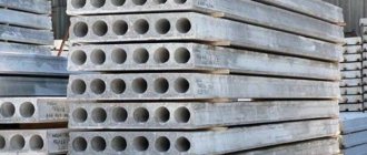
- Concrete wall rings
– made in the format of thin-walled through cylindrical hollow elements, which act as the basis of the structure.
- Well covers
- they are also floor slabs that protect the containers inside from contamination and prevent people from falling into the well. The design of the slab must include a hole for a hatch, which is necessary to provide free access to the inside of the container.
- Bottom plates
– reinforced concrete monolithic slabs that become the bottom of the well and at the same time protect it from groundwater.
- Support rings
– special additional elements designed to form wells of non-standard height (usually used in road construction). The sizes correspond to standard rings, but their height is smaller.
- Base plates
– have a rectangular shape, have an outlet in the middle of a rectangular/round shape, which is then closed with a rectangular grille or a round hatch. Thanks to the shape of the base plate, it is possible to protect the well from possible destruction by distributing the load over the entire perimeter of the element and reducing the load on the walls of the well.
- Sewage wells
– belong to a separate group of products, since these standardized cylindrical structures are used in the installation of underground water/gas supply and sewerage systems. Inside the well there is a metal mesh 0.6-1 millimeter thick.
- Cast iron hatches
– do not relate to reinforced concrete products, but are used in the installation of wells to protect them from unauthorized or accidental entry.
This is what ordinary water supply or sewer wells look like, but other design options can also be used. So, sometimes instead of a bottom, a ring with a bottom is installed or the site is concreted by pouring. If the well is located on the roadway, it is covered not with a lid, but with a rectangular base plate.
Storm drainage systems are often formed using standardized reinforced concrete sewer wells, made in the form of a solid cylindrical block with a bottom, a ready-made hole for a pipe, and reinforced with a metal mesh.
Purpose
Based on the type of systems for the installation of which reinforced concrete wells are used, there are three main types of products.
Types of reinforced concrete wells by type of system:
- Plumbing
– act as elements of heat/water supply, water supply networks, are used for installing valves (shut-off valves) used in regulating the flow of various liquids, measuring valves, fire hydrants, etc.
- Wells for sewerage (treatment, drainage)
– they are needed to create sewer systems in places where pipes change, at bends, etc. Important in the fight against groundwater, which can destroy the foundation.
- Gas pipelines
– used as elements of various types of main gas pipelines.
What types of wells are there by function and purpose:
- Inspection sewer
– are needed where there are turns in pipelines, connections of 2-3 networks, there is a transition from one pipe diameter to another, or simply long sections of the route are marked. Wells are used to perform preventive inspection of pipes and cleaning. Rules for installing wells: pipe diameter up to 30 centimeters - every 35 meters, up to 60 centimeters - every 50 meters, 60-140 centimeters - every 75 meters, if pipes with a diameter of more than 140 centimeters - wells are needed every 150 meters.
- Stormwater
– are needed for collecting and draining rain and melt water from the roadway of sidewalks and streets. In their installation, standardized wells are usually used.
- Septic tanks (cesspools, also known as septic tanks)
– used to clean the sewage system from suspended particles. Installed only in domestic and industrial autonomous systems.
- Chamber wells
– they are installed where the sewerage system intersects with other underground networks. Other lines must be located higher than sewer lines.
- Drop (extinguishing wells)
– they are needed to reduce the speed of water flow in a gravity system. Falling water can produce considerable loads, so the depth of wells is made up to 4 meters. For large-diameter pipelines, several wells are made at once at a distance of 2 meters from each other.
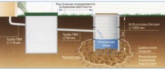
- Filtering (drainage) wells
– designed for wastewater treatment. They do not have a sealed bottom, but there is a drainage base and perforations are made in the walls of the rings.
- Rectangular concrete sewer well
– rare, but used in some systems. The internal volume of such products is used as rationally as possible, but there are certain difficulties in installation, so rectangular structures are used for installing large-diameter pipelines.
For autonomous home systems, pipelines are usually designed with a maximum diameter of 30 centimeters, and wells are made from round rings of a meter in diameter. In a private home, large-diameter rings are used to arrange a mini-pool or cellar.
All standardized and prefabricated products used in the creation of sewer and drainage systems are created in accordance with GOST 8020 from concrete class B15-B22.5, the frost resistance level is at least F150 (the number of freezing/thawing cycles that a reinforced concrete product can withstand without destruction and deterioration of properties) .
What are they used for?
Wells from Rodlex are used to create:
- Drainage, storm, rain sewerage;
- Channels designed for drainage and collection of liquid media;
- Treatment facilities;
- Telephone and telecommunication networks;
- Domestic sewerage.
Wells from Rodlex consist of a tray part, a neck (additional rings) and a lid. All items are purchased separately. Europlast offers components with a diameter of 800 mm. The height is determined by the buyer and can vary due to additional rings.
SNiP requirements for the construction of sewer wells
When choosing reinforced concrete wells and their configuration, the operating conditions and characteristics of the structure being built must be taken into account: for example, for systems located on highways, wells are equipped with rectangular floor slabs with hatches, and for waterproof structures, reinforced concrete rings with a bottom are used.
All reinforced concrete wells are produced according to the requirements of GOST 8020-90, series 3.900.1-14 from heavy concrete of class B15. Concrete from B20 is used for base slabs. The frost resistance of concrete for working chambers of wells is set at a minimum level of F75, for other products - from F100. Water resistance should be at level W6.
Reinforcement of the working chambers of wells is carried out with volumetric reinforcement cages made on special machines. The same frames are used in the reinforcement of round reinforced concrete pipes. In road construction, it is possible to create frames by bending ordinary reinforcing mesh.
The bottom of the wells is reinforced with meshes, which are cut from three-dimensional frames in the areas of the holes. An exception is gas and water wells: their bottoms are reinforced with special reinforcing mesh.
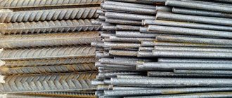
Reinforcing steel of classes and types is suitable for strengthening: wire of class BP-I according to GOST 6727, hot-rolled rod of classes A-I-III according to GOST 5781, thermomechanically strengthened rod of classes At-IIIC/At-IVC according to GOST 10884. All well structures are built according to SNiP 2.04.03.
For manholes
Inspection wells must be installed at the connection points of pipelines, in areas where their direction, diameter, and elevation change. The thinner the pipe, the closer the control points are located. The size of the well in the plan for domestic/industrial sewerage is taken in accordance with the largest diameter.
Pipeline to well diameter ratio:
- If the pipe is less than 60 centimeters, the well should have a diameter of 1 meter.
- Pipe from 60 to 70 centimeters - well 1.25 meters.
- 80-100 centimeters – 1.5 meters.
- 100-120 centimeters – 2 meters.
Features of placement of trays for rotary options:
- For a small diameter pipeline with a laying depth of less than 120 centimeters, wells with a diameter of 70 centimeters can be installed. If the depth reaches 3 meters, the round well must be at least 1.5 meters in size.
- Working height – from the bottom to the support point of the ceiling. For a sewer well it is 180 centimeters. To descend into this part, a stationary or hanging ladder must be mounted (steel brackets are also possible). If the depth is more than 1.5 meters, a fence must be installed.
- The standard well neck is 70 centimeters, but at the turning points (this is where blockages most often occur), the dimensions of the manhole are increased so that the equipment can be lowered for cleaning.
- Hatches should be mounted 5-7 centimeters above the ground for a green area, 20 centimeters higher for an undeveloped area, flush with the soil for a roadway or sidewalk.
- If the bottom of the well is located below the groundwater level, it must be protected from moisture. The walls are also insulated - at least 50 centimeters above the water mark.
For drop wells
Thanks to differential wells, it is possible to reduce the depth of pipes in certain sections of the pipeline, thus reducing the volume of excavation work and reducing the cost of the system. In wells of this type, the flow velocity is dampened, preventing water hammer from occurring in the pipeline.
It is possible not to install a damper well only where the differences are less than 50 centimeters and the pipe diameter is less than 60 centimeters. Here the drainage occurs in the inspection well.
Features of designing drop wells:
- All parameters of the designed differential type wells depend directly on the height of the differential and the diameter of the pipeline. At differences of up to 6 meters, the well is made in the form of a riser with a diameter corresponding to the cross-section of the supply pipe or more.
- A receiving funnel is made above the riser, and in the watering area there is a pit with a base, which is reinforced with a metal plate. For risers with a diameter of up to 30 centimeters, a guide bend is made instead of a pit.
- For storm sewer systems at differences of up to a meter, drainage wells with water gratings/beams are provided (their number depends on the difference in elevations).
Septic tanks and storm water inlets are installed in accordance with individual requirements, which you need to familiarize yourself with before starting the design and implementation of work.
Assembling a well from wall rings
As an example, we took the installation of a well with a diameter of 1 meter and a depth of 3 meters, which is collected in subsidence soils.
Stages of work performed
Before starting work, it is very important to study all the requirements, norms and nuances. After all, the operational characteristics of the structure, the duration and characteristics of its service, and a host of other important factors will directly depend on the correctness of the calculations and design. First you need to calculate everything, decide on a list of necessary materials, think over the order of work, and only then proceed.
Next you need to purchase all the necessary materials. In addition to three KS 10.9 rings, you will need 1 floor, 1 bottom slab, 1 hatch and cement, sand, bitumen-based mastic.
Preparation
Preparing for installation involves the following activities: laying out a site for construction, carefully clearing the area of plants and debris, demolishing interfering structures, laying a temporary ramp or road.
Installation
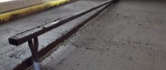
Installation is quite simple: first, a pit is excavated, the bottom is leveled and cleaned, covered with liquid bitumen, and thoroughly compacted. Next, you need to pour a layer of class B3.5 concrete 10 centimeters thick, install trays under the pipes, and reinforce them with steel mesh. The surface of the rings is lubricated with bitumen mastic, a bottom plate is placed on the bottom, and the ring is placed on top.
All joints between the rings must be treated with M50 cement mixture, the surface of the well is plastered from the inside, the soil is backfilled, and waterproof locks are installed at the pipe entries. It is advisable to make a concrete blind area 1.5 meters wide around the neck.
Upon completion of installation, the well must be tested - filled with water for a day to create hydraulic pressure, then visually inspected: if there are no water leaks, the tank has passed the test and the sewerage installation can be considered completed.
Disinfection
Lime bleach for disinfection
After the inside has been cleaned, they proceed to disinfection. For this purpose, bleach is used.
The process is as follows:
- Using bleach, thoroughly wipe the walls.
- They wait for the water to fill up. Then a more caustic compound is added. There are two hundred milligrams of bleach per liter of water.
- Use a sixth to mix the liquid.
- They wait twelve hours. Then add more solution.
- Pumping.
Repeat the process until the water becomes clear/clear.