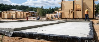
Prices for installing a sand cushion in the estimate are used for many types of construction and installation work. Thus, the prices for the installation of a sand base in the estimate can be used when constructing foundations, installing external utility pipelines, laying asphalt concrete pavements, installing floors, etc.
In addition, the prices in the estimate for dismantling the sand base can also be used when drawing up calculations for various types of construction, installation and repair work and at various objects.
Open gasket
The open method of laying a pipeline cannot be called a popular solution. Rather, it is a compromise when installation using a closed method is not possible.
- preparing and leveling the trench for laying the pipeline;
- strengthening the walls and bottom;
- sand cushion mound;
- pipeline installation;
- covering pipe sections;
- closing the trench;
- leveling the surface and restoring the coating of the object.
The main disadvantage of this method of laying a pipeline is that the pipes are subject to constant mechanical stress (pressure) during periods of ground movement.
What is hidden work
Construction work whose implementation cannot be monitored after other work has been completed is called hidden work. For example: priming the surface before painting, laying pipes and foundations before backfilling, antiseptic treatment and fire retardant treatment of wooden rafters, dismantling work, waterproofing surfaces, installing formwork, laying insulation in multi-layer brick walls, brick walls themselves before plastering - in short, work that cannot be seen eyes after the completion of the construction of the facility (an act was also drawn up for the construction of a driveway surface made of asphalt concrete, since the thickness of the asphalt concrete layer was indicated in the ASSR - the asphalt concrete can be seen with the eyes, but its thickness is not).
Process safety
All organizational measures must be completed.
All excavations must be fenced and equipped with warning signs and, in the dark, with warning lamps.
Transitional bridges or temporary crossings must be built across the trenches in the required places.
To descend into pits and trenches, ladders must be constructed.
It is not allowed to overload the edges of trenches and pits with soil, materials, equipment, because this can lead to the collapse of the soil slope.
It is prohibited for people to be in the area of construction equipment (excavators, bulldozers, rollers, etc.).
When an earthen structure is located near underground communications, before the start of the process, representatives of the owners of communications are called and work on this site is carried out in their presence.
When performing work using special methods: soil development by hydromechanization or explosion; fire, electrical or chemical thawing of frozen soils - measures to ensure the safety of the process are carried out in accordance with the relevant instructions.
Septic tank installation
Installing a septic tank is a rather labor-intensive process that must be carefully planned and can be divided into several stages: choosing an installation location, preparatory work, installing a supply pipeline and septic tank, and installing a drainage system.
When installing local treatment facilities, you should also be guided by SNiP 3.05.04-85* “External networks and structures of water supply and sewerage.”
Choosing an installation location
When choosing a location for a local treatment plant, it is necessary to take into account the requirements of SanPin 2.1.5.980-00 “Hygienic requirements for the protection of surface water” and SNiP 3.05.04-85* “External networks and structures of water supply and sewerage.” Excerpts from the requirements to be taken into account:
- rational use of territory;
- minimum length of communications;
- gravity flow of the main wastewater flow, taking into account pressure losses and using the terrain slope;
- the location of the drainage system relative to the border of the road (5 meters), reservoirs (10-30 meters), a source of drinking water (8-25 meters), trees (3 meters) and a house (5 meters);
- type and composition of soil, height of groundwater.
Installation recommendations:
- If possible, the installation should be located below the level of the house along the natural slope of the area;
- provide for the possibility of access to the installation of a sewage disposal truck for pumping sludge from the septic tank. The optimal distance from the septic tank to the intended access point for the sewage disposal truck is 10-15 meters. Avoid the passage of vehicles over the local treatment facility;
- The septic tank should be located closer to the house. Increasing the length of the route to the installation site makes it more difficult to clean the pipeline in case of blockage and increases the cost of work;
- If possible, the route from the house to the septic tank should be straight and gravity-fed;
- in places where the direction changes and for every 15 meters of the route, it is necessary to provide inspection (drainage) wells;
- All pipes must be connected with sealing rings.
Preparatory work
All sand used when backfilling must be free of large solid inclusions. The compacted sand spills with water.
Preparing the trench
A trench approximately 400 mm wide with a slope of 2% (2 cm per 1 m of pipe) is dug under the pipe leading to the septic tank. The bottom of the trench is leveled with sand, which is carefully compacted.
Preparing a pit for a septic tank
A pit is dug in the location chosen for the septic tank. The width and length of the pit must exceed the dimensions of the septic tank by 500 mm on each side. The minimum depth from the ground level to the septic tank body should be 1.2 m. It is also necessary to take into account the depth of the entrance to the septic tank of the supply pipeline. The bottom of the pit is leveled with a sand cushion (200 mm), which is carefully compacted.
If the groundwater level is high, it is advisable to install a concrete slab equipped with anchor straps at the bottom of the pit. They need to secure the septic tank when installing it. This way the container will be securely fixed.
Preparing a pit for a filtration well
For a filtration well, a hole is dug with a diameter 400 mm larger than the diameter of the well (the larger the hole and the external filter made of sand or crushed stone, the more efficient the system). A cushion of sand or crushed stone 200-300 mm thick is poured into the bottom of the pit.
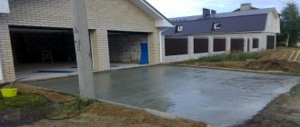
Slab and strip structures
If there is a risk of subsidence, the “floating” slab technology is also used. Such a foundation is a monolithic reinforced concrete slab 0.4-0.6 m thick. It is located under the entire area of the house, which helps distribute the load on the foundation more evenly. When subsidence or heaving occurs, the slab retains its integrity and protects the building structure from destruction. The main disadvantage is the high price of the solution.
When using strip foundations, uneven settlement is limited in different ways. One option is to use intersecting tapes. For rigidity, the foundation is reinforced with reinforced frames and belts: one belt in the tape cushion, and the second on top of the foundation. An option is to increase the area of support of the structure on the base.
Determining factors
In order to find out at what depth to lay the sewer, you need to take into account several points that affect this value.
Factors influencing the level of pipe laying:
- mark of soil freezing in a given climate zone;
- outer pipeline diameter;
- materials from which parts of the structure are made;
- the topography of the area along which the system is installed;
- the distance from the mark of the sewerage entrance to the septic tank to the surface of the earth.
Attention! Before starting work on laying sewer pipes in a private house, it is recommended to draw a diagram of the external and internal sections of the sewer system, indicating the level of laying the sewer pipes.
The layout of the external site should be carried out taking into account the location of trees, buildings, and site boundaries. Also in the picture you need to indicate the water supply. SNiP provides for minimum distances from these objects to the septic tank.
External sewerage scheme
Stroy-Tekhnika.ru
Construction machines and equipment, reference book
Pue 7. rules for electrical installations. edition 7
TO
category:
Excavator operation
P
publication:
General concepts about earthworks
H
read more:
Basic information about excavator faces and soil development
General concepts about earthworks
Earthworks are a group of engineering structures formed in a soil mass or erected from soil laid on the surface of the earth.
An earthen structure is called an excavation if it is located below the surface, and an embankment if it is built on the surface of the earth. If the earthen structure is located on a slope, then it may consist partly of excavations and partly of embankments. In cross-section, the structure in these cases is designed in the form of a half-cut and half-embankment.
Promotional offers based on your interests:
Rice. 1. Scheme of hydraulic engineering earthworks: a - dam, b - channel in the excavation, c - channel in the half-embankment-half-excavation, d - channel in the embankment
According to their purpose, earthen structures are divided into hydraulic structures (dams, dikes, canals, port buckets, embankments); reclamation (ponds, water retention structures, water supply, distribution and drainage canals, treatment facilities, etc.); road (roadbed for railways and highways); industrial and civil construction structures (industrial enterprise sites, water supply and sewerage structures), etc.
Hydraulic earthworks. The main types of these structures are dams (dams) and canals. In Fig. 279, and shows a schematic section of the dam. The crest of a dam is its upper platform, at least 2-3 m wide, rising 1-2 m above the highest water level. The lock, or tooth of the dam, is a depression located in the middle
Rice. 2. Diagram of the road subgrade: a - railway bed on an embankment, b - railway bed in a excavation, c - railway bed in a half-cut-half-embankment, d - road bed
the foundation of the dam and filled with soil from which the dam is built. The tooth is designed to better connect the dam body with the bottom of the reservoir. A wet slope is the side surface of the dam on the water side, and a dry slope is the opposite surface.
A channel is a longitudinal depression filled with water. According to their purpose, canals are navigable, irrigation and drainage.
Channels may be in cut-outs, half-fill-half-cuts or in embankments.
Road structures. An earthen structure formed by soil poured over the natural surface of the earth and used to lay a road along it is called a road embankment. A road excavation is an earthen structure formed by excavating soil below the surface of the earth.
The earthen base of a road, formed by embankments and excavations, is called a subgrade. The roadbed can be built on a slope and consist of a half-cut and half-embankment.
To protect roadway excavations from the influx of surface water, ditches (ditches) are installed on both sides, through which water flowing from the slopes is drained away from the roadbed. On the upper side of the excavation, a mountain ditch is arranged to drain rain and melt water flowing from the slopes of the area.
Trackless roads are constructed according to standard transverse profiles of the roadbed (Fig. 280, d). The top of the canvas for rainwater drainage is made with a slope towards the edges of the slope. In the middle part of the roadbed, soil is removed (the so-called trough) for laying the road surface. On both sides of the trough there are two stripes, called curbs.
Pits and trenches. An open development intended for the construction of an underground part of a structure (foundation, etc.) is called a pit. After the foundations are erected, the space between it and the walls of the pit is filled up. This operation is called backfilling.
For safe work in the pit during the construction of foundations, the walls of the pit slopes are made flat. For different soils, the steepness of the slopes is assumed to be different.
A trench is an open excavation that has a considerable length and a relatively small width. The trench is intended for laying various linear structures in it (water supply, sewerage, electrical cables, etc.).
Promotional offers:
Read more: Basic information about excavator faces and soil development
TO
Category: — Operation of excavators
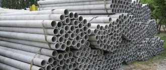
Mechanical protection of pipelines
PENOPLEX® segments can perform not only the function of insulation, but also protect pipes from damage. Due to their strength and reliability, they create a hard outer shell that helps maintain the integrity of the internal waterproofing of the pipeline. Such protection makes it possible to lay communications even in difficult conditions - in rocky and limestone formations, as well as in areas with a high risk of earthquakes. A good example is the construction of the Blue Stream gas pipeline, where extruded polystyrene foam segments were used to protect pipes in earthquake-prone areas.
Overhead installation
Conditions in which above-ground pipeline installation is justified and effective:
- in an area with heavily icy soils (or underground ice);
- on rough terrain (reservoirs, ravines, residential and industrial facilities, other obstacles along the route that only an overhead installation can overcome);
- high activity of cryogenic processes in the region.
For above-ground installation, pipes made of cold-resistant steel with mandatory insulation are used. For the reliability and safety of the system, it is reinforced with reinforced concrete supports.
Compared to the underground method, above-ground installation ensures high-quality drainage of water (surface), eliminates damage to the environment, damage to soil layers, and simplifies the maintenance of highways. But above-ground installation is not popular due to the cost of construction and maintenance. Pipeline laying work requires extensive experience and highly qualified performers. Added to this is the consumption of expensive materials and strict requirements for calculations.
Underground laying of pipelines.
When installing heating pipelines underground, two methods can be used:
- Direct laying of pipes in the ground (channelless).
- Laying pipes in channels (channel).
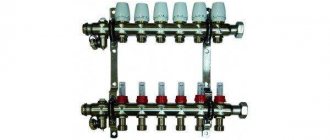
Laying pipelines in channels.
In order to protect the heat pipeline from external influences and to ensure free thermal elongation of the pipes, channels are designed. Depending on the number of heat pipes laid in one direction, non-through, semi-through or through channels are used.
To secure the pipeline, as well as to ensure free movement during thermal expansion, the pipes are laid on supports. To ensure the outflow of water, the trays are laid with a slope of at least 0.002. Water from the lower points of the trays is removed by gravity into the drainage system or from special pits using a pump it is pumped into the sewer system.
Blasting technology
Ejection explosions are used to construct pits and trenches. If the width is small, the charges are arranged in one row (along the length), and detonation is carried out with a fire cord. If the width is large, 2...3 rows of charges are used with simultaneous detonation of them with a detonating cord or electrically (Fig. 2.13, c). If the width of the earthen structure is very large, it is divided into sections.
To build embankments in hard-to-reach places (and swampy or mountainous areas), directed ejection (one of the types of directional explosions) is used. Explosive charges of different types and weights are arranged in such a way that when they are fired sequentially (with a given deceleration), the bulk of the developed soil, up to 80–90%, is placed in the design location (Fig. 2.14, d). The charges are detonated using electric detonators, and detonators with a delay (25–250 milliseconds) are used for guiding charges.
To loosen dense and strong soils at excavation depths of up to 3.0 m, the method of blast-hole charges is used (Fig. 2.14, b); for excavation depths of 3.0...5.0 m, the method of small-chamber charges is used.
Closed cavities in soils of groups I–III are arranged for the widened part of camouflage piles of varying load-bearing capacity (Fig. 2.14, c).
Advantages of the method: high efficiency - enormous productivity; work with any soil (groups I–XII); low cost of explosives and the work themselves; uniqueness of the product - camouflage, directed ejection.
Disadvantages: high danger; work may only be carried out by specialized organizations; low accuracy (needs improvement); large dynamic impacts on the environment.
| Rice. 2.14. Explosive means: a – ejection; b – for crushing; c - camouflage; d – directional: 1 – working concentrated charges; 2 – hole (extended) guide charges; 3 – design pit; 4 – position of the ground at the moment the guide charge is triggered |