Monolithic reinforced concrete structures were first used in Russia in 1802. Metal rods were used as reinforcement material. The first building created using this technology was the Tsarskoye Selo Palace.
Monolithic reinforced concrete structures are often used in the production of products such as:
- tanks,
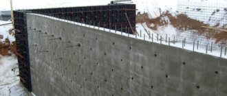
- walls,
- floors,
- foundations.
Reinforced concrete monolithic structures allow the construction of buildings of any complexity and configuration. In addition, this technology is not limited to factory standards. The designer has an incredibly wide field for creativity.
Calculation of slab thickness
The calculation is carried out according to the joint venture “Design and installation of foundations and foundations of buildings and structures” and according to the manual “Guidelines for the design of slab foundations of frame buildings and tower-type structures” in two stages:
- load collection;
- calculation based on bearing capacity.
Collection of loads includes work to calculate the total mass of the house, taking into account the weight of snow cover, furniture, equipment and people. Values for houses made of various materials can be taken from the table.
| Load type | Meaning | Reliability factor |
| Walls and partitions | ||
| Brick 640 mm | 1150 kg/m2 | 1,2 |
| Brick 510 mm | 920 kg/m2 | |
| Brick 380 mm with insulation 150 mm | 690 kg/m2 | |
| Beam 200 mm | 160 kg/m2 | 1,1 |
| Beam 150 mm | 120 kg/m2 | |
| Frame 150 mm with insulation | 50 kg/m2 | |
| Plasterboard partitions 80 mm | 30-35 kg/m2 | 1,2 |
| Brick partitions 120 mm | 220 kg/m2 | |
| Floors | ||
| Reinforced concrete 220 mm with cement-sand screed 30 mm | 625 kg/m2 | 1.2 - for prefabricated and 1.3 - for monolith |
| Wooden on beams | 150 kg/m2 | 1,1 |
| Roof on wooden rafters | ||
| Metal coated | 60 kg/m2 | 1,1 |
| Ceramic coated | 120 kg/m2 | |
| With bitumen coating | 70 kg/m2 | |
| Live loads | ||
| Useful for residential buildings | 150 kg/m2 | 1,2 |
| Snow | Depending on the construction area according to clause 10.1 of the SP “Loads and Impacts”. The snow region is determined by the SP “construction climatology”. | 1,4 |
Important! The table already takes into account the thickness of the structures. To calculate the mass, all you have to do is multiply by the area
In addition, each load must be multiplied by a safety factor. It is necessary to ensure a reserve for the load-bearing capacity of a concrete structure and to prevent problems in the event of minor errors by builders or changes in operating conditions (for example, a change in the purpose of the building). All coefficients are accepted according to the joint venture “Loads and Impacts”.
For different loads, the coefficient is different and ranges from 1.05-1.4. The exact values are also given in the table. For a concrete foundation using monolithic technology, a coefficient of 1.3 is taken.
Important! If the roof slope is more than 60 degrees, the snow load is not taken into account in the calculation, since with such a steep slope, snow does not accumulate on it. The total area of all structures is multiplied by the mass given in the table and the coefficient, after which, adding, the total weight of the house is obtained without taking into account the foundations
The total area of all structures is multiplied by the mass given in the table and the coefficient, after which, adding, the total weight of the house is obtained without taking into account the foundations.
The basic formula for calculations is as follows:
P1= M1/S,
where P1 is the specific load on the ground without taking into account the foundation, M1 is the total load from the house obtained when collecting loads, S is the area of the concrete slab.
Next, you need to calculate the difference (Δ) between the obtained value and the number given in the table above, depending on the type of soil.
Δ=P-P1
where P is the tabulated value of the bearing capacity of the soil.
M2 = Δ*S,
where M2 is the required mass of the foundation (it is impossible to build a foundation greater than this mass), S is the area of the concrete slab.
The following formula:
t = (M2/2500)/S,
where t is the thickness of concrete pouring, and 2500 kg/m3 is the density of one cubic meter of reinforced concrete foundation.
Next, the thickness is rounded to the nearest larger and smaller multiple of 5 cm. Afterwards, a check is performed in which the difference between the calculated and optimal pressure on the ground should not exceed 25% in any direction.
Advice! If the calculation turns out that the thickness of the concrete layer exceeds 350 mm, it is recommended to consider such types of construction as a strip foundation, columnar or slab with stiffeners.
In addition to the thickness, you will need to select the appropriate reinforcement diameter, as well as calculate the amount of reinforcement for concrete.
Important! If, as a result of the calculation, you get a slab thickness of more than 35 cm, this indicates that the slab foundation is redundant in the given conditions, you need to calculate strip and pile foundations, perhaps they will be cheaper. If the thickness is less than 15 cm, then the building is too heavy for the given soil and accurate calculations and geological studies are needed
Important Installation Conditions
As a rule, reinforcement occurs in removable formwork, where a steel frame is installed, after which it is filled with concrete mortar no lower than M250.
In order for the monolithic floor slab to receive all the necessary strength characteristics, the developer must strictly comply with the requirements of the regulations and the conditions of the project :
- Longitudinal rods are selected depending on the size of the slab and its load-bearing capacity in the range of 8 - 14 mm, and transverse rods - 6-10 mm.
- The thickness of the structure is determined by the span length and compliance with the regulatory requirement of 1/30, but not lower than 150 mm. For spans longer than 8 m, a stressed mesh of increased strength reinforcement is used.
- Single-layer reinforcement is performed for slabs with a thickness of 150 mm, and two-layer reinforcement for slabs with a thickness of over 150 mm.
- Additional reinforcement is performed in the center of the ceiling, in the areas of technological holes and support.
- It is allowed to use stressed hot-rolled ribbed reinforcement of class not lower than AIII.
- The first mesh is installed at the bottom of the formwork, and the second at the top. In the mesh, the reinforcement is tied with a special soft annealed knitting wire to create cells of 150x150mm or 200x200mm.
- The location of the mesh inside the monolithic structure is protected by a thickness of concrete on all sides of 25-30 mm.
- The overlap of the rods when connecting depends on the diameter and is equal to 10 D, while the minimum overlap should not be less than 50 cm and be staggered in relation to adjacent connections.
- At the edges the mesh is connected in a U-shaped configuration.
- Reinforcement is bent only as a last resort without heating, since high temperature damages the internal structure and leads to a fracture of the rod.
Important! Places of reinforcement are made only according to the design drawing, with reinforcement of the indicated diameter. Because excess metal leads to an increase in the load on the slab, which may exceed its design limits.
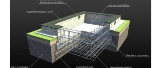
Construction of a slab foundation with your own hands.
First you need to prepare the site; this is perhaps the most labor-intensive operation in the construction of a slab foundation. To do this, the top layer of soil is completely removed to a depth determined by calculation. It is recommended to remove and level the last layer manually; this is done in order to avoid unevenness and holes. The pit itself must exceed the dimensions of the foundation by 1-2 m on all sides for ease of work.
Preparing a cushion for a slab foundation made of sand and gravel. Such a cushion is necessary to compensate for the forces of soil deformation, as well as to drain groundwater and prevent its capillary rise to the base of the foundation. The thickness of the cushion depends on the type of soil: on sandy soils it can be 15 centimeters, on saturated clay soils or prone to severe heaving - at least 30 centimeters. Sand is poured into the pit, evenly and distributed over the entire area of the foundation, after which it is thoroughly compacted. For swampy or wet types of soil, part of the cushion will consist of crushed stone, this improves the waterproofing of concrete.
Construction of formwork for a slab foundation. The formwork for a slab foundation must consist of planed boards with a thickness of at least 20 mm, which are connected at the corners using self-tapping screws. From the outside, the formwork is strengthened with struts. Sometimes permanent formwork made of fiberboard is used for slab foundations. It is attached to metal corners and ties, and then struts are also arranged. After the work described above, it is necessary to construct penetrations for communications, and at the same time install formwork around them. Pipes can also be laid and routed through penetrations before the foundation is poured.
Waterproofing of a slab foundation is carried out using a thick polyethylene film, geotextile or roofing felt; it is laid overlapping on the bottom of the pit with an approach to the formwork.
Reinforcement of a slab foundation is a very important stage; the strength of not only the foundation itself, but also the building as a whole will depend on it. For small structures, reinforcement can be done using reinforcing mesh with a mesh size of 10-15 centimeters, and the places where load-bearing walls will be installed must be reinforced with metal rods. If the structure of the structure is more massive, for reinforcement it is necessary to use a rod with a diameter of 10-12 mm, laid in the form of a mesh. The transverse rods are knitted together using wire. Welding of reinforcement is rarely used, since excessive stresses arise at the welding points when the structure moves. The reinforcing mesh must be completely immersed in concrete; for this it is installed on special guides. If the thickness of the foundation is large, then several layers of reinforcement are installed.
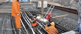
Pouring concrete for a slab foundation is done simultaneously, so you will either have to order concrete or mix it very quickly with your own hands. Therefore, pouring must be done by a team of 4-5 people. Concrete is poured into prepared formwork with laid reinforcement, after which it is compacted first using an internal vibrator, and then using a vibrating lath. After punching the concrete and removing voids and air from it, it is smoothed and the surface is leveled.
Drying of the slab foundation occurs within 4-5 weeks. During this time, the concrete gains the necessary strength, after which it is ready for further use. During drying, you need to carefully monitor that the top layer of the foundation does not dry out and is not exposed to excessive moisture; for this, you can use a material with which the concrete can be covered. After the concrete has dried, to improve the thermal insulation properties, the slab foundation can be insulated using polystyrene slabs.
Calculation of strip and column foundations
Reinforcement of a strip foundation, calculation of reinforcement, laying and tying are carried out, in principle, in the same way. You just need to take into account that the reinforcement grids in this design are installed not horizontally, but vertically. In this case, the length of the longitudinal rods depends on the length of the tape, and the transverse rods on the depth of the foundation.
The width of the tape determines the number of grids and the length of the rods connecting the grids together. For example, if the width of the foundation strip is 40 cm, then a distance of 25 - 30 cm is left between the gratings, this is the length of the connecting rods.
As for the quantity, again, everything will depend on the size of the cells of the reinforced foundation belt. For example, if the laying depth is 1 m, and the frame is laid inside the concrete mass, then the distance from the upper surfaces is set to 10 cm on each side. Therefore, the length of the transverse rods will be 80 cm. And the number of longitudinal guides will be equal to 100/20 = 5 rows.
The rules for reinforcing columnar structures are very different from the two previous options. Firstly, these are vertically installed rods, tied with wire rod with a diameter of 6 mm or small reinforcement. It all depends on the size of the support pillars themselves. Secondly, the cross-section of the frame is either a square, a circle, or a triangle.
The length of the main rods depends on the depth of the foundation. In this case, there is no need to take into account the distance from the bottom of the well to the reinforcement, because the finished reinforcing structure is installed directly on the prepared pad. But you will have to take into account the protrusion of the rods in the amount of 10 - 70 cm, which will stick out from the pillars. They will be connected to the grillage reinforcing mesh.
Which fittings are suitable?
Steel and composite fiberglass reinforcement are used to reinforce monolithic slabs. The most widely used steel reinforcement today is A500C , according to the modern designation S500, popular diameters for longitudinal bars are 10 and 14 mm, and for transverse ones 6-8 mm.
For key reinforcement of a monolithic structure, a corrugated reinforcing rod is always used in order to create the strongest connection with the concrete.
Corrugated reinforcing rod:
To make additional components that do not have a great impact on the load-bearing capacity of the monolithic slab, it is allowed to use smooth A1 reinforcement.
Smooth reinforcement A1:
Composite reinforcement is an innovative building material that reduces costs during the construction of facilities. Such fittings are especially popular in the USA and EU countries.
Composite reinforcement:
Advantages of using composite reinforcement:
- Cheaper by 30 percent or more than steel reinforcement of the corresponding diameter.
- It is several times lighter, therefore, the cost of 1 m2 of such a monolithic structure becomes lower due to the reduction in transportation costs, the weight load on the walls and foundation is also reduced, while maintaining higher strength indicators.
- More reliable in operation since anti-corrosion protection is not required.
- More environmentally friendly.
- Thermal conductivity is 100 times less than that of steel.
- High durability, increases the service life of the slab up to 100 years.
- Wide range of diameters of fiberglass reinforcement from 6 to 20 mm.
In modern individual house construction, when creating monolithic structures, they practice the simultaneous use of metal and fiberglass reinforcement.
Material requirements
All fittings that are supposed to be laid in a monolithic slab must comply with the project for the house and be purchased with certificates guaranteeing its quality and compliance with the standard.
Requirements for reinforcement products for forming a monolithic floor slab:
- should not be subject to delamination;
- its surface should not contain any defects in the form of shells;
- it must fully comply in appearance and dimensions with the manufacturer’s brand and design specifications;
- it must be tested for deformability; the reinforcement is considered suitable if no cracks occur when it is bent 180 degrees in a cold state.
Attention! The reinforcement for the manufacture of reinforced concrete floor slabs is assumed to be prestressed; for certain types of structures, GOST establishes exceptions.
Calculation of reinforcement diameter
Calculations associated with a monolithic slab are quite complex and require special knowledge. Not every designer can implement them correctly. For individual construction, you can be guided by the minimum values accepted according to the manual “Reinforcement of elements of monolithic reinforced concrete buildings”.
The requirements for a monolithic slab are presented in Appendix 1, section 1. The total cross-sectional area of the working reinforcement in one direction is taken to be at least 0.3% of the total cross-section of the foundation. The minimum diameter of the rods is 10 mm for a side of the slab less than 3 m and 12 mm for a longer side length. The diameter of the vertical rods must be at least 6 mm, but weldability conditions must also be taken into account. The maximum size of working reinforcement is 40 mm; in practice, 12, 14 and 16 mm are more often used.
Calculation example
The initial data is a reinforced concrete slab 6 by 6 m. The thickness for a private house is assumed to be 200 mm. It is necessary to properly reinforce the structure. The example does not consider the reinforcement of reinforced concrete in the areas where the walls support.
Determination of diameters
First of all, it is determined that the grids will be laid in two rows, since the thickness of the structure is more than 150 mm. Next, the required area of steel rods is calculated.
- Cross-sectional area of the foundation = 6 m * 0.2 m = 1.2 m²;
- Minimum area of all reinforcement = 1.2 m² * 0.3% = 0.0036 m² = 36 cm²;
- Minimum reinforcement area in one direction for one row = 36 cm²/2 = 18 cm².
Next, you need to use the assortment of reinforcing bars, which is given in GOST 5781-82*. This document shows the cross-sectional area of one rod. For convenience, you can find an expanded version of the assortment. It determines that for a given section in one grid it is necessary to use one of the following options:
- 16 rods with a diameter of 12 mm;
- 12 rods with a diameter of 14 mm;
- 9 rods with a diameter of 16 mm;
- 8 rods with a diameter of 18 mm;
- 6 rods with a diameter of 20 mm.
We choose the option with a twelfth diameter. To correctly arrange the elements you need a diagram. The drawing will help you calculate the pitch of the rods. For a side 6 m long, the pitch of 16 rods is approximately 400 mm. We assign a maximum distance of 300 mm based on the conditions of SP 63.13330.2012 clause 10.3.8.
For reliability, vertical reinforcement is 8 mm in increments of 300 mm.
Quantity calculation
We recently launched a slab foundation calculator, you can use it for convenience.
In order not to make mistakes when purchasing materials, it is necessary to calculate their quantity in advance. If you have a diagram of the stove, this is not difficult to do. When calculating the lengths of the rods, it is necessary to take into account the thickness of the protective layer of concrete 20-30 mm on each side.
Calculation of working reinforcement.
- Length of one rod = 6000 - 30*2 = 5940 mm;
- Number of rods in one direction = 5940/300 = 19.8, take 20 pcs;
- Number of rods in both directions for the upper and lower mesh = 20*2*2 = 80 pcs;
- Length of one rod for U-shaped clamps = 200 mm + (200 mm * 2)*2 = 1 m;
- Number of rods for U-shaped clamps = 20*2 = 40 pcs;
- Total length of reinforcement with a diameter of 12 mm = 80*5.94 m +40*1 m = 515.2 m;
- Mass of rods with a diameter of 12 mm = 515.2 * 0.888 kg (located according to the assortment) = 457.5 kg.
Calculation of vertical reinforcement.
- Length of one rod = 200 - 20*2 = 140 mm;
- Number of rods = number of horizontal rods in one direction * number of rods in the other = 20 * 20 = 400 pcs;
- Total length of rods with a diameter of 8 mm = 400 * 0.14 = 56 m;
- Mass of rods with a diameter of 8 mm = 56 * 0.395 = 22.12 kg.
It is convenient to summarize all the resulting values in a table.
| Diameter | Length | Weight |
| 12 mm | 515.2 m | 457.5 kg |
| 8 mm | 56 m | 22.12 kg |
When calculating costs, it is worth taking into account the standard length of one rod - 11.7 m, this means that, for example, 5-6 rods of 8 diameters will be needed with a small margin. And with a large length of working reinforcement, it is necessary to increase the total length by 10-15% to connect the rods with an overlap.
A competent choice of diameter, pitch and adherence to installation technology will ensure the reliability and durability of the foundation at the lowest possible cost.
We recommend: Slab foundation construction technology.
Good publicity
Reinforcement of reinforced concrete structures
Concrete has a significant disadvantage inherent in all stone materials of artificial and natural origin: it works well in compression, but does not resist bending and stretching well. The tensile strength of concrete is only 7...10% of its compressive strength. To increase the tensile and flexural strength of concrete, steel wires or rods called rebar are placed in it. Armature from Latin means “weapon.” Concrete, armed with reinforcement, is capable of much.
A little history
Cement was invented in 1824 - 1825. almost simultaneously, independently of each other, Egor Cheliev in Russia and Joseph Aspdin in England. The production of cement and the use of concrete were rapidly improved and developed, but a significant drawback remained - the poor tensile strength of concrete.
The discovery of reinforced concrete belongs to the Parisian gardener Joseph Monier, who decided to make concrete flower pots instead of wooden ones. For strength, he laid wire in the concrete. The resulting products are very durable. This is how reinforced concrete appeared (patented in 1867), in which concrete and steel complemented each other. The metal prevented tensile cracks from occurring, and the concrete protected the steel from corrosion. Attempts to create reinforced concrete had been made before (1845 - W. Wilkinson, England; 1849 - G.E. Pauker, Russia). The first reinforced concrete structures appeared in 1885.
Reinforced concrete is not two dissimilar materials (concrete and steel), but a new material in which steel and concrete work together, helping each other. This is due to the following reasons.
The adhesion strength of the reinforcement to the concrete is quite high. So, to pull out a rod with a diameter of 12 mm from concrete, inserted to a depth of 300 mm, a force of at least 400 kg will be required. The adhesion of steel to concrete is not disrupted even with strong temperature changes, since their coefficients of thermal expansion are almost the same.
The modulus of elasticity of steel is almost 10 times higher than that of concrete. That is, when concrete and steel work together, the stresses of steel are 10 times higher than those of concrete, which leads to a redistribution of loads acting in the tensile zone of the beams. The main load in the tension zone of the beam is borne by steel, and in the compressed zone - by concrete.
Concrete, due to its density and water resistance, on the one hand, and the alkaline reaction of cement stone, on the other, protects steel from corrosion (passivation).
In addition, concrete, as a relatively poor conductor of heat, protects steel from extreme heat during fires. At a concrete surface temperature of 1000°C, the reinforcement located at a depth of 50 mm will only heat up to 500°C after 2 hours.
When a reinforced concrete structure is subjected to bending at maximum load values, cracks with a thickness of less than 0.1...0.2 mm (so-called hairline cracks) may appear in the tensile zone of concrete, which are not dangerous from the point of view of adhesion of the reinforcement to the concrete and metal corrosion.
In order for the reinforcement to be quickly included in the work of concrete, it is produced with a relief surface, equipped with notches of various configurations. A reinforced concrete structure will perform better if the main strength bars of the reinforcement cage are connected into a single welded structure with cross bracing.
The purpose of reinforcement can be explained using reinforced concrete products working in bending, which are widely used in construction practice. Beams over openings of windows and doors, reinforced concrete panels and floor slabs, beams and crossbars of bridges and workshop buildings can be classified in this category of construction products.
A little "compromise"
“Sopromat” – strength of materials – the science of structural strength. Any structure that is subject to forces experiences internal stresses corresponding to the magnitude and direction of action of these forces. The task of designers is to create a structure in which the level of internal stresses will not be higher than those that the materials used can withstand, and the deformations of the structure will not exceed the permissible value.
If we take a concrete beam loaded with any forces, for example, a distributed load (q) (Figure 114, a), then two types of stress are simultaneously acting in it: normal (a) and shear (t). It should be noted that the magnitude of these stresses varies not only along the length of the beam, but also along the height of its cross section.
But the length of the beam, in each of its cross sections, the state of stress from the influence of external loads can be equated to the simultaneous action of two loads - bending moment (M bend) and shearing force (Q), the magnitude of which in each section of the beam is calculated using certain formulas of "strength strength" "
The largest bending moment will be in the middle of the beam. Towards the ends it will decrease to zero. A graphical representation of such a change is called a diagram of bending moments M bend (Figure 114, c).
The diagram of shear forces Q (Figure 114, d) shows that their greatest value falls precisely on the supports on which the beam rests.
Figure 114. Beam under load “P” and stresses in it: A – unreinforced beam; B – reinforced beam; B – diagram of bending moments; G – diagram of shearing forces; 1 – concrete beam; 2 – fittings; 3 – crack from beam bending; 4 – crack due to shearing force; 5 – compression stress; 6 – tensile stress
What happens to such a beam?
Due to the action of the bending moment, normal stresses arise in it (compression-tension), which vary along the height of the section from the greatest compression at the top to the greatest tension at the bottom. In the neutral middle zone of the cross section, normal stresses are zero. The greatest stresses from the bending moment will be in the middle of the span. If the concrete is “not armed” with reinforcement, then cracks may appear below, in the zone of tensile stress (Figure 114, a).
In the zone of maximum shearing forces, the greatest tangential stresses arise. We draw the attention of lovers of “strengthening materials” to the fact that tangential stresses create a stressed state in the body of the beam, which is characterized by the simultaneous action of normal compressive and tensile stresses, oriented to the horizontal at an angle of 45°. The tensile component of stress in the support area can provoke the appearance of inclined cracks (Figure 114, a).
Reinforcing the beam with steel rods, which strengthen the concrete mass in the zone of greatest tensile stress in the middle of the span and near the supports, allows you to create a rigid and strong reinforced concrete structure (Figure 114, b).
Attention!
Tensile stresses in beams near the supports can cause the occurrence of inclined cracks only with a relatively large distance between the supports and a small thickness of the beam (floor slabs, long over-window lintels, beams or crossbars of bridges, etc.). Therefore, when reinforcing foundation strips or house walls, inclined bends of reinforcement in the support area can be omitted.
Where is the best place to place the fittings?
The greatest efficiency of reinforcement under bending loads is created when it is located in the zone of maximum deformations from tensile stresses, as close as possible to the edge. But concrete must protect the reinforcement from corrosion, and the compression of the reinforcement with concrete must be complete on all sides. Therefore, the reinforcement is placed in the concrete mass no closer than 3...5 cm from the surface of the reinforced concrete product, and the denser the concrete, the smaller this distance can be.
Stressed concrete
The use of high-strength rods as reinforcement does not fully realize their potential. When they are fully loaded by tension, relatively wide cracks appear in the concrete mass, reducing the corrosion resistance of the reinforcement. To increase the efficiency of its operation, the process of concreting and maturing of concrete occurs with tensioned reinforcement. This creates stressed concrete that is in a compressed state and in the absence of loads.
The use of the pre-tensioning method makes it possible to increase the efficiency of the reinforcement and the entire reinforced concrete structure. In the thickness of concrete, tensioned reinforcement creates compressive stresses, which, when added to the bending stresses acting on the structure, form a relatively small component of tensile stresses (Figure 115, a).
Figure 115. Examples of stressed concrete: A – beam; B – Ostankino TV tower; 1 – concrete base of the TV tower; 2 – tension cable; 3 – stress from weight; 4 – tension from cable tension; 5 – bending stress; 6 – total stress in the cross section; 7 – concrete; 8 – shape; 9 – reinforcement in a stretched state; 10 – reinforced concrete beam under load
This is interesting
The Ostankino TV tower in Moscow was built in the early 70s of the last century. The tower pierces the Moscow sky like a thin needle, striking the imagination. You can’t help but wonder: how does such a thin structure withstand wind loads? The main part of the television tower is made in the form of a pipe of variable cross-section, cast from high-strength reinforced concrete. Powerful cables are stretched inside the pipe, loading the concrete mass with compression and eliminating the appearance of tensile stresses in the concrete when the tower bends from wind loads (Figure 115, b). Specialists carefully monitor the tension of the cables.
Prestressed concrete structures utilize the strength of steel and concrete more fully, thereby reducing the weight of the products. In addition, pre-compression of concrete, preventing the formation of cracks, increases its durability. Railway sleepers made using this technology have a very long service life when used in the most severe climatic conditions.
Armature
Reinforcing bars and welded reinforcing mesh are used in the production of reinforced concrete products at reinforced concrete factories and for concreting carried out directly on the construction site (foundation construction, wall reinforcement, creation of concrete floors and window lintels, concreting roads and blind areas...).
Depending on the mechanical properties and manufacturing technology, the reinforcement is divided into classes and designated by the following letters: A - rod reinforcement; B – wire; K - ropes.
To ensure maximum savings, it is advisable to use reinforcement with the highest mechanical properties.
The industrialization of reinforcement works is successfully achieved through the widespread use of welded mesh, flat and volumetric welded frames.
The metallurgical industry produces reinforcement bars with a diameter of 5.5 to 40 mm. It should be taken into account that the use of large diameter reinforcement (more than 12 mm) in individual construction conditions cannot be considered justified. Large cross-sections of reinforcement are used for large spans of beams, which are found only in industrial construction. This limitation is due to the fact that the reinforcement during the operation of a concrete structure is loaded with tensile stresses. Reinforcement of large sections with small dimensions of buildings does not have time to be fully loaded, which is why the full collaboration of concrete and reinforcement does not occur. The optimal diameter of rods in individual construction conditions is 6...12 mm (reinforcement of foundations and walls, creation of a seismic belt).
When planning to join reinforcement bars, individual developers do not always want to get involved with welding work. A simple overlap of reinforcement over a length greater than 60 rod diameters is a sufficient condition for their connection. For example, with a rod diameter of 12 mm, the overlap of the rods should be at least 72 cm. If the ends of the rods are bent, the length of the overlap can be reduced by two to three times.
Quite often, developers use the metal they have or the one their friends offer them to reinforce concrete structures.
Yes, metal is now expensive and this approach to the selection of fittings is quite understandable. But there are some limitations to this.
What cannot be used for reinforcement:
– aluminum rods (low modulus of elasticity and lack of adhesion to concrete); – sheet strip steel (provokes the appearance of cracks in the plane of the sheet material with a relatively small cross-sectional area, weak adhesion of the metal to the concrete along the plane); – strips of sheet material with perforations – waste from stamping production (very small actual cross-section of the reinforcement); – chain-link mesh (having the properties of a spring, it cannot play a reinforcing role); – pipes remaining after the dismantling of gas pipelines, water supply systems or central heating (water can accumulate in the cavity of the pipes, which, when frozen, will destroy the pipe and concrete); – massive profiles in the form of angles, channels, I-beams or rails (the large cross-sectional area and relatively weak adhesion of concrete to flat sections of metal make it difficult to incorporate metal into the work and interfere with the creation of a unified structure of reinforced concrete); – reinforcement bars less than 1 m long (they do not have time to start working).
If the reinforcement is covered with paint, grease or oil films, all this must be removed to ensure good adhesion of the metal to the concrete.
Recently, products made of fiberglass and plastic with basalt fibers have begun to be used as reinforcement in reinforced concrete structures.
Reinforcing mesh made of glass fibers, impregnated with bitumen, is used for reinforcing asphalt concrete pavements and roads, airfield pavements, as well as during road repair and restoration work. Produced according to TU 2296-041-00204949-95. In TISE technology, it is used to reinforce walls.
The tape is produced in rolls (75-80 m) 1 m wide. Cell – 25×25 mm. Tensile strength – 4 tons per meter of width. The mesh is easy to transport and cut (can be cut with ordinary scissors), does not create “cold bridges”, does not rust, and is inert to electromagnetic radiation.
Flexible ties made of basalt fibers - rods with a diameter of 5...8 mm with curved ends. The length of the flexible connection is agreed with the manufacturer. A strong and rigid flexible connection is not subject to corrosion, stands well in concrete, and does not create a “cold bridge”. In TISE technology, it is used in the construction of three-layer walls without “cold bridges”.
Replacing metal wall reinforcement with non-metallic makes it possible to preserve the natural electromagnetic background of the Earth and thereby improve the ecological environment in the house.
Calculation of reinforcement consumption when reinforcing a slab foundation
Calculation of the amount of reinforcement for a monolithic foundation is carried out on the basis of generally accepted norms and rules. All calculations are carried out in strict accordance with SNiP 51-01-2003 and SNiP 3.03.01-87. The instructions of GOST R 52086-2003 are also taken into account.
Watch the video on how to choose the right reinforcement (metal or composite).
Even before starting reinforcement work, it is necessary to install:
- How many rods are needed and the quality of their surface.
- Minimum diameter of rods installed vertically. It is determined in accordance with SNiP.
- Reinforcement mesh cell size. The step corresponding to the standard size should not be less than 20 centimeters.
- The level of overlap when laying individual pieces of reinforcement overlapping.
- The total length of all reinforcement including overlap.
- The length of the wire used to knit.
An example is the calculation of the reinforcement of a monolithic base, the size of a slab of which is 8x8 m. A rod with a diameter of 10 millimeters is ideal for reinforcement. In some cases, rods with a diameter of 14 millimeters are used for longitudinal reinforcement, and 8 mm for transverse reinforcement.
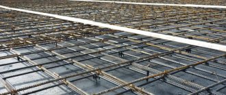
Monolithic reinforcing mesh
As for the rules in accordance with which the reinforcement is laid, the step between the bars of the reinforcing mesh is 20 centimeters. Knowing this distance and the thickness of the rod, you can accurately calculate the number of rods needed to complete the work. It is enough to divide the width of the slab by the width of the step and add one rod. In this case, the result will be 8:0.2 + 1= 41.
If in our case the length and width of the slab are equal, then to calculate the number of longitudinal rods the resulting number can be multiplied by 2. In another case, the calculation can also be carried out using the size of the length of the slab. Therefore, 41x2=82 rods.
This means that after calculating the number of rods for the first layer, you can multiply the result by 2 and get the total number. 82x2=164 rods. To ensure communication between mesh layers, a reliable connection will be required. For this purpose, special fasteners are used. The total length will be 164x6=984 meters, since 164 is the total number of rods, and 6 is the standard length of one rod.
Knitting of the reinforcing mesh is done using a special knitting wire. Welding contributes to the destruction of the structure due to the effects of corrosion. To determine the number of points at which the rods intersect, it is enough to multiply the number of rods used by the same number. 41x41 = 1681. For each node you will need at least 30 centimeters of wire, which means 1681x30 = 5043 m of wire.
Watch the video on how to properly tie reinforcement.
You can calculate the reinforcement for a slab foundation yourself. In such calculations, knitting, laying, and mesh pitch are taken into account. But specialized organizations will perform such calculations with higher accuracy thanks to software developed for designers.
Reinforcement coefficient as the main indicator of structural strength
Building codes establish the minimum reinforcement strength that is required for precast concrete products to withstand the intended load. The coefficient is calculated using the following formula:
μ = [Sa/(V∙H)]∙100%, where:
Sa is the cross-sectional area of the rods
B - width of the product (plates, strips)
H - its height
The reinforcing indicator varies depending on the depth of the foundation, the length and width of the tape, the expected load and other factors.
How to use the calculator
The calculator allows you to approximately calculate the amount of building materials for a slab foundation - reinforcement, concrete, boards for formwork, waterproofing, sand and crushed stone for a cushion, in order to check with the construction estimate or quickly calculate how much to order materials if you are building without a project. Do not be under the illusion that using an online calculator you can calculate the foundation based on loads; for this, at a minimum, you need to do geological surveys and have a house design in hand. For such calculations, please contact the designers.
Reinforcement
In the parameters:
House material - the choice of material does not affect the calculation, but only displays in the calculation table the recommended pitch of the slab reinforcement cell. In any case, the cell pitch must be calculated by the house designer; this value is given for reference.
The diameter of the working reinforcement is the diameter of the main working reinforcement (mesh) of the foundation from your project.
The pitch of the working reinforcement cell is the distance between the rows of working reinforcement.
Grid pitch
The diameter of the transverse reinforcement is the diameter of the reinforcement that serves to separate the lower and upper layers of reinforcement (spider).
Rebar spider
In counting:
The recommended diameter of the working reinforcement depends on the larger length and width of the slab. From 0 to 3 meters, recommended diameter = 10 mm, from 3 to 10 meters diameter = 12 mm, from 10 to 20 meters diameter = 14 mm. This value is for reference only.
Recommended diameter of transverse reinforcement - if the height of the slab is less than 30 cm, then diameter = 8 mm, if the height of the slab is more than 30 cm, then diameter = 10 mm. The value is for reference only.
The recommended cell size of working reinforcement depends on the selected house material. The value is for reference only.
Number of layers of working reinforcement - if the height of the slab is less than or equal to 15 cm, then the number of layers (grids) = 1, if the height of the slab is more than 15 cm, the number of layers of working reinforcement = 2.
The minimum overlap of working reinforcement when connecting in one row = 40 times the diameter of the working reinforcement.
The length of the working reinforcement is calculated taking into account the reinforcement under the walls - one row of reinforcement is added along the edges of the foundation (the cell pitch is half the specified one), the reinforcement under the internal walls must be taken into account independently.
The number of stands is calculated with a density of 2 pieces per m². By reinforcement for strengthening the ends we mean U-shaped clamps for strengthening the ends (see figure below):
Formwork
Here you set only the height (width) of the boards for the formwork itself and for the vertical supports in increments of 0.5 meters. The length of all boards is taken to be 6 m. The thickness of the formwork boards is taken to be 40 mm, the thickness of the boards for supports is taken to be 50 mm. The length of the spacers is not calculated, because not everyone uses them.
Pillow
Extending the pillow beyond the foundation - the pillow is always made a little wider than the slab itself, usually 20-30 cm, sometimes the pillow is made immediately under the blind area - about 1 meter wider than the slab.
Cost of materials
The cost does not include concrete for the footing, geotextiles and waterproofing, since these elements are not strictly necessary in the design of a slab foundation, and not everyone makes them.
Good publicity
Wall reinforcement
As we said, concrete is not the most common material for private construction due to its large mass, as well as the complexity of delivery and the need to rent a large amount of special equipment. For monolithic walls, vertical reinforcements are first installed, on which the spacing of future horizontal rods has already been marked. The step should be 5-10 centimeters. Next, the reinforced frame is knitted, then poured.
The question of whether it is necessary to reinforce walls made of aerated concrete deserves special consideration. Most builders agree that there is no need to reinforce aerated concrete masonry. In Russia there is no legislative framework that would provide for mandatory reinforcement, except in cases where the distance between expansion joints exceeds 30 meters. In order to prevent cracks that arise due to temperature and shrinkage deformation from opening, you simply need to make the masonry fragments short enough, without separating them with expansion joints. Reinforcement must be done in those blind areas of the masonry, the length of which exceeds 6 meters, if the thickness of the masonry itself does not exceed 300 mm. Walls of greater thickness, provided they are laid correctly, are not susceptible to cracks from the mentioned factors, and therefore do not need to be strengthened through reinforcement.
The article uses photographs from the site https://s-stroit.ru/
To select the right contractor who has a thorough understanding of low-rise building codes, search the Building Companion directory. The profile of each company contains the necessary information, portfolio, reviews, and you can place a request for an estimate of the cost of the service. Find a general contracting and construction supervision company »
Features of foundation reinforcement
Unlike reinforcing floors, reinforcement in foundation slabs must be laid in an uneven order. To ensure maximum reinforcement of areas under increased load, the rods must be laid taking into account the level of punching in one place or another of the slab. The exception is a thin foundation (no more than 150 mm) laid under light structures - in such cases the layout is carried out in the form of a grid.
In residential construction, the thickness of the foundation usually varies between 20-30 cm and depends on the mass of the structure and the properties of the soil. To ensure the maximum possible reinforcement, the reinforcement should be laid in two layers, on top of which it is necessary to provide a protective concrete layer to prevent corrosion.
Useful tips
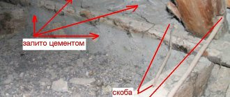
Before you begin to calculate the amount of materials and the foundation itself, you need to study all the features of the soil. Heaving soil can rise and fall several centimeters throughout the year. If this is not taken into account, then over time the foundation will begin to burst under loads, and cracks will spread throughout the house.
The reinforcement is connected to each other with wire, which makes it movable and because of this, the hardened concrete, under the influence of soil deformations, will also be movable, which will preserve its structure and guarantee the absence of cracks.
Video on the topic:
Calculation
Let's look at how materials are calculated for an 8 by 8 meter slab. We will make reinforcement in increments of 20 centimeters, rods with a diameter of 14 in two layers, for vertical rods 8 millimeters, the spacing is the same. We take the concrete used for the slab of class B20 (in strength it corresponds to grade M250) for preparation of class B7.5. Let's take the thickness of the slab to be 25 cm.
- Concrete for slab B20: 8.2 x 8.2 = 67.24 m²;
- Let's calculate the cubic capacity, that is, the volume of concrete required: 67.24 m² x 0.25 m = 16.81 m³;
- Consumption of the amount of material for reinforcement, taking into account the provision of a protective layer for the slab: 8200 – 60 = 8140 millimeters rod length. Based on a step of 20 cm, we calculate their number for 1 direction, divide 8200 by 200 = 41 pieces x 2 sides = 82 pieces x 2 layers of the entire slab = 164 rods;
- Let's calculate the total length: 164 x 8.14 = 1334.96 meters. The weight of 1 meter of 14-diameter reinforcement is 1.2 kilograms. Thus, the mass of the entire working reinforcement is: 1334.96 meters x 1.2 = 1601.252 kilograms;
- Let's move on to the vertical reinforcement bars, its length will be equal to the difference of 25 cm and 6 cm = 19 cm. Let's take a step of 40 centimeters, we get 21 pieces x 21 pieces = 441 units, we get the mass from the expression 441 x 0.19 x 0.395 = 33, 1 kg;
- We calculate the consumption of class B7.5 concrete for preparation as: 8.2 x 8.2 x 0.05 (specified thickness) = 3.3 meters³;
- We calculate geotextiles and waterproofing of the slab as the area of the slab adding a little margin: 67.24 meters²;
- We consider the sand cushion by multiplying the sides of the slab and the height of the cushion, taking into account that it extends beyond its boundaries by 0.1 meter on each side, that is, 8.4 x 8.4 x 0.5 = 32.5 cubic meters of sand.
Note that for two-story houses made of aerated concrete (gas silicate), frame houses and garages (made of brick), the thickness of the slab will be 20-25 centimeters. For heavier buildings, as well as two-story houses made of brick, concrete, timber, the thickness should be 25-30 cm. For light structures, for example, garages and gazebos, it is enough to take a foundation slab thickness of 10-15 centimeters.
Reinforcement of a foundation 10-15 cm thick is done in one layer, 20-30 cm thick - in two layers (volumetric).