Home |GOSTs and SNiPs |Concrete preparation for the foundation: building codes and rules for footing
Date: October 27, 2018
Comments: 1
When carrying out construction, it is important to correctly perform preliminary calculations, as well as technically competent and high-quality preparation of the foundation, which determines the stability of the building’s foundation. Concrete preparation for the foundation is a complex of works for the construction of a cushion under a future facility.
The choice of the optimal option for performing preparatory measures affects the reliability of the foundation and the service life of the construction project.
A properly prepared base, proportional to the area, redistributes the loads acting on the ground and prevents leakage of the cement mass, which is possible during the process of pouring concrete mortar.
Forming a pillow is a responsible operation. That is why the technical requirements that determine the specifics of preparatory activities, the technology, the required material, and the thickness of the layer used for the pillow are regulated by SNiP and a set of rules, the recommendations of which we will consider further in more detail.
There are a number of technical requirements regulating the technology of preparatory work, the choice of material and the thickness of the layer used for the pillow
Regulations
What regulatory documents and rules must the installation of concrete preparation for the foundation meet?
When carrying out industrial and civil construction, the construction of any types of structures is subject to special provisions given in industry and state standards, building codes and regulations, as well as codes of practice. The main documentation regulating the specifics of the work is:
- SNiP 52–01, issued in 2003, deals with structures made of concrete and reinforced concrete;
- SP 50–101, approved in 2004, containing requirements for the design and construction of foundation foundations;
- SP 52–101 (2003), devoted to structures without prestressed reinforcement;
- SNiP 2.02.01, developed in 1983, regulating the parameters of the foundations of construction projects;
- SP 63.13330.2012 is a set of rules that combines requirements for building structures.
These standards clearly define the features of activities related to the construction of foundations and their design. They take into account:
- Soil characteristics at the construction site.
- Specifics of the development object.
- Environmental requirements.
- Actionable efforts.
- Degree of seismic activity.
The requirements of regulatory documents are subject to strict compliance by construction companies and organizations carrying out design work.
The construction of any structures during the construction of civil and industrial facilities is subject to certain requirements
Laying concrete mixture in a structure
§ E4-1-49. Laying concrete mixture in a structure
Instructions for application of standards
The standards provide for the reception and placement of concrete mixture in buckets supplied by a crane, conveyor, concrete pumps and dump trucks directly into the structure being concreted or along trays (trunks), with partial transfer of the concrete mixture. The laid concrete mixture is leveled and compacted using vibrators. The exposed concrete surface is smoothed. During operation, trays or trunks are cleaned and rearranged.
Scope of work
1. Reception of concrete mixture. 2. Laying the concrete mixture directly to the laying site or along trays (trunks). 3. Leveling the concrete mixture with partial transfer. 4. Compacting the concrete mixture with vibrators. 5. Smoothing the exposed concrete surface. 6. Rearranging vibrators, trays or trunks and cleaning them.
Squad composition
Concrete worker 4 grades. - 1 » 2 » - 1
A. MASSIVES AND INDIVIDUAL FOUNDATIONS
Table 1
Time standards and prices for 1 m³ of concrete or reinforced concrete in practice
| Concrete mix supply method | N.v. | Dist. | № | |
| Crane in tubs in a structure with a volume, m3, up to 3 | 0,42 | 0-30 | 1 | |
| Taps in tubs per structure, volume, m3, up to 5 | 0,34 | 0-24,3 | 2 | |
| Crane in buckets, conveyors, concrete pumps into a structure with a volume, m3: | ||||
| before | 10 | 0,33 | 0-23,6 | 3 |
| « | 25 | 0,26 | 0-18,6 | 4 |
| « | 30 | 0,23 | 0-16,4 | 5 |
| St. | 30 | 0,22 | 0-15,7 | 6 |
| Dump trucks with a carrying capacity of up to 5 tons (regardless of the volume of the structure) | 0,34 | 0-24,3 | 7 | |
Notes: 1. When laying concrete mixture with “raisins” N.v. and Rasc. multiply by 1.2 (PR-1), including the placement of “raisins”. Take the scope of work along with the “raisins”. 2. When laying concrete mixture in densely reinforced foundations N.v. and Rasc. multiply by 1.1 (PR-2), unreinforced - by 0.9 (PR-3). 3. When laying concrete mixture in masses as part of a concrete worker’s unit, 4 grades. replace with concrete worker 3 raz., and Rast. recalculate.
B. STRIP FOUNDATIONS AND ELEMENTS OF FRAME STRUCTURES
table 2
Time standards and prices for 1 m³ of concrete or reinforced concrete in practice
| Constructions | N.v. | Dist. | № | |
| Strip foundations width, mm | up to 600 | 0,3 | 0-21,5 | 1 |
| Strip foundations width, mm | St. 600 | 0,23 | 0-16,4 | 2 |
| Columns and frame posts with the smallest side | up to 300 | 2,2 | 1-57 | 3 |
| cross-section of a column or rack, mm | up to 500 | 1,5 | 1-07 | 4 |
| St. 500 | 1,1 | 0-78,7 | 5 | |
| Column capitals for beamless floors | 0,82 | 0-58,6 | 6 | |
| Beams, purlins and crossbars with width, mm | up to 150 | 1,4 | 1-00 | 7 |
| up to 250 | 1,1 | 0-78,7 | 8 | |
| St. 250 | 0,89 | 0-63,6 | 9 | |
| Slabs and ribbed floors (including beams and | to 10 | 1,3 | 0-93 | 10 |
| purlins) with area between beams, m2 | up to 20 | 0,98 | 0-70,1 | 11 |
| St. 20 | 0,81 | 0-57,9 | 12 | |
| Beamless floors with an area between the axes | to 10 | 0,85 | 0-60,8 | 13 |
| columns, m2 | up to 20 | 0,69 | 0-49,3 | 14 |
| St. 20 | 0,57 | 0-40,8 | 15 | |
Notes: 1. When concreting columns and racks of reinforced concrete frames on the side or individual columns in stone buildings N.v. and Rasc. lines No. 3-6 multiply by 1.25 (PR-4). 2. When concreting slabs (except beamless) with double reinforcement N.v. and Rasc. lines No. 10-12 multiply by 1.15 (PR-5). 3. Concreting of floors with a slab located below the beams should be rated separately: the slab as beamless coverings - according to lines No. 13-15, and beams - according to lines No. 7-9 of this paragraph. 4. The bottoms of the tanks should be standardized as beamless floors (lines No. 13-15). 5. When concreting floors up to 5 m2 in one place N.v. and Rasc. lines No. 10 and 13 multiply by 1.2 (PR-6). 6. When laying concrete mixture with “raisins” in strip foundations N.v. and Rasc. lines No. 1 and 2 multiply by 1.2 (PR-7). Take the scope of work along with the “raisins”.
B. WALLS AND PARTITIONS
Table 3
Time standards and prices for 1 m³ of concrete or reinforced concrete in practice
| Constructions | Thickness of walls or partitions, mm | ||||||
| up to 100 | up to 150 | up to 200 | up to 300 | St. 300 | |||
| Straight vertical walls or partitions | 3,5 2-50 | 2,3 1-64 | 1,6 1-14 | 1,2 0-85,8 | 0,79 0-56,5 | 1 | |
| Straight inclined and curved tank walls | up to 1 | 5,9 4-22 | 5,4 3-86 | — | — | — | 2 |
| radius, m | until 3 | 4,8 3-43 | 4,1 2-93 | 2,8 2-00 | 1,9 1-36 | 1,4 1-00 | 3 |
| up to 5 | 4,4 3-15 | 3,3 2-36 | 2,2 1-57 | 1,7 1-22 | 1,2 0-85,8 | 4 | |
| to 10 | 3,4 2-43 | 2,7 1-93 | 1,9 1-36 | 1,4 1-00 | 0,9 0-64,4 | 5 | |
| St. 10 | 2,8 2-00 | 2,2 1-57 | 1,5 1-07 | 1,1 0-78,7 | 0,74 0-52,9 | 6 | |
| Sloping walls of bunkers with capacity, m3 | to 10 | 4,4 3-15 | 3,4 2-43 | 2,3 1-64 | 1,7 1-22 | 1,2 0-85,8 | 7 |
| up to 15 | 3,6 2-57 | 2,8 2-00 | 1,9 1-36 | 1,4 1-00 | 0,94 0-67,2 | 8 | |
| up to 20 | 2,9 2-07 | 2,2 1-57 | 1,5 1-07 | 1,1 0-78,7 | 0,76 0-54,3 | 9 | |
| St. 20 | 2,3 1-64 | 2 1-43 | 1,2 0-85,8 | 0,86 0-61,5 | 0,6 0-42,9 | 10 | |
| A | b | V | G | d | № | ||
Note. The standards provide for concreting walls with single reinforcement. When concreting walls without reinforcement N.v. and Rasc. multiply by 0.75 (PR-8), when concreting walls with double reinforcement N.v. and Rasc. multiply column “a” and “b” by 1.25 (PR-9), column “c” - “d” - by 1.15 (PR-10).
D. STAIRWAYS
Table 4
Time standards and prices for 1 m³ of concrete or reinforced concrete in practice
| Constructions | N.v. | Dist. | № |
| Stringers, staircases and balcony landings | 2,1 | 1-50 | 1 |
| Flights of stairs | 4,5 | 3-22 | 2 |
Types of preparation
The requirements of building codes and codes of practice stipulate that in order to form a foundation it is necessary to perform one of the specified types of preparation. We list the possible options:
- the base is made of lean concrete, characterized by a low grade and a low percentage of binding ingredients;
- crushed stone preparation for the base, 200 mm thick, providing a significant reduction in cement consumption. The crushed stone is compacted and filled with bitumen solution;
- profile membrane base, combining the features of the above types of work.
Increased strength is provided by the first option, after which it is more convenient to carry out further work on arranging the foundation. Let's look at it in detail.
The main tasks of the footing
The installation of concrete preparation for the foundation ensures the required state of the foundation, which has the necessary load-bearing capacity sufficient to withstand the applied forces. That is why building codes pay increased attention to it. What is the main purpose of the concrete base, which is the basis of monolithic structures? What tasks does it perform?
Concrete preparation for the foundation is used primarily in the construction of slab and strip reinforced structures
Main functions:
- Ensuring the protection of the poured solution from leakage, which contributes to the rapid hardening of the base in accordance with the requirements of the technology, improving its quality. Lack of moisture causes cracking of the massif, reducing the strength of the base and its subsequent destruction over time.
- Creation of a flat surface that allows a geometrically correct, stable installation of the base frame and reinforcement in accordance with the requirements of SNiP.
- Leveling the reaction of the soil on the base of the sole, uniform distribution of force over the entire area.
- Preventing possible soil shrinkage under the influence of point forces and significant loads.
Concrete and reinforced concrete foundations. Permissible size deviations according to SP
Requirements for maximum deviations of completed concrete and reinforced concrete foundation structures are given in section 5.18 SP 70.13330.2012 Load-bearing and enclosing structures. Updated version of SNiP 3.03.01-87. Let us highlight the points of this regulatory document that relate to permissible deviations of the geometric parameters of foundation structures from the design values.
According to clause 5.18.1, one of the points of construction control of completed foundation structures is their checking for compliance of the actual geometric parameters of the structures with the working drawings and deviations according to Table 5.12. In accordance with clause 5.18.3, the requirements for completed concrete and reinforced concrete structures or parts of structures are given in Table 5.12.
Table 5.12 SP 70.13330.2012
| Parameter | Maximum deviations, mm | Control (method, volume, type of registration) |
| 1 Deviation of the lines of intersection planes from the vertical or design slope to the entire height of structures for foundations | 20 | Measuring, each structural element, work log |
| 3 Deviation from straightness and flatness of the surface over a length of 1-3 m and local unevenness of the concrete surface | According to Appendix X for monolithic structures. According to GOST 13015 for prefabricated structures | Measuring, at least 5 measurements for every 50 m of length and every 150 m of the surface of structures, work log |
| 4 Deviation of horizontal planes over the entire area being verified | 20 | Measuring, at least 5 measurements for every 50 m of length and every 150 m of the surface of structures, work log |
| 5 Deviation of lengths or spans of elements, clear dimensions | ±20 | Measuring, each element, work log |
| 6 Cross-sectional dimension of element h: | Measuring, each element (at least one measurement per 100 m area of floor slabs and coverings), work log. | |
| h < 200 mm | +6; -3 | |
| h = 400 mm | +11; -9 | |
| h < 2000 mm | +25; -20 | |
| For intermediate values of h, the tolerance value is determined by interpolation. | ||
| 7 Deviation from alignment of vertical structures | 15 | Measuring (executive geodetic survey), each structural element, work log |
| 9 Markings of surfaces and embedded products that serve as supports for steel or precast concrete columns and other precast elements | -5 | Measuring, each support element, executive circuit |
| 10 Location of anchor bolts: | The same, each foundation bolt, executive diagram | |
| in plan inside the support contour | 5 | |
| in plan outside the support contour | 10 | |
| in height | +20 |
According to clause 5.18.16, exposure of working and structural reinforcement is not allowed on the surface of foundation structures, with the exception of reinforcement outlets provided for in the working drawings.
They must also meet the requirements given in Table 6.5.
Table 6.5 SP 70.13330.2012
| Parameter | Parameter value, cm | Control (method, volume, type of registration) |
| Deviation of the actual dimensions and position of on-site (and prefabricated) foundations and grillages from the design ones, see: | ±5 (±2) | Acceptance (measurements with theodolite, tape and ruler) |
| dimensions in terms of | +2; -0,5 | Same |
| protective layer thickness | (+1; -0,5) | « |
| height position of the top (edge) of the foundation or grillage | ±2 (±1) | « |
| plan positions relative to alignment axes | 2,5 (1) | « |
| Note - The values given in the table in brackets refer to prefabricated foundations and grillages. | ||
We will also add the requirements for prefabricated grillages given in clause 12.8.27 SP 45.13330.2017 “Earth structures, foundations and foundations. Updated version of SNiP 3.02.01-87" according to which, when carrying out work on the installation of pile foundations, the composition of controlled indicators, the scope and methods of control must correspond to Table 12.1.
Table 12.1 SP 45.13330.2017 (only items with requirements for pile grillages are left)
| 18 Installation of prefabricated grillages: | Displacement relative to the alignment axes, mm | Deviations in surface marks, mm | Measuring, each grillage | ||
| a) foundations of residential and public buildings | ±10 | ±5 | |||
| b) foundations of industrial buildings | ±20 | ±10 | |||
Piles. Permissible displacements in the plan and elevation of the head according to SP
Requirements for the calculation part
Building rules require calculation of the forces that the foundation can absorb in the following cases:
- In the presence of severe compressive forces.
- When the construction site is located near embankments, slopes or slopes.
- When arranging the base of the foundation located on weak soils.
The standards allow not to carry out calculations of bearing loads if, according to the project, measures will be taken that do not allow soil movement.
As forces acting on the base, the set of rules takes into account all transmitted loads, acting both short-term and throughout the entire period of operation. The mass of the part of the object below the zero mark is also taken into account.
Preparing the foundation pit
The main stages of work to prepare the soil for installing a concrete foundation include:
- arrangement and marking of the pit, taking into account the future thickness of the layer of sand-gravel mixture and concrete;
- planning and cleaning the bottom of the excavation;
- compaction of loose soil using vibrating plates;
Regardless of the type of soil, at the first stage of work on preparing lean concrete for the foundation, the bottom of the excavation should be leveled
- additional moistening or drying of the soil, depending on the results of compaction work;
- adding sand-crushed stone fraction 10 cm thick, necessary for drainage;
- compaction of the massif;
- applying a waterproofing layer of film or roofing material sheets;
- assembly of formwork with a height of no more than 30 cm for concreting.
Only after this they begin concreting work. These are the main stages provided for by the standards that make up the concrete preparation for the foundation.
Causes
The technology of pouring a monolith involves the use of two methods - continuous pouring of the solution and laying cards in the form of separate blocks. The preferred option is to use the first method, which provides better conditions for setting and hardening of concrete.
This installation assumes the plasticity of the lower layer at the time of pouring the upper one, which guarantees good adhesion, uniform strength gain and solidity. But it is not always possible to implement the method.
The main reasons for pouring concrete with cold joints:
- Limited working shifts, interruptions in the operation of equipment and special transport.
- Time costs for installing reinforcement frames, scaffolding, and formwork assembly.
- Limiting loads on a surface that has not yet gained sufficient strength.
- Concreting of embedded parts, communication inputs.
- Ensuring directional deformations of products and elements under loading.
- The first stage is to create the horizontal part of the structure, the second - the vertical part.
Reasons for the spontaneous appearance of cold seams:
- Long breaks in work after the solution has set.
- Lack of formwork, technological equipment, scaffolding.
- Insufficient volume of concrete to pour in one cycle.
- Understaffing of the team of workers.
- Low power of equipment, insufficient qualifications of personnel.
In cases where it is impossible to avoid this, concreting seams and their locations are thought out in advance. It is advisable to avoid the possibility of spontaneous seams appearing, but to coordinate them in advance with the designer, to do them in accordance with technological breaks, and to follow the technology. It is prohibited to make such joints in structures where there are tensile forces.
In the drawings, a cold concreting joint is indicated by a callout with its name and an indication of the exact dimensions from the axes of the structure or building. In addition to technological ones, expansion joints are often made in the structure, the main task of which is to compensate for the shrinkage and temperature movements of the concrete monolith.
Insulating strips, special slats or cords are installed in the resulting gap. These joints are also necessarily included in the design drawing with a designation.
Disadvantages of working seams
The main disadvantages of arranging cold seams can be avoided if they are taken into account in the project and carried out correctly. When the sutures were not intended, but they happened spontaneously, significant problems may arise.
The main disadvantages of cold seams:
- A weakened section appears in the joint area, which poses a danger to critical and loaded structures, as the load-bearing capacity is reduced.
- Water can get into microcracks, causing leaks and corrosion of the reinforcement and concrete itself. In winter, the water freezes and destroys the monolith.
- Reduced water resistance, frost resistance, and mechanical strength of the stone.
- Significant reduction in the service life of the structure/building.
- The presence of noticeable defects on the surface of the monolith.
In the joint zone, a point of internal stress with a predominance of tensile forces appears on the concrete surface. Concrete works great in compression, but it does not withstand other types of loads so easily. The seam area deforms gradually, increasing the risk of destruction of the entire building or structure.
The situation becomes even more serious if water gets into cold seams. It washes out the components of the stone and accelerates the destruction of the material. This is especially dangerous in cases where the foundation monolith is buried in the soil; there are also risks for reservoirs and hydraulic structures. Aggressive substances from the soil provoke chemical corrosion of concrete.
If cold seams are not provided for in the design or are not made according to the technology, water that gets inside will also contribute to mechanical damage to the monolith in winter due to alternating freezing and thawing.
Location of seams according to SNiP
The norms and rules for performing cold concreting joints are prescribed in the relevant documents. The main requirement is this: regardless of the conditions, the seam should not become a stress concentration zone. The location of the joint must be perpendicular to the axis of columns, beams, any slab, and other concreted elements/structures.
When and where can cold seams be made:
- For individual beams with a seam within the middle third of the span.
- For beams of large dimensions monolithically combined with slabs (the joint is made at 20-30 millimeters below the surface of the slab).
- For columns, provided that the joint is at the level of the bottom of capitals, purlins, crane beams or the top of the foundation.
- For massifs, vaults, arches, tanks, complex structures, structures where seams are located in the areas provided for by the design.
- For flat slabs, where the seam can be placed anywhere, but only parallel to the smaller side of the slab.
The ideal option is when the cold seam coincides with the position of the minimum (zero) shear force in the monolith structure. Such a place is found when performing special calculations (in the diagram of transverse forces).
When carrying out calculations manually, they find the place where the diagram intersects the horizontal (it is here that the transverse force usually tends to zero). When carrying out calculations using programs, diagrams of transverse forces or their color schemes are analyzed (this is more clear).
In all diagrams and drawings, the junction of concrete layers is indicated by a dotted line. To more clearly define, a callout is made with the name “working joint of concreting”. The diagrams indicated in the drawings must be clearly executed; changing the position of the joints is prohibited. All recommendations and standards are specified in SNiP 3.03.01-87.
Performing reinforcement
According to building codes, concrete preparation for the foundation requires strengthening the concrete mass with steel reinforcement. This measure improves the reliability of the part of the building located below the zero level and strengthens the footing.
The base is reinforced with steel mesh connected with special wire with a diameter of 8 millimeters. The structure is laid on the base before the formwork is filled with the mixture. The standards provide for the installation of vertically located steel rods that ensure a strong connection between the foundation and the base. Steel rods must rise above the surface of the base by at least 20 centimeters.
Reinforcement significantly strengthens the concrete base and increases the reliability of the underground part of the structure
Reinforcement.
Before starting concreting, check the accuracy of installation and the quality of fastening of reinforcing bars, meshes or frames, as well as compliance of the provided thickness of protective layers with standards and technical conditions. It is necessary to ensure that the reinforcement bars are dry and clean so that their adhesion to the concrete does not decrease. Permissible deviations when installing fittings are, mm:
in the distances between separately installed working rods:
for columns, beams and arches. +10
- " - slabs, walls and foundations for the structure frame + 20
—“— massive structures. +30
in the distances between rows of reinforcement when reinforced in several rows in height:
in structures more than 1 m thick and foundations for structures and technological equipment. +20
in beams, arches and slabs with a thickness of more than 100 mm. +5
in slabs up to 100 mm thick with a designed protective layer thickness of up to 10 mm. +3
in the distances between the clamps of beams and columns and between the connections of the reinforcement cages. +10
from the vertical or horizontal of the clamps (except when inclined clamps are provided for by the design). 10
in the position of the axes of the rods at the ends of the welded frames, joined in place with other frames with a diameter of:
40 mm or more. ±10
in the location of the joints of the rods along the length of the element:
in frames and thin-walled structures. +25
in massive structures. +50
in the position of reinforcement elements of massive structures (frames, beams, trusses) from design:
Features of concrete preparation
The main provisions contained in building codes and codes of practice related to the implementation of a cushion based on lean concrete:
- It is allowed to use a solution of grade M50 and higher. To perform the work, lean concrete is used, which is a type of cement mortar that contains no more than 6% class B15 cement. Sand and gravel play the role of filler.
- The poured mass for foundation slabs or a monolithic base must extend beyond the level of the underground part of the structure and rise above it by 100-150 mm, which is ensured by the design of the formwork prepared in advance.
- The solution is poured onto a pre-made crushed stone-sand base.
- Air bubbles are removed by compacting the mixture.
- Protection against surface dehydration is provided by polyethylene film, which is used to cover the poured surface in the first days.
Is it possible to make a footing without reinforcement? What is the recommended thickness of the concrete footing made without reinforcement by building codes? Building rules allow this option, for which the thickness of the concrete layer is 150-200 mm.
When arranging a reinforced base for a foundation, the set of rules allows for a reduced base height. The layer thickness in this case is 60-100 mm. The size is influenced by the mass of the structure, the level of groundwater, and the type of soil.
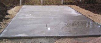
Construction requirements provide for a minimum height of the concrete layer, which must rise above the ground surface by no less than 15 cm
According to SNiP, the tolerance for surface flatness when forming a monolithic strip does not exceed 0.5 cm for each meter of length and no more than 5 centimeters for solid slabs with a width of over 25 meters.
Concrete preparation for the foundation is especially important if construction activities are carried out in winter, since a flat surface facilitates the further implementation of the foundation work envisaged by the project.
Acceptance of concrete and reinforced concrete structures or parts of structures
p>18.1
Construction inspection of completed structures or parts of buildings and structures should be carried out for compliance with:
- actual geometric parameters of structures, working drawings and deviations according to table 5.12;
- surface quality and appearance of monolithic structures (Appendix X);
- properties of concrete to design requirements according to 5.5 and reinforcement - according to 5.16;
- materials, semi-finished products and products used in the design, requirements of design documentation according to the incoming control of technical documentation.
18.2
Acceptance of completed concrete and reinforced concrete structures or parts of structures should be formalized in the prescribed manner by an act of inspection of hidden work and an act of inspection of critical structures.
18.3
The requirements for finished concrete and reinforced concrete structures or parts of structures are given in Table 5.12.
Table 5.12. SP 70.13330.2012
Load-bearing and enclosing structures. Updated version of SNiP 3.03.01-87
| Parameter | Maximum deviations, mm | Control (method, volume, type of registration) |
| 1 Deviation of the lines of the intersection planes from the vertical or the design slope to the entire height of the structures for: | Measuring, each structural element, work log | |
| foundations | 20 | |
| walls and columns supporting monolithic coverings and ceilings | 15 | |
| walls and columns supporting precast beam structures | 10 | |
| walls of buildings and structures erected in sliding formwork, in the absence of intermediate floors | 1/500 of the height of the structure, but not more than 100 | |
| walls of buildings and structures erected in sliding formwork, in the presence of intermediate floors | 1/1000 of the height of the structure, but not more than 50 | |
| 2 Deviation of the axes of columns of frame buildings over the entire height of the building (n-number of floors) | ∑h (200 | Measuring, all columns and lines of their intersection, work log |
| 3 Deviation from straightness and flatness of the surface over a length of 1 - 3 m and local unevenness of the concrete surface | According to Appendix X for monolithic structures. According to GOST 13015 for prefabricated structures | Measuring, at least 5 measurements for every 50 m of length and every 150 m of the surface of structures, work log |
| 4 Deviation of horizontal planes over the entire area being verified | 20 | Measuring, at least 5 measurements for every 50 m of length and every 150 m of the surface of structures, work log |
| 5 Deviation of lengths or spans of elements, clear dimensions | ±20 | Measuring, each element, work log |
| 6 Element cross-sectional dimension h at: | Measuring, each element (at least one measurement per 100 m area of floor slabs and coverings), work log | |
| h < 200 mm | +6; | |
| h = 400 mm | -3 + 11; | |
| h > 2000 mm | -9 + 25; | |
| At intermediate values h the tolerance value is taken by interpolation | -20 | |
| 7 Deviation from alignment of vertical structures | 15 | Measuring (executive geodetic survey), each structural element, work log |
| 8 Deviation in the sizes of window, door and other openings | ±12 | Measuring, each opening, work log |
| 9 Markings of surfaces and embedded products that serve as supports for steel or precast concrete columns and other precast elements | -5 | Measuring, each support element, executive circuit |
| 10 Location of anchor bolts: | The same, each foundation bolt, executive diagram | |
| in plan inside the support contour | 5 | |
| in plan outside the support contour | 10 | |
| in height | +20 |
18.4
During acceptance inspection of the appearance and quality of structure surfaces (presence of cracks, concrete chips, cavities, exposure of reinforcing bars and other defects), each structure is visually checked. Requirements for the surface quality of monolithic structures are given in Appendix X. Special requirements for the surface quality of monolithic structures must be presented in the design documentation. Requirements for the quality of the surface of structures can be established for monolithic structures in accordance with GOST 13015.
18.5
When accepting monolithic structures at a construction site, concrete quality control should be carried out by comprehensive application of the following testing and control methods:
- concrete quality indicators for strength in structures according to GOST 18105;
- frost resistance according to GOST 10060;
- water resistance according to GOST 12730.5.
Note.
If necessary, control of other indicators established in the design documentation and GOST 26633 is carried out.
18.6
Determination of concrete quality indicators in terms of strength in structures upon acceptance in accordance with GOST 18105 is carried out using non-destructive methods or using samples taken from structures.
18.7
When monitoring the strength of concrete structures at an intermediate age, at least one structure of each type (column, wall, ceiling, crossbars, etc.) from the controlled batch is controlled using non-destructive methods.
18.8
When monitoring the strength of concrete structures using non-destructive methods at design age, continuous non-destructive testing of the strength of concrete of all structures of the controlled batch is carried out. At the same time, according to GOST 18105, the number of test sections must be at least:
- three for each grip for flat structures (wall, ceiling, foundation slab);
- one per 4 m length (or three per grip) for each linear horizontal structure (beam, crossbars);
- six for each structure - for linear vertical structures (column, pylon).
18.9
The total number of measurement sections for calculating the characteristics of the uniformity of concrete strength of a batch of structures must be at least 20. The number of measurements carried out at each controlled section is taken in accordance with GOST 17624 or GOST 22690.
During inspection control (conducting surveys and expert quality assessment) of linear vertical structures, the number of controlled areas must be at least four.
18.10
Determination of concrete quality indicators in terms of strength in structures upon acceptance based on samples is carried out in cases where this is provided for in the design documentation.
18.11
Sampling from structures to determine concrete quality indicators in terms of strength should be carried out in accordance with GOST 28570.
18.12
Evaluation and acceptance of concrete structures based on samples taken from structures is carried out according to GOST 18105 from the condition
V
f >
V
and is carried out:
- with determining the characteristics of concrete strength homogeneity using data from current monitoring of concrete strength of an individual structure or batch (group) of structures with a number of test sites of at least three;
- without determining the characteristics of concrete strength homogeneity when using data from current monitoring of the concrete strength of a separate structure or the capture of a structure with a number of test sections of at least three. In this case, the actual concrete class B
f is taken equal to 80% of the average concrete strength of the controlled sections of the structure or structure, but not more than the minimum particular value of the concrete strength of an individual structure or section of the structure included in the controlled batch.
Control of samples taken from structures is also subject to those indicators of concrete quality that are given in the design documentation.
18.13
For concrete classes B60 and higher, assessment and acceptance of concrete strength is carried out in accordance with GOST 18105, taking into account the following requirements:
- the required strength coefficient is taken according to Table 2 of GOST 18105, but not less than 1.14;
- in the initial period, the level of required strength of concrete in a batch is taken in accordance with 6.8 GOST 18105 or according to scheme “G”;
- the actual class of concrete Vf
in a batch (group) of monolithic structures is determined by control samples made at the construction site, in exceptional cases, if it is impossible to determine the strength of concrete in structures using non-destructive methods using formulas; - with the number of single results from each batch of structures being at least six, but not more than 15, without taking into account the characteristics of concrete homogeneity in strength according to the formula
- with the number of individual results from each batch of structures being at least 15, taking into account the characteristics of concrete homogeneity in strength:
Vf
= 0,8
Rm
,
where Rm
— average actual strength of concrete in a batch (group) of structures according to testing of control samples, MPa;
Vf
=
Rm
(1 -
taVm
/ 100),
where ta
— coefficient adopted according to Table 3 of GOST 18105 depending on the number of unit values of concrete strength, according to which the coefficient of variation of concrete strength is calculated;
Vm
- the current coefficient of variation in the strength of concrete in a batch of structures according to testing of control samples.
18.14
A batch of structures is subject to acceptance for concrete strength, GOST 18105, if the actual concrete class
Vf
in each individual structure of this batch is not lower than the design concrete strength class
Vnorm
.
Vf
≥
Vnorm
18.15
The values of the actual concrete strength class of each structure must be given in the concrete work log.
18.16
Exposure of working and structural reinforcement on the surface of structures is not allowed, with the exception of reinforcement outlets provided for in the working drawings.
18.17
Open surfaces of steel embedded parts and reinforcement outlets must be cleared of concrete or mortar deposits.
18.18
Grease and rust stains are not allowed on the front surfaces of monolithic structures intended for painting.
18.19
Quality of relief, etc. surfaces that are not subject to further finishing (painting, pasting, cladding, etc.) must comply with the requirements of the design documentation.
18.20
The maximum permissible crack opening width should be set based on aesthetic considerations, requirements for the permeability of structures, as well as depending on the duration of the load, the type of reinforcing steel and its tendency to develop corrosion in the crack.
In this case, the maximum permissible value of the crack opening width аcrc, ult
should take no more than:
- from the condition of safety of reinforcement: 0.3 mm - with prolonged opening of cracks;
- 0.4 mm - with short-term opening of cracks;
- 0.2 mm - with prolonged crack opening;
For massive hydraulic structures, the maximum permissible values of crack opening width are established according to the relevant regulatory documents, depending on the operating conditions of the structures and other factors, but not more than 0.5 mm.
18.21
If the results of construction control (inspection of structures) reveal deviations in the quality of finished structures from the requirements of the project and Section 18 of this SP (geometric dimensions, quality of concrete and surfaces, reinforcement, location of embedded parts), an inspection report of concrete and reinforced concrete structures is drawn up, which is agreed upon with the design organization to ensure the safety of structures [8].
Performing crushed stone preparation
The use of prepared foundations based on crushed stone allows you to reduce the costs of construction activities. After all, cement is saved, and the cost of purchasing crushed stone is quite acceptable. Crushed stone preparation for the foundation is permitted by the set of rules and building codes. In this case, the layer thickness should be about 20 centimeters. The crushed stone layer must be thoroughly compacted and filled with liquid bitumen. Filling the bitumen solution is carried out if it is necessary to saturate the soil as much as possible or to form a waterproofing bitumen film.
This method does not provide high rigidity of the substrate and makes it difficult to carry out foundation measures. It is widely used for low-impact construction of technical facilities, utility rooms and auxiliary buildings.