- 1 Definition
- 2 Materials and characteristics
- 3 Purpose
- 4 Features
- 5 Marking
- 6 Difference between a crossbar and a beam
- 7 How to make a crossbar?
- 8 Conclusion
Construction has in its arsenal structural elements that allow the construction of openwork buildings. One of the most important products is reinforced concrete crossbars, which bear the weight of floor slabs of multi-story buildings. The reliability and durability of buildings depend on their quality and characteristics. The structural features of these reinforced concrete products are varied, so it is not always possible to see the fundamental differences between the beam and the crossbar.
Materials and characteristics
The basis of their strength is formed by concrete (heavy weight) of classes (compression) from B22.5 to B60. Reinforcement of products is carried out by metal rod thermomechanically strengthened and hot-rolled reinforcement with a periodic profile, as well as reinforcing steel ropes, reinforced reinforced steel of the prescribed classes and wire of various strengths.
The reinforced concrete crossbar must have the accumulated standard concrete strength, measured at three time points: tempering (70% and 85% in warm and cold times, respectively), transfer, design. Such products have high levels of frost resistance, resistance to aggressive gas compositions, anti-corrosion protection, moisture resistance, and fire resistance.
The finished product has high compliance parameters in terms of: rigidity, crack resistance and strength. Even the dimensions of the tolerances for placing reinforcement outlets (welded with column reinforcement) on the outer surface are standardized - no more than 3 mm. The end connecting plates and rods are firmly connected by welding to the internal axial reinforcement.
Return to contents
Calculation of reinforced concrete beam
Initial data for design. It is required to perform the calculation and design of a prefabricated reinforced concrete floor beam. The structural dimensions of the crossbar are 5360*400*450(h) mm. For the manufacture of the crossbar, class B25 concrete is used, the product is subjected to heat treatment at atmospheric pressure. The working reinforcement is made of rod reinforcement class A500. Transverse reinforcement - B500 reinforcement. The geometric dimensions of the crossbar are shown in Fig. 4.1.
Rice. 4.1. Geometric dimensions of the crossbar.
Design span, loads and forces.
The design span of the crossbar is taken equal to the distance between the axes of its supports (Fig. 4.2).
When leaning on consoles of columns
=5700-2*300/2-2*20-2*130/2=5230mm
- column section size,
the amount of support of the crossbar on the column console).
Based on table 2.2, the total value of the design load from the floor on the crossbar is q = 10501.5 N/m2.
See clause 8.2.4 SP 20.13330.2011 “Loads and impacts”. According to this paragraph, when calculating beams, crossbars, slabs, walls, columns and foundations that receive loads from one floor, the standard load values indicated in table. B.2 (see Appendix B), should be reduced depending on the load area A, from which loads are transferred to the element being calculated, multiplied by coefficients or equal to:
a) for the premises indicated in pos. 1, 2, 12a (at A > = 9)
,
a) for the premises indicated in pos. 4, 11, 12b (at A > = 36)
Since the cargo area is A = 34.2 A = 36, the coefficient does not apply.
Full design linear load on the crossbar with the width of the loading area I = 6.0 m (span of the building in the direction of the floor slabs):
10501.5*6=63009H/m=63.0kN/m
Efforts from design load:
=255.86kNm
= 179.55kN
Design cross section (Fig. 4.4). The design cross-section of the crossbar is assigned based on the following conditions:
= 200 mm, its height = 200 mm; bottom rib width b = 400 mm; crossbar height h = 450 mm.
Working height of the section = = 450 - 40 = 410 mm, where = - d/2 is the distance from the center of gravity of the working reinforcement to the most stretched edge of the element (since the diameter of the reinforcement is unknown, we take it within 35...45 mm).
Strength characteristics of concrete and reinforcement. The design characteristics of concrete are determined according to table. 6.8 [3]. Concrete class B25. The calculated strength of concrete = 14.5 MPa, = 1.05 MPa. Concrete operating condition coefficient = 0.9 (with prolonged load), then = 0.9 * 14.5 = 13.05 MPa, Rbt = 0.9 * 1.05 = 1.04 MPa.
The design characteristics of the reinforcement are determined according to table. 6.14 and 6.15 [3]. Working longitudinal reinforcement of the crossbar of class A5OO. The calculated strength of the reinforcement is Rs = 435 MPa, Rsw = 300 MPa. Transverse reinforcement V5OO. Design resistance of transverse reinforcement Rsw = 300.0 MPa.
Calculation of the strength of a reinforced concrete beam along a normal section to the longitudinal axis. We determine the position of the boundary of the compressed zone of concrete (using formula 8.10 SP 63.13339.2012):
those. the moment from the external load exceeds the internal moment perceived by the upper edge of the crossbar. Consequently, the boundary of the compressed zone of the crossbar passes below the upper rib (Fig. 4.5).
Determine the cross-sectional area of tensile reinforcement
Determining the coefficient
0.291
In this case, the condition = 0.291 < = 0.372 must be met (see Table 3.2, [4]). According to the table B.1 (see Appendix B) accepted
The transverse reinforcement of the crossbar is made of two vertical frames K-1 (Fig. 4.6). The minimum diameter of vertical transverse rods (hosts) is established from the conditions of welding with longitudinal working reinforcement according to Appendix 9 [6]. The diameter of the working longitudinal reinforcement included in the vertical frames is 32 mm. Therefore, the minimum diameter of the cross bars is 10 mm. We accept 210 (2 frames) reinforcement class B500 ( = 300.0 MPa, Asw = 1.57 cm2).
To strengthen the support zone of the crossbar in the trimming area, we install two bends (inclined rods at an angle of 45) 2 25 A500 ( = 300.0 MPa, = 9.82 cm2), Fig. 4.8.
Checking the condition
=
where is the working height of the section in the trimming area, = h - = = 30.0 - 3.0 = 27.0 cm (h = 45.0 -15.0 = 30.0 cm - the cross-sectional height of the crossbar in the trimming area).
Since the external shear force is greater than the shear force perceived by the concrete, design transverse reinforcement of the crossbar is required. In reinforced concrete elements in which the transverse force, according to calculation, cannot be absorbed only by concrete, provision should be made for installing transverse reinforcement in increments of no more than 0.5 and no more than 300 mm, i.e. Sw = 0.5ho = 0.5*270 = 135 mm. I accept a transverse reinforcement pitch of 130 mm, this reinforcement is installed on the support area at a distance from the cutting edge of no less than the height of the crossbar, i.e. 650 mm.
The calculation of the crossbar along an inclined section is made from the condition (according to formula 8.56 of SNiP 63.13339.2012):
,
where Q is the shear force in the inclined section;
-lateral force perceived by concrete in an inclined section,
— lateral force perceived by clamps in an inclined section,
— lateral force perceived by clamps in an inclined section,
Fig.4.8. Transverse reinforcement of the crossbar in the trimming area
We determine the moment perceived by the concrete of the compressed zone at the tip of an inclined crack
where is the working height of the crossbar console.
The forces in clamps per unit length of the element are equal to:
Checking the condition:
The condition is met (if this condition is not met, it is necessary to reduce the clamp pitch).
Because
then, under the action of a uniformly distributed load, the unfavorable value of the projection value of the inclined section is equal to
= =60,08.
and is accepted no more i.e. we accept
We determine the force perceived by the clamps (according to formula 8.58 SP 63.13339.2012):
Force perceived by bent rods
The transverse force perceived by concrete is determined (using formula 8.57 SP 63.13339.2012):
The value is within acceptable limits, that is, no more
And no less
We check the strength condition of the inclined section of the crossbar in the trim
179.55kN
The strength of the crossbar in the area of trimming under the action of lateral force is ensured.
We determine the transverse reinforcement of the crossbar beyond the area of its trimming. The calculated cross-section of this zone is shown in Fig. 4.9.
SP 63.13330.2012 allows for the calculation of inclined sections without considering the projection of the inclined section when determining the shear force from an external load, from the condition (according to formula 8.60 SP 63.13339.2012):
,
where is the shear force in the normal section due to the external load
=179.55-63* 161.12kN
We determine the shear force perceived by concrete (using formula 8.61 SP 63.13339.2012):
Since we pour in according to design requirements. The transverse reinforcement pitch is taken to be no more than 0.5 and no more than 300 mm, i.e. I accept a transverse reinforcement step of 200mm, this reinforcement is installed on the support area at a distance from the cutting edge of 650mm to
1/4 3x200=600mm
In the middle section of the crossbar, transverse reinforcement is installed in increments of no more than 0.75 and no more than 500 mm, i.e.
Design of the crossbar.
The main reinforcement of the crossbar is made of two K-1 frames, which include 2 32 (class A500 reinforcement). The upper longitudinal rods are made from 2 20 A500. The transverse reinforcement of the frames is installed according to the calculation of the strength of the crossbar along inclined sections. We combine the flat frames into a spatial frame of the crossbar using horizontal mounting reinforcement 12 A240, installed in increments of 500 mm. 2 20 A500 are welded onto the lower horizontal rods of the spatial frame. The support area of the floor slabs (beam flanges) is reinforced with a structural bent mesh S-1, made of longitudinal reinforcement 12 A240 and transverse rods 6 B500, installed at intervals of 400 mm. The crossbar reinforcement diagram is shown in Fig. 4.10.
Fig.4.10. Crossbar reinforcement diagram.
Purpose
Creation of multi-storey structures.
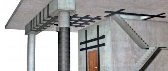
Crossbars connect the vertical structural elements of structures, themselves serving as supports for floor slabs. This function contributes to the formation of rigid spatial strength of the building’s reinforcement, united by welding. Such structures guarantee geometric stabilization of the structure as a whole, transferring the weight of horizontal structures to the supporting vertical “skeleton” of the building. A belt made from such products is capable of raising the base above the foundation to the required height, strengthening and relieving the latter. They are used to assemble structures with wide spans of premises (hangars, trading floors), and to strengthen columns in rooms with high ceilings.
These members are designed to withstand significant loads when laid as beams or used as columns. Reinforced concrete crossbars can be used to form window commissures and fences in multi-storey buildings. In the construction of high-rise buildings and in structures of especially large dimensions, a modification of the crossbar is used, which has a length of 12 m.
This variety has proven to be more reliable than steel samples. Transport infrastructure (fences, parapets, passages, viaducts, bridges, etc.) is actively being constructed using crossbars. In the energy sector, products are used to increase the area of the load-bearing base of power transmission line masts, which allows for horizontal distribution of loads to increase the bearing capacity of the supports.
Return to contents
What is a deadbolt
The crossbar connects vertical structures into one system.
Purpose
The product is mounted so that there is a horizontal connection between the columns. Floor slabs and sheathing rest on it.
The element absorbs a vertically applied load and distributes it evenly across the columns. Sometimes used for formwork system.
Difference from beam
To understand the difference between these two elements, you need to know what they are used for. The crossbar is a product with narrowly targeted applications. The beam, on the contrary, is widely used in construction. Mostly they work on bending. They can be positioned vertically, horizontally, or at an angle. In addition, they absorb small loads, for example from window or door openings, and their weight is less.
While the crossbars perceive significant support loads, i.e. are load-bearing elements. More powerful reinforcing bars are placed in them (if they are made of reinforced concrete). These products have great strength and rigidity.
The crossbar is a load-bearing element.
The crossbars are located only horizontally in the building. There are times when beams rest on them. You cannot replace one element with another.
Scope of application
Modular and frame structures are now gaining popularity. This is due to the desire of customers to save money and reduce costs. In addition to being used in residential buildings and industrial buildings, crossbars are used:
- for the construction of staircases and landings;
- for the construction of fences, window openings;
- during the construction of buildings with high ceilings;
- during the construction of power lines;
- for formwork;
- in individual housing construction;
- for the construction of bridges, arched spans.
Peculiarities
Their designs have different profiles, dimensions (length, cross-section), material, and method of fastening, which is determined by the specific location of application. The cross-sectional shape of the samples is a brand with one or two shelves (for floor slabs), as well as a rectangle and a T-shaped without shelves. The option with one shelf allows you to support slabs on one side (flight of stairs, end bay of a building).
A model with two shelves is supported by two slabs (typical for central spans). T-shaped modifications with a low shelf reduce the visible exit of the structure body into the premises. On rectangular crossbars, the load is simply placed on top. The structural features and purposes of buildings require the use of rigid or hinged methods of fastening crossbars.
Return to contents
Shapes and sizes
There are 3 types of crossbars in shape:
- with 1 shelf;
- rectangular (shelfless);
- with 2 shelves.
The first ones are placed at the edges of the building. The slabs can rest on them only on one side. With 2 shelves, the products can be installed in the center of the building so that the floors can be stacked on both sides. Main dimensions for reinforced concrete crossbars:
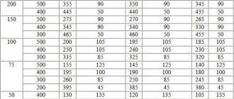
- length from 2560 mm to 8560 mm;
- sections from 450*230*565 to 600*300*595.
The ceilings are laid on both sides.
There are cross-sectional dimensions from 450*230*482 to 600*230*497. For certain categories of buildings, elements with a length of 11200 mm are manufactured. The cross-section of such products is 800*300*550*400 (with 2 shelves). Such structures are used in industrial buildings, where columns are placed at intervals of 12 m and large spans need to be covered.
Marking
Products are marked with a alphanumeric code, separated by a dash into groups. Example - RDP 6.56-110AIV. 1st group indicates the type of crossbar, its height in diameter and length (dm), rounded to whole numbers. It is permitted to replace the contents of this group with the name of the product - deadbolt (“P”) indicating the standardized standard size. The second one provides information about the load-bearing capacity (in kN/m) of the product or its serial number in terms of load-bearing capacity. Next, for prestressed reinforcement, the steel class is indicated (Latin letter and Roman numeral).
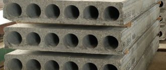
Thus, the RDP 6.56-110AIV marking on the product says: RDP type - crossbar for reinforced concrete hollow-core slabs, height 6 dm (600 mm), length 56 dm (5560 mm), load-bearing capacity 110 kN/m, class A-IV steel is laid inside. In some cases, a third group of designations is used, characterizing the special conditions in which the product can be used. This applies, for example, to resistance to aggressive gases and seismic shocks. The installation of additional embedded parts can also be taken into account.
Products marked RDP 6.56-110AIV-Na, for example, in the 3rd group indicate that the material of the product is concrete with normal (“N”) permeability (allowed for use in mildly aggressive gaseous environments), inside which additional embedded elements (“ A"). Crossbars by type are designated by letters: R - rectangular, RO - single-shelf (ROP - for hollow-core slabs, RLP - for flights of stairs, ROP - for ribbed slabs, RLR - similar to RLP), RB - shelfless in the form of the letter "T" (RBP - for hollow-core slabs, RBR - for ribbed slabs), RD - two-shelf (RDP - for reinforced concrete hollow-core slabs, RDR - for ribbed slabs) and RKP - balcony (cantilever) for hollow-core slabs. There are crossbars with the manufacturer's abbreviation (according to specifications), taking into account the specifics of their shape, for example, РВ, РМ, AR, etc.
Return to contents
What is the crossbar made of?
Products of this type are made from heavy concrete of class B 22.5 to B 60. The output is crossbars, the strength of which is at least 75% in the warm season and about 85% in cold conditions. In addition, the roof beam must be waterproof, fire-resistant, frost-resistant, and not susceptible to aggressive environments and corrosion.
Since this type of structure must be highly durable, reinforcement is used in the production process. The crossbar reinforcement is made from steel reinforcement frames of the highest class: hot-rolled and reinforced by thermomechanical processing.
When producing these building elements, it is imperative to take into account GOST 18980-90, which specifies strict requirements. Moreover, any discrepancies with the standards can greatly affect the strength characteristics of the entire structure.
The possibility of its use in a particular area will depend on the quality of the manufactured structure.
The difference between a crossbar and a beam
From an etymological point of view, a beam is a broader concept, and a crossbar is the same beam, but performing a highly specialized function.
The crossbar can be considered a horizontal beam with special load-bearing functions (accepts loads from any direction) as the main supporting element of the building frame. It is a horizontal part of the frame, which is rigidly connected to the vertical posts of the main supporting structure (not subject to calculation). A beam laid horizontally or at an angle works as an independent structural unit of the structure's frame, only mainly for bending (calculated during design). Crossbars and beams cannot be interchanged, since the former are monolithic (reinforced concrete or metal) and have great weight, rigidity and strength, while the latter, as a rule, having a small mass, are made of wood or hollow metal structures.
The functionality of the crossbars is quite narrow, but the scope of application is significant. The purpose of the reinforced concrete crossbar is clearly defined and, regardless of the conditions, remains unchanged. Whereas the definition of “beam” itself is broad, including a crossbar. Beams are used in the construction industry in the form of floors or their support (an example is an attic, the main function of which is to distribute the load of beams with rafters onto crossbars), as well as coverings.
Return to contents
Which transom is better: with or without concrete?
Reinforced concrete products are often subject to negative impacts. This could be frost, precipitation, high humidity or temperature. These factors negatively affect the characteristics of reinforced concrete products during operation.
When constructing structures, in particular large industrial workshops, it is important to ensure the rigidity and strength of the building. Therefore, structures require protection. The negative impact can be reduced by using special compounds that are added to the concrete mixture. They increase resistance to frost, strength, increase ductility and fluidity. Therefore, the addition of special concrete improves the performance characteristics of the crossbars.
How to make a crossbar?
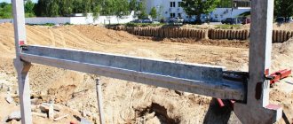
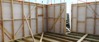
Installation of formwork.
It is possible to cast reinforced concrete beams directly on the construction site. A heavy monolithic product should not form a frame in wooden or frame buildings. Its use will require more careful calculation of the strength of the foundation. At the preparatory stage, a strong formwork is created that specifies the correct, precise geometric dimensions and shape with stiffeners. Metal sheets (boards) are used to form the bottom of the mold, and thick moisture-resistant plywood is used for the sides.
The form is installed on T-shaped supports made of boards and horizontalized. Its bottom and inner walls are carefully covered with roofing felt (film). The length and loads on the reinforced concrete structure determine the number of reinforcement frames (upper, lower) formed in the crossbar. The height of the lower edge of the lower frame above the bottom is at least 3 cm, and the upper edge should be located 3 cm below the level of the upper cut of the form. Reinforcing frames are formed outside the mold and then installed into it.
The bottom reinforcement is made continuous and laid longitudinally (takes a tensile load), its diameter is at least 1 cm. The frames are scalded (knitted with wire). The lower longitudinal reinforcement is not joined in the central third of the length, and the upper one is not joined at the extreme quarters of the length. Concrete mortar is mixed from parts of crushed stone, sand, cement in a ratio of 4/2/1 and water. The pouring is done continuously, the mixture is compacted with a vibrator. Maintenance of the concrete product for the first 7–10 days is carried out according to the season.
The side panels are removed after 2 weeks, the lower support of the crossbar is retained until the end of 28 days. Then the quality of the concrete is checked instrumentally. If the result is positive, the crossbar is loaded after full strength has been achieved.
Return to contents
Installation of crossbars
In order to install the load-bearing element, you will need a crane and slings. It has special metal loops called mounting loops. When erecting frame structures, the installation of products begins from the lower tier (sometimes this is the basement), then gradually moves to the upper sections.
The structures are supported by column consoles, special tables, and reinforced concrete pillows. For accurate installation, it is necessary to align the axis of the horizontal element and the column. The support areas must be the same on both sides so that the product is located strictly in the center. After adjusting and checking the position, the joints are welded. Then, to achieve a monolithic structure, the interface unit is filled with concrete mixture.