The installation of a strip foundation can be divided into a number of project stages:
- tying the foundation to the boundaries of the site and marking the axes of the log house
- excavation work - the main part of the belt is buried 1-1.2 meters below ground level; at the intersection of the axes, i.e. in the corners of the log house, we make additional depths to a depth of 1.8 meters below ground level, measuring 0.4 * 0.4 meters (maximum soil freezing in the middle zone according to SNiP is 1.65 meters). This is necessary so that in the spring, when the soil thaws, the foundation of your house or bathhouse does not deform.
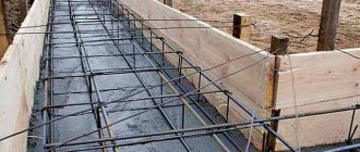
- arrangement of the spatial frame of the foundation body - the frame is connected into a single whole using binding wire and individual reinforcement rods. When constructing a frame, it is important to correctly reinforce the areas of the foundation that are most loaded and subject to large deformations.
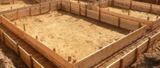
- production and installation of formwork panels from timber and edged boards; arrangement of technological holes
- leveling the foundation - using a leveling device, the level of the foundation horizon is marked, resulting in a perfectly flat plane on which the log house is installed.
- pouring concrete mixture into formwork
- dismantling of formwork panels
We carry out the entire list of work necessary to install a high-quality foundation for a log house, both a small bathhouse and any even complex house!
There are two ways to build a foundation:
- Our company performs only all of the above types of work, and the material for their implementation is supplied by the customer (the required amount of material will be calculated by our company). In this case, the cost of the work will be 2,500 rubles. for 1m3 of foundation.
- Our company searches for material for work, delivers it, unloads it on site, and performs all types of work necessary for constructing the foundation. In this case, the cost of work including materials will be 8,500 rubles. for 1m3 of foundation.
Optimal distance for various buildings
You cannot rely only on the size or purpose of buildings, since in addition to the weight of the house, the type of soil plays an important role.
The denser the underlying layers, the smaller the width of the tape can be made during construction.
For auxiliary and utility buildings, the width of the tape is allowed:
- Dense (rocky) soil, clay - 25 cm.
- Loam - 30 cm.
- Sand, sandy loam - 35 cm.
- Soft compacted sand - 40 cm.
- Very soft sand - 45 cm.
For one-story light houses (dacha, frame house):
- Dense (rocky) soil, clay - 30 cm.
- Loam - 35 cm.
- Sand, sandy loam - 40 cm.
- Soft compacted sand - 45 cm.
- Very soft sand - 50 cm.
For two-story cottages:
- Dense soil - 50 cm.
- Loam - 60 cm.
- Other types of soils do not have average indicators and require separate specialized calculations.
It must be borne in mind that average values are rarely suitable for specific situations, since there are always a lot of additional factors not taken into account in the tables.
The impact of these factors can radically change operating conditions and require a separate calculation, sometimes made using a completely different methodology.
What should be the height of the foundation above the ground?
The construction of most types of foundations for a frame or brick house requires the presence of an above-ground part. Its main purpose is to provide protection from precipitation and temperature fluctuations of the load-bearing part of the structure, which is located underground. How tall should it be? On the one hand, it is logical to increase the above-ground part in order to also protect the house itself, but on the other hand, doing this will be expensive from a financial point of view.
It is recommended to install a strip foundation made of blocks or bricks or slabs for a frame or stone house with an elevation from the ground surface of more than 30 cm. Such a device will visually clearly separate the building from the foundation and improve the integrity of the object when operating under the negative influence of the external environment.
This fact must be taken into account and the appropriate dimensions must be applied to the drawing of the house using reliable data for a specific region of development. To simplify the task, you can look at ready-made house designs that were built nearby. But it is still recommended to double-check the accuracy of the calculations.
We recommend watching a video about how deep to dig a strip base.
When building a frame house, they usually try to save on the foundation and make it from timber. However, to provide additional protection against freezing and heaving of the soil, the height is made much higher than when laying a foundation made of blocks. The maximum permissible length is 30-40% of the total length of the piles, depending on the presence of compressive and tensile stresses in the soil, so that the foundation is not flooded with water.
If you plan to build a house from timber or brick on a foundation made of blocks or a monolith, then the calculation must be carried out taking into account the factor of soil subsidence under heavy load. In such cases, it is necessary to provide a reserve of approximately 20-30% of the value taken taking into account the amount of precipitation. This will allow you to effectively deal with heaving and loose soils, as well as seasonal soil movements.
Pile
The load-bearing part of the base is screw piles. They are placed in areas of greatest load, as well as at the corners of the building, under the intersections of walls and partitions. Piles can be located at equal intervals over the entire base area.
A pile is a steel rod with a point or screw at the end. It is driven or screwed into the ground. The length of the piles (and their depth) can be very large, up to several tens of meters. This allows you to build even on unstable, difficult soils. After installing the piles, their upper parts are connected to each other with a grillage or metal structures, creating a foundation on which the house is built.
Advantages: fast construction, reliability, versatility. No excavation required.
Disadvantages: complex, expensive technology, requires special equipment.
Pile foundations are used for heavy loads: for the construction of multi-story buildings, industrial complexes, and large-sized objects. Even in difficult conditions they have high reliability and ensure effective load distribution.
Pile foundations can be used in low-rise construction for houses made of any materials. There are several technologies, both with the use of steel pipes or rods, and with the installation of bored piles. The latter are shaft-wells in the ground with a bottom below the freezing depth, filled with reinforced concrete.
Calculation of the foundation depth of a one-story house
Trench under the base
The foundation for a one-story house must be laid at a depth that is below the freezing level of the soil. The drawing must take into account this criterion and is made taking it into account.
The normalized freezing depth is determined based on data obtained over the last 10 years for a specific region. The observation results are compared with GOST 25100, and then the line of transition of plastic frozen soil into solid soil is determined.
If there is no access to such data or they are lost, then for regions with a freezing depth of up to 2.5 m it is permissible to perform the calculation using the formula:
where Mt is a dimensionless coefficient, which is determined by the sum of all absolute temperature values below zero, according to SNiP 23-01. If there is no information on temperatures in regulatory documents, then you must contact the hydrometeorological center to obtain them;
d0 is a value depending on the type of soil in the area. You can take it from SP 22.13330.2011.
If the freezing depth exceeds 2.5 m, then thermal calculations must be carried out in accordance with SP 25.13330. Calculation of seasonal soil freezing is carried out using the formula:
where kh is a dimensionless coefficient that takes into account the thermal regime for external and internal foundation structures based on information about the heating of the building. Determined according to Table 1 or taken equal to 1.1 for unheated premises (with the exception of the northern regions, where negative temperatures prevail throughout the year).
Table 1. The value of the kh coefficient depending on the design features of the building
The data in Table 1 is valid for those cases when the distance between the wall and the edge of the foundation is less than half a meter, and if it is exceeded, the coefficients should be increased by 0.1. If the temperature falls within the interval between the table values, then take the value with the lower value.
The depth of laying the external or internal foundation for heated rooms with cold basements or technical rooms should be determined based on Table 2.
Table 2. Foundation depth depending on the type of soil for houses with an unheated basement
Calculation of the foundation depth for a house made of blocks or bricks with a basement is carried out using the following formula:
where hs is the thickness of the soil above the base as viewed from the basement;
hcf – basement floor thickness;
γcf – value of the specific gravity of the basement floor structure.
Watch the video on how to make your own base scale.
Standards
When designing and constructing a foundation, engineers comply with the requirements of a number of basic standards:
- SNiP 2.02.01-83 (SP 22.13330.2010). “Foundations of buildings and structures” is the main document that describes the requirements for the design of foundations in different conditions;
- SNiP 3.03.01-87 (SP 70.13330.2011). Describes the requirements for materials, standards for foundation construction;
- SNiP 2.01.07-85 (SP 20.13330.2011). Loads and impacts. Contains data on possible loads, their combinations, the impact on building structures, and is used in the calculation part of the design.
Do you have questions about arranging the foundation? We will call you back
or call the number
Clicking the "Submit"
, you automatically consent to the processing of your personal data and accept the terms of the User Agreement.
An example of independent calculation of the width of a strip foundation
To better understand how to calculate the width of a monolithic tape, you need to consider this with an example. Initially, you need to systematize the initial data necessary for the calculation.
- size of the house in plan – 10 m x 10 m. Building area – 100 m 2;
- inside the house there is a load-bearing wall in the middle;
- the walls are brick, 1 brick thick - 250 mm and 2.7 m high. The specific gravity of the brickwork is 1600 kg/m 3;
- slate roofing – 40 kg/m2;
- flooring made of reinforced concrete slabs - 500 kg/m2;
- soil freezing depth – 700 mm;
- groundwater level – 2.2 m;
- soil base – dry loam of medium density with a design resistance of 2 kg/cm2;
- snow load – 50 kg/m2;
- payload – 20 kg/m2.
Determination of the total load from the house on a strip monolithic foundation
Based on the available initial data, the total load on the foundation is calculated. The dimensions of the monolithic tape are also determined. It is necessary for developers to make calculations in the following order:
Roof
The roof is made of slate and has a gable roof. Taking into account the slope of the roof and its overhangs, a coefficient of 1.1 is used. The load from the roof will be: 100 m 2 x 1.1 x 40 kg/m 2 = 4000 kg.
Brick walls
To determine the load from the walls, knowing their thickness, you need to calculate their length. The length of the walls along the perimeter will be: (10 x 4) – (0.25 x 4) = 39 m. The deduction of the double thickness of the brickwork is made because the axes of the house plan are drawn in the middle of the thickness of the walls. The length of the internal load-bearing wall will be 10 - 0.25 = 9.75 m. The total length of the load-bearing walls will be equal to 48.75 running meters.
The volume of brickwork will be: 48.75 x 0.25 x 2.7 = 32.9 m3. The total load from the brick walls is: 32.9 x 1600 = 52,670 kg.
Flooring made of reinforced concrete slabs
The one-story house has ceilings on two levels. This is the ceiling of the basement and the ceiling in the house. The floor area is: 100 x 2 = 200 m 2. Accordingly, the load from the floor slabs will be equal to: 200 m 2 x 500 kg/m 2 = 100,000 kg.
Snow load
To calculate the snow load, take the total roof area of the house - 100 x 1.1 = 110 m2. The snow load will be: 110 m 2 x 50 kg/m 2 = 5,500 kg.
Payload
The rate of this load is calculated based on the average weight of technical equipment, internal communications, room decoration, furniture and other things. The specific weight of the payload ranges from 18 to 22 kg/m2.
The payload is calculated on the basis of an average of 20 kg/m2. The weight will be: 100 m 2 x 20 kg/m 2 = 2000 kg.
In total, the total load on the foundation will be equal to: 4,000 + 52,670 + 100,000 +2,000 = 159,000 kg.
Calculation of the width of a monolithic tape
According to the above formula, the minimum area of the foundation base is determined:
(1.2 x 159,000 kg): 2 kg/cm 2 = 95,400 cm 2. That is, the minimum allowable area of the base of the house will be 10 m2.
The total supporting area of brick walls is determined by the product of the plan length of the load-bearing walls and their thickness: 48.75 m x 0.25 m = 12.18 m 2.
The result shows that the calculated support area is less than the minimum support area of the walls. Therefore, the width of the strip foundation should be equal to 250 mm + 100 mm = 350 mm.
Requirement for materials for the construction of a monolithic tape
Taking into account the thickness of soil freezing (0.7 m) and the depth of the groundwater level (2.2 m), the monolithic tape is made shallowly buried - 1 m.
To fill the formwork, concrete M 300 is used. The volume of need for concrete solution is equal to: 0.35 m x 1 m x 48.75 m = 17 m 3. . Taking into account unforeseen losses, the need for concrete will be 17.3 m 3.
The reinforcement frame consists of 4 longitudinal reinforcing bars of a periodic profile with a diameter of 12 mm. Since the transverse rods of the frame are made from the same rods, the total need for reinforcement will be: 50 m x 4 = 200 m.
From all of the above, we can conclude that it is quite possible for people who are more or less knowledgeable in the construction business to calculate the width, height and length of the strip foundation for their home.
How are site conditions affected?
The foundation is a supporting structure that takes the weight of the building and distributes the loads associated with it. It should be smooth, rigid, and strong enough. The foundation rests on the ground. To prevent its deformation, it is important that the soil does not sag or settle. To do this, when calculating the structure, the characteristics of the soil and expected loads are taken into account. In practice, complex geology, insufficient bearing capacity of the soil or its heterogeneous composition almost always mean higher construction costs and the need to make a more complex and expensive foundation.
For the design and construction of the building’s foundation, the following site parameters are important:
- Bearing capacity of the soil. It is determined by the structure of the soil and its composition. It is important to carry out surveys to a sufficiently large depth, taking into account the “zone of influence” of the foundation, which is always greater than the depth of its foundation. If the construction of a heavy building is planned, there should be no weak soil in this zone of influence;
- Freezing depth. In the Moscow region it is 1.5 m. Even when constructing light buildings, the foundation is laid to a great depth to prevent frost heaving. The exception is shallow foundations;
- Ground water level. Humidity reduces the strength of the soil. Contact with groundwater can cause concrete to deteriorate. To lower the groundwater level, you need ring or wall drainage. In the Moscow region, the organization of drainage is necessary for almost all development areas;
- Relief. If the site has a slope, a more complex and massive foundation will be needed.
Peculiarities
Advantages:
1. Increased load-bearing capacity. A monolithic slab creates a slight pressure on the ground due to the uniform distribution of the entire load, regardless of the thickness of the fill. An excellent option for a house made of timber, cellular concrete, even brick.
2. Spatial rigidity. This eliminates the possibility of subsidence in certain areas (for example, a tape) and the appearance of cracks in concrete, on walls or loose joints.
3. Versatility in application. A slab foundation is suitable for any soil, including those called problematic.
4. Simplified construction technology. The construction of a monolithic slab does not require extensive excavation work, which significantly saves time.
5. Possibility of high-quality insulation. Options - laying polystyrene foam under the base, introducing special additives into the solution.
6. Reduced concrete consumption. Although this is only true for cases of arranging a non-buried monolithic slab.
Flaws:
Many of them are relative, but they are worth noting.
1. Complexity of calculations. This concerns the thickness of the future slab. If we are talking about a building with a basement, then it is better to choose a different foundation option. Firstly, the cost of construction will increase sharply. Secondly, calculations for a monolithic slab will become significantly more complicated.
2. High costs. Here a lot depends on the specific scheme, but it is undeniable that with such construction savings are achieved on other materials. If the slab foundation is shallow and of small thickness, it can be impressive.
3. Labor intensity. The question is how well the construction work is organized. For example, using an “automixer” greatly simplifies the technology of pouring concrete mortar and saves time. The same applies to the accuracy of calculations of the thickness of a monolithic foundation.
4. Certain difficulties with individual projects. First of all, when implementing a scheme with a basement and during construction on relief soil.
Calculation of slab thickness
It is appropriate to provide only general instructions and recommendations, since much depends on the specifics of construction - the characteristics of the soil, the number of storeys of the house, the materials from which it is built, and a number of other nuances.
Initial data for calculating the thickness of the foundation:
- Soil type.
- Configuration of underground aquifers.
- Soil freezing level.
- The presence of a drainage system on the site and its layout (if installed).
- Total load on the foundation.
What is determined:
1. Thickness of concrete reinforcement elements (rod, mesh).
2. The size of the reinforcement cells and the interval between its layers in the monolith.
3. The distance of the rod from the upper and lower cut of the foundation.
The difference in this foundation parameter for buildings of the same type can be significant. For example, the thickness of a slab for a wooden house varies quite widely and depends precisely on the characteristics of the soil, although it is a relatively light structure of 1-2 floors.
*Dimensions – in “mm”.
- The cross-section of the rod is 12.
- 2 levels of reinforcement, the interval between which is 70.
- The distance between the reinforcement and the sections of the concrete monolith is 50.
Calculation: 12 x 2 + 70 + 50 x 2 = 194.
Rounded - 20 cm. For example, this is the minimum thickness of a slab for a house made of aerated concrete. But subject to the construction of a shallow monolithic foundation on good, dense soil. That is why it is advisable to entrust all calculations to a professional.
Construction of foundations
Foundations are the supporting part of the building and are designed to transfer the load from the structures above to the base.
The foundations of the building must satisfy the following basic requirements: have sufficient strength and stability against overturning and sliding in the plane of the sole, resist the influence of atmospheric factors (frost resistance), as well as the influence of ground and aggressive waters, correspond in durability to the service life of the building, be economical and industrial in production .
Having laid out a place for the foundation of the building, they begin to excavate the soil. It is recommended that the construction of the foundation be carried out immediately after excavation. When the soil in the trench dries out, it crumbles and it takes a lot of time to remove it.
By design, foundations are divided into: solid, strip, columnar and pile.
Solid foundations
They are a continuous block-free or ribbed reinforced concrete slab under the entire area of the building. Solid foundations are used in cases where the load transferred to the foundation is significant and the foundation soil is weak. This design is especially appropriate when it is necessary to protect the basement from the penetration of groundwater at high levels, if the basement floor is subjected to high hydrostatic pressure from below.
Rice. 1 Solid beamless foundation:
1 - reinforced concrete foundation slab
There are foundation designs in the form of reinforced concrete monolithic slabs, which can be beamless or ribbed.
Rice. 2. Solid reinforced concrete foundation slab: a - beamless; b - ribbed
Strip foundations
They are installed under the walls of a building or under a number of individual supports. In the first case, the foundations have the form of continuous underground walls (Fig. 3 a), in the second - reinforced concrete cross beams (Fig. 3 b).
According to its outline in profile, the strip foundation under a stone wall is, in the simplest case, a rectangle (Fig. 4d). A rectangular cross-section of the foundation in height is permissible only with small loads on the foundation and a sufficiently high bearing capacity of the soil.
In most cases, to transfer pressure to the foundation that does not exceed the standard pressure on the ground, it is necessary to expand the base of the foundation. The theoretical cross-sectional shape of a foundation with an expanded base is a trapezoid (Fig. 46). The expansion of the base should not be too large to avoid the appearance of tensile and shear stresses in the protruding parts of the foundation and the appearance of cracks in them.
Rice. 3. Foundation designs:
a - foundation in the form of continuous underground walls: 1 - strip foundation; 2—wall; b—in the form of crossed reinforced concrete beams: I—strip foundation for columns; 2 - reinforced concrete column
Based on experience, the angles of inclination of the theoretical side face of the foundation to the vertical have been established, along which dangerous tensile and shearing stresses do not occur. The limiting angle, conventionally called the angle of pressure distribution in the foundation material, is 45° for concrete, 33° 30′ for masonry with a cement mortar of composition 1:4, and 26° 30′ for rubble masonry with a complex mortar of 1:1:9 composition.
In buildings with basements, the cross-section of the foundation within the basement is arranged in a rectangular shape with an extension below the basement floor, called a pillow (Fig. 5 a). Often foundations are made with a stepped section (Fig. 5 b).
The depth of the foundation must correspond to the depth of the soil layer, which, due to its qualities, can be accepted as a natural foundation for a given building. When determining the depth of the foundation, it is necessary to take into account the depth of soil freezing. It is recommended to lay foundations below the freezing depth. If the base consists of moist fine-grained soil (silty or fine sand, sandy loam, loam, clay), then the base of the foundation is placed no higher than the freezing level of the soil.
The level of soil freezing is taken at a depth where the temperature is 0°C in winter, with the exception of clay and loamy soils, for which the freezing level is taken at a shallower depth, where the temperature is about -1°C.
The standard freezing depth for loamy and clayey soils is indicated in SNiP 2.02.01-83 on a schematic map in which lines of the same standard freezing depths, expressed in centimeters, are plotted. The standard freezing depth for silty and fine sands, sandy loams, silty clays and loams is also taken from the map, but with a coefficient of 1.2.
Fig. 4. Strip foundations: a — rectangular; b - trapezoidal: 1 - edge
Fig 5. Strip foundations:
a - rectangular with a pillow; b - stepped with pillow (1)
Research has established that the soil under the foundations of the external walls of regularly heated buildings with a room temperature of at least +10° C freezes to a shallower depth than in an open area. Therefore, the calculated freezing depth under the foundations of a heated building is reduced against the standard value by 30% for floors on the ground; if the floors are on the ground on joists - by 20%; floors laid on beams - by 10%.
The depth of the foundation for the internal walls of heated buildings does not depend on the depth of soil freezing; it is set at least 0.5 m from the basement floor or ground level.
The depth of laying the foundations of the walls of buildings with unheated basements is determined from the basement floor; it is equal to half the calculated freezing depth. The assumption that the deeper the foundation is laid, the greater its stability and reliability, is incorrect.
When the base of the foundation is located below the level of soil freezing, the vertical forces of frost heaving cease to act on it from below, but the tangential forces of frost heaving acting on the side surfaces can pull out the foundation along with the frozen soil, and tear it off under light buildings when constructing foundations made of bricks and small blocks.
Therefore, for successful operation of the foundation, in order to prevent its deformation in heaving areas, it is necessary not only to place the base below the soil freezing level, which will relieve the direct pressure of frozen soil from below, but also to neutralize the tangential forces of frost heaving acting on the side surfaces of the foundation. Inside the foundation, a reinforcement frame is laid over its entire height, rigidly connecting the upper and lower parts of the foundation; the base is made expanded in the form of a support platform—an anchor, which does not allow the foundation to be pulled out of the ground during frost heaving of the soil. This design solution is possible using reinforced concrete.
When constructing a foundation of brick or small blocks, without internal vertical reinforcement, the walls are made inclined—tapering upward. The above method of constructing foundation pillars and walls, with careful alignment of their surfaces, significantly weakens the lateral vertical impact of heaving soils on the foundation. The influence of frost heaving forces is reduced by: covering the side surfaces of the foundation with a sliding layer of polyethylene film; used machine oil; insulation of the surface layer of the soil/around the foundation with slag, polystyrene foam, expanded clay, which reduces the local freezing depth of the soil. The latter is also applicable for shallow foundations built earlier and in need of protection from frost heaving.
On large falling terrain, when constructing a building, it is necessary to take into account the lateral pressure of the soil and its probable shift. Strip foundations rigidly connected in the longitudinal and transverse directions work more reliably under these conditions. Columnar foundations must be rigidly united on top with a reinforced concrete belt - a grillage, for more efficient collaboration of all structural elements. In gravelly, large and medium-sized sands, as well as in coarse-grained soils, the depth of the foundation does not depend on the depth of freezing, but it must be at least 0.5 m, based on the natural level of the soil (the planning mark when planning by cutting and filling).
In modern construction, the most industrial types are prefabricated concrete and reinforced concrete foundations made from large foundation blocks. The use of prefabricated foundations can significantly reduce construction time and reduce the labor intensity of work. The prefabricated foundation (Fig. 6) consists of two elements: a cushion made of reinforced concrete blocks of rectangular or trapezoidal shape (Fig. 7) laid on a carefully compacted sand preparation 150 mm thick, and a vertical wall made of blocks in the form of concrete rectangular parallelepipeds.
Rice. 6. Prefabricated strip foundation made of concrete blocks for the walls of a house with a basement and technical underground:
I— foundation slab; 2 - concrete wall blocks; 3 — painting with hot bitumen; 4 - cement-sand mortar; 5 - blind area; b - two layers of roofing felt or hydronzol on bitumen mastic; 7 - basement floor
Rice. 7. Foundation block-pillow
When building on weak, highly compressible soils, in prefabricated foundations, to increase resistance to tensile forces and rigidity, reinforced concrete belts with a thickness of 100-150 mm or reinforced seams with a thickness of 30-50 mm are installed, placing them between the cushion and the bottom row of foundation blocks, as well as at the level of the top foundation cuttings.
Foundation walls, mounted from large blocks, despite their greater strength, are sometimes built thicker than the above-ground part of the walls. As a result, only 15-20% of the material's strength is used. Calculations show that the thickness of the walls of prefabricated foundations can be taken equal to the thickness of the above-ground walls, but not less than 300 mm.
Savings in building materials can be achieved by installing intermittent foundations consisting of reinforced concrete blocks-pillows, not laid closely, as is provided for in strip foundations, but at a certain distance from one another, approximately from 0.2 to 0.9 m. The gaps between blocks are covered with soil.
Columnar foundations
They take the form of separate supports placed under walls, pillars or columns. With insignificant loads on the foundation, when the pressure on the ground is less than the normative one, it is advisable to replace continuous strip foundations under the walls of low-rise buildings with columnar ones. Foundation pillars made of concrete or reinforced concrete are covered with reinforced concrete foundation beams on which the wall is erected. To eliminate the possibility of the foundation beam bulging due to swelling of the soil located underneath it, a sand or slag cushion 0.5 m thick is placed under it.
The distance between the axes of the foundation pillars is taken to be 2.5-3 m. The pillars must be placed at the corners of the building, at the intersections and junctions of walls and under piers.
Columnar foundations for walls are also erected in high-rise buildings with a significant foundation depth - 4-5 m, when the installation of a continuous strip foundation is unprofitable due to its large volume and, consequently, greater consumption of materials. The pillars are covered with prefabricated reinforced concrete beams, on which the walls are erected. Columnar single foundations are also used for individual building supports. Figure 8a shows a prefabricated foundation for a brick pillar made of reinforced concrete cushion blocks. A more economical option is to lay reinforced concrete block slabs under the brick pillars (Fig. 8 b). Prefabricated foundations for reinforced concrete columns of frame buildings can consist of one glass-type reinforced concrete shoe (Fig. 8c) or a reinforced concrete glass block and a base plate under it (Fig. 8d).
Pile foundations
They consist of individual piles united on top by a concrete or reinforced concrete slab or beam called a grillage (Fig. 9). Pile foundations are used in cases where it is necessary to transfer significant loads to weak soil.
Fig. 8. Prefabricated foundations for individual supports: a - for brick pillars made from strip foundation blocks; b - the same, from special reinforced concrete slabs; c — under a reinforced concrete column made of a glass-type shoe; g - the same, from a glass block and a base plate
Piles are differentiated by material, method of manufacture and immersion in the ground, and the nature of work in the ground. According to the material, piles can be wooden, concrete, reinforced concrete, steel and combined. According to the method of manufacturing and immersion into the ground, piles can be driven, immersed in the ground in finished form, and driven, manufactured directly in the ground. Depending on the nature of the work in the ground, two types of piles are distinguished: rack piles and hanging piles. Rack piles rest with their ends on solid soil, for example, rock, and transfer the load to it (Fig. 10). They are used when the depth of solid soil does not exceed the possible length of the pile. Pile foundations on rack piles provide virtually no settlement.
If strong soil is located at a significant depth, hanging piles are used, the bearing capacity of which is determined by the sum of the resistance of friction forces on the lateral surface and the soil under the tip of the pile (Fig. 11).
Rice. 9. Types of piles in the ground:
a - hanging piles; b— rack piles: 1 — dense limestone; 2—plastic silty loam; 3 - silt; 4 - silty sand; 5 - peat; 6 - plant layer
Wooden piles are cheap, but because they rot quickly if placed in soil with variable moisture content, the heads of the wood piles should be located below the lowest water table. However, in areas with high groundwater levels, wooden piles last a very long time if they are constantly in water. In world practice, there are examples of four-hundred-year-old buildings on wooden stilts that are still in good technical condition.
Reinforced concrete piles are durable, more expensive than wooden ones, but can withstand significant loads. The scope of their application has been significantly expanded due to the fact that the design elevation of the heads of reinforced concrete piles does not depend on the groundwater level. The distance between the axes of the piles is determined by calculation. Within the most common immersion depths of piles - from 5 to 20 m, these distances for ordinary pile diameters range from 3...8d, where d is the diameter of the pile.
Fig. 10. Driven foundation pile: I - waterproofing; 2 - surface of the earth; 3 - reinforced concrete grillage beam; 4 - driven pile of rectangular section; 5 - dense soil
Rice. 11. Cast-in-place suspended pile foundation: 1 - waterproofing; 2 - reinforced concrete grillage beam; 3 - cast-in-place pile; 4 — casing pipe tip; 5—weak soils
Pile foundations, compared to block foundations, give less settlement, thereby reducing the likelihood of uneven soil deformations.
When preparing the foundation, sometimes old filled-in wells, holes, and random weak layers of soil are found in the soil. To avoid uneven settlement of foundations, these places must be cleared and filled with masonry, lean concrete or compacted sand, and when building foundations above these places, reinforced seams should be applied.
Foundations are moistened by atmospheric moisture or groundwater seeping through the soil. Due to capillarity, moisture rises through the foundation and dampness appears in the walls of the first floor. To block the penetration of moisture into the walls, an insulating layer is placed in their lower part, most often from two layers of bitumen roll materials (roofing felt, etc.), glued together with waterproof bitumen mastic. During the operation of foundations, it is necessary to monitor the settlement of the foundation and possible deformations.
Cellars
One of the important conditions for the safety and integrity of the house is waterproofing the basement. The walls and floors of basements, regardless of the location of groundwater, must be isolated from surface water seeping through the ground, as well as from capillary ground moisture rising upward. In basements, when the groundwater level is located below the basement floor, sufficient waterproofing of the floor is its concrete preparation and a waterproof floor made on it, and waterproofing of the walls is covering the surface in contact with the ground with two layers of hot bitumen. If the groundwater level is higher than the basement floor, in this case, the greater the difference in the levels of the floor and groundwater, the greater the water pressure created. In this regard, to waterproof the walls and floor of the basement, it is necessary to create a shell that can resist the effects of hydrostatic pressure.
An effective measure to combat the penetration of groundwater into the basement is the installation of drainage. The essence of the drainage device is as follows. Around the building, at a distance of 2-3 m from the foundation, ditches are arranged with a slope of 0.002--0.006 towards the prefabricated drainage ditch. Tubes (concrete* ceramic or others) are laid along the bottom of the ditches with a slope. There are holes in the walls of the tubes through which water penetrates.
Ditches with pipes are covered with a layer of coarse gravel, then with a layer of coarse sand and on top with open soil. Through pipes laid in ditches, water flows into the lowlands (ditch, ravine, river, etc.). As a result of drainage, the groundwater level decreases.
When the groundwater level is located no higher than 0.2 m from the basement floor, waterproofing of the floor and walls of the basement is arranged as follows. After coating the walls with bitumen, a clay castle is made, that is, before filling the trench, crumpled fat clay is driven close to the outer wall of the basement. The concrete floor preparation is also laid over a layer of crumpled fatty clay.
When the height of the groundwater level is from 0.2 to 0.5 m, adhesive waterproofing is used from two layers of roofing material on bitumen mastic (Fig. 12). The insulation is laid over a concrete floor preparation, the surface of which is leveled with a layer of cement mortar or asphalt.
Since the floor structure must withstand a fairly large hydrostatic pressure from below, a load layer of concrete is laid on top of the insulation, which balances the water pressure with its weight. On the outer side of the walls, insulation is glued with bitumen mastic and protected with a masonry of iron ore bricks of 1/2 brick with cement mortar and a layer of crumpled fatty clay 250 mm thick.
The adhesive insulation of the external walls of the basement is placed 0.5 m above the groundwater level, taking into account its possible fluctuations.
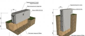
Figure 12. Waterproofing a strip foundation in a building with a basement:
1 - layer of load concrete; 2 - concrete preparation; 3 - roll waterproofing; 4 - crumpled fatty clay 250 mm; 5 - brickwork made of iron ore with cement mortar 120 mm; 6 - double layer of bitumen
Rice. 13. Waterproofing a strip foundation in a building with a basement:
1—concrete preparation; 2—reinforced concrete slab; 3-roll waterproofing; 4 - crumpled fatty clay 250 mm; 5 - brickwork made of iron ore with cement mortar 120 mm; b - double layer of bitumen
If the groundwater level is located more than 0.5 m above the basement floor, then a reinforced concrete slab is placed on top of the floor waterproofing, made of three layers of roofing felt or waterproofing material (Fig. 13). The slab is embedded in the basement wall, which, working in bending, absorbs the hydrostatic pressure of groundwater.
When the groundwater level is high, installing external waterproofing sometimes causes difficulties. In such cases, it is performed along the inner surface of the basement walls (Fig. 14). The hydrostatic pressure is absorbed by a special reinforced concrete structure - a caisson.
Rice. 14. Waterproofing the basement with high groundwater pressure;
1 - roll insulation; 2 - concrete preparation; 3 - cement layer; 4 - cement screed; 5 - reinforced concrete box-shaped structure; 6 - clean floor; 7 - cement plaster over bitumen coating; 8 - waterproofing
Necessary features that are taken into account during the construction of foundations and the construction of plinths
When laying foundations of any type, the following rules must be observed:
Most foundation structures use concrete. Concrete has the property of “maturing”, 28 - 30 days. After laying the concrete structure, it must be kept for a given time without loads and it is advisable to cover it with either roofing felt or other available material to prevent the top layer from drying out. While the concrete is setting, periodically water the foundation with water to prevent it from drying unevenly. So, building a house on a newly built foundation is fraught with danger; defects will not keep you waiting.
Waterproofing your foundation is important. It consists of coating the entire surface in contact with the ground with hot bitumen. The walls are also insulated. To do this, lay two layers of roofing felt (1st layer - between the base and the zero level; 2nd layer - between the base and the main wall of the house). This protects the walls of the house and the basement from dampness.
Protection of the outer side of the plinth from atmospheric influences. This is achieved by plastering or tiling. To grout the foundation, rubber-containing components (ash from burnt car tires) are added to the mixture. It turns out to be a “fur coat” for the base. She is beautiful and reliable.
When constructing the base, ventilation openings are provided. In summer they serve to ventilate the underground, and in winter they are closed to prevent dampness from entering the house.
The blind area is necessary to protect the foundation from the effects of surface water. The width of the blind area is from 0.75 to 1 meter with a slope from the base wall. The materials used are: reinforced concrete, asphalt, concrete or well-compacted clay.
The device for draining rainwater from roofs also affects the strength of the foundation. Rainwater from the roof falls on the blind area, breaks it and the base gradually, unevenly moistens the soil near the foundation. This affects the bearing capacity of the foundation and contributes to foundation subsidence.
How to calculate everything correctly
The formula for calculating the base area is as follows: S>γn F/γc R0, where
- γn—reliability factor equal to 1.2.
- F is the load on the base, i.e. the total weight of the house, foundation, snow load, weight of property, people, etc., affecting the underlying soil layers.
- γc is the operating conditions coefficient. Depending on the type of soil, it ranges from 1 (clay) to 1.4 (sand).
- R0 is the conditional soil resistance. The tabular value is in the SNiP annexes for this type of soil.
As a result of this calculation, the total area of the tape will be obtained. To determine the base width (average), the resulting value S must be divided by the total length of the tape, including internal walls and other areas of the perimeter. The resulting value will show the estimated thickness of the tape base.
This value is the minimum. In practice, it is increased, sometimes several times.
It should be noted that the given formula is given only to familiarize yourself with the calculation methodology. In any case, this work must be performed by a competent and experienced specialist. Calculating the foundation is an important and responsible procedure, which has a large number of difficulties and specific issues.
An unprepared person cannot calculate such a project without making a number of gross mistakes, which could result in the destruction of the house. Alternatively, you can use an online calculator, which allows you to obtain the parameters of the tape using known data (soil type, calculated or tabulated resistance values, etc.).
To clarify the data obtained, you should double-check the results obtained on other similar resources.
Concrete calculation
When calculating concrete, it is necessary to take into account:
- geometric dimensions of the base;
- brand of material used;
- the number of additional jumpers for installing load-bearing walls between rooms.
When calculating a concrete base, the diameter and number of reinforcement bars should be taken into account. The number and cross-section of iron elements are calculated in accordance with the rules of SP 52-101-2003; the durability and strength of the foundation and the entire building depend on the quality of the elements. After determining the geometric dimensions of the concrete fragments, the parameters of the formwork are determined. When making formwork from boards, you should take into account the thickness of the material, which must withstand the weight of the poured concrete solution.
There are 2 ways to determine the volume of concrete mixture for foundations:
- The developer can use automatic calculators, which record information about the total length of elements and cross sections. A separate field indicates the type of reinforcement used and the number of rods. The calculators take into account the type of foundation and allow you to enter information about additional structural elements (for example, the number and cross-section of stiffeners in a slab structure).
- To verify the obtained figures, a manual calculation technique is used.
Strip foundation
When calculating concrete for a foundation using the formula V=H*B*L*k, the following parameters are taken into account:
- H—total shaft height (m);
- B—belt width (m);
- L is the total length of the base (m);
- k - correction factor taking into account losses during transportation and filling, is taken equal to 1.05.
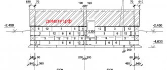
For example, when arranging a house measuring 8 * 8 m with an additional load-bearing wall, a tape 0.6 m wide is used, buried 1.8 m into the ground. In this case, the volume of the mixture is determined by the formula (8 * 4 + 8) * 1.8 *0.6*1.05=45.4 m³. For a foundation 10 by 10 m with 2 additional walls and similar tape profile dimensions, the volume of cement mortar will be (10*4+10*2)*1.8*0.6*1.05=68 m³.
When using a strip structure with different thicknesses of external and internal elements, it is necessary to perform separate calculations of volumes. For example, there is a project for the foundation of a house measuring 6*8 m, which has an additional load-bearing bulkhead.
According to the design documentation, the external walls of the foundation have a thickness of 0.5 m, and the internal section is reduced to 0.38 m. The total height of the structure from the base recessed in the ground to the upper plane of the foundation is 1.8 m.
Calculation procedure:
- determine the volume of the external contour using the formula V1=(6+6+8+8)*1.8*0.5=25.2 m³;
- calculate the volume of the internal bulkhead using the equation V2=(6-0.5-0.5)*1.8*0.38=3.42 m³;
- calculate the total volume of the structure using the formula Vob=V1+V2=25.2+3.42=28.62 m³;
- take into account a 5% reserve for unplanned expenses and the error when assembling the formwork Vscor = Vob * 1.05 = 28.62 * 1.05 = 30 m³.
Columnar
The calculation method depends on the cross-section of the base elements:
- When using round supports, the formula V=L*3.14*R² is used, where R is equal to the section radius, and L is the height of the column (taking into account penetration into the ground). The result obtained is multiplied by the number of pillars provided for by the foundation design. A coefficient of 1.05 is introduced into the calculation, which allows you to adjust the unplanned costs of the concrete mixture. For example, for a column with a diameter of 0.5 m and a depth of 2.0 m, 3.14 * 0.25 * 0.25 * 2 * 1.05 = 0.42 cubic meters of cement-sand mixture are required.
- If the owner of a plot of land is faced with the question of how to calculate the amount of concrete for a foundation made of pillars of square or rectangular cross-section, then it is necessary to use the formula V=A*B*L. The equation takes into account the size of the sides of the post and the installation depth. For example, for a pillar with a square cross-section with a side size of 0.1 m and a length of 2.0 m, 0.1 * 0.1 * 2.0 = 0.02 m³ of solution will be required. The calculation takes into account the number of supports, and also introduces a correction factor of 1.05.
An example of a general calculation of a structure with a grillage for a house measuring 6*6 m, installed on 12 round piles with a diameter of 200 mm:
- Determine the volume of one support, which according to the design has a length of 1.8 m. For the calculation, the formula V = 3.14 * 0.1² * 1.8 = 0.057 m³ is used.
- You can calculate the cost of concrete for 12 piles using the equation Vob=V*12=0.68 m³.
- Since the project involves the installation of a reinforcing belt around the perimeter with a width of 400 mm and a height of 300 mm, the concrete for the grillage is calculated using the formula Vр = (6+6+6+6)*0.4*0.3=2.88 m³.
- Determine the total volume of the structure using the equation V=Vob+Vр=0.68+2.88=3.56 m³. Take into account the margin of 5%, as a result, 3.56 * 1.05 = 3.74 m³ of solution will be required to fill the foundation. By analogy, any columnar foundation assembled from round or rectangular elements is calculated.
Slab
The amount of concrete for the foundation of a slab structure is calculated from the thickness of the structure from 0.1 m (the thickness is determined at the design stage based on the soil parameters and the characteristics of the building). For example, for a residential building or office space measuring 8*10 m, you will need to order and deliver at least 8*10*0.25=20 m³ of the mixture.
The formula is correct for slabs of a flat configuration, but when arranging trapezoidal stiffeners (directed upward or downward), additional material must be taken into account.
An approximate algorithm for calculating the need for mortar when arranging a slab-type foundation:
- Determine the volume of the flat base, taking into account the area and thickness of the slab.
- Calculate the volume of each trapezoidal reinforcement beam, which is determined by the formula V=S*L (where S is the cross-sectional area and L is the length of the rib). To determine the area, the equation S=H*(A+B)/2 is used, where H is the height of the edge of the figure, and A and B are the length of the bases of the geometric figure.
- Determine the volume of all reinforcing elements, and then calculate the total volume. Since loss of solution is possible during transportation or pouring of the base, it is recommended to introduce a correction factor of 1.05 into the calculations. Based on the obtained measurements and coefficients, the developer can calculate how much concrete will be needed to construct a flat foundation.
For example, the owner needs to determine how much concrete is needed for the foundation of a house measuring 10 by 10 m, which has 6 reinforcements in the form of an isosceles trapezoid with a height of 200 mm and bases of 300 and 100 mm. At the first stage, the amount of mixture for a flat slab 10*10*0.1 m=10 m³ is determined.
Then the volume of the beam is calculated using the formula 10*0.2*(0.3+0.1)/2=0.4 m³, but for 6 amplifiers you will need 6*0.4=2.4 m³. The total costs of the cement-sand mixture for the foundation are equal to (10+2.4)*1.05=13.02 m³.
Features of a columnar strip foundation
Such a foundation is an attempt to combine the advantages of column and strip foundations in one design and eliminate their disadvantages as much as possible. I must say that this is a very successful experiment because it brings a number of advantages to this type of fund:
- Significant reduction in the volume of earthworks.
- Possibility of construction on medium and strongly curved soils, including peat soils.
- There is no need to make sandstone or sand cushions for the entire foundation.
- No drainage system required.
- Reduces consumption of concrete, reinforcement and working time.
- Heat losses are reduced and vibration insulation of the building is improved.
Pillars
The main problem in our climate is the large difference between summer and winter temperatures, when the freezing of water in the ground in winter leads to high loads on the floor of the building.
One way to protect the foundation is to bury it deeper than the freezing level of the soil at the construction site. For example, for the Moscow region, depending on the type of soil, this value averages 1.4 meters.
If piles are used, then only they are installed at this depth. Also evaluate the difference in the intensity of work and the number of cubic meters of land that you extracted yourself.
Strip foundation
The strip foundation (crane) in this design serves as a load-bearing element that absorbs and distributes the load from the walls.
As a rule, it does not come into contact with the ground, as it is located at a distance of 10-20 cm. If the belt is installed in the floor, for example if a flatter device has been chosen, it should be taken into account that it is also affected by the load from the floor due to temperature fluctuations .
To ensure that the belt does not pull away from the posts, it is necessary to provide such a design if it can also move during vertical movements, i.e. when working as a piston. The rods should be smooth without expansion at the bottom.
Materials
The supports can be made from a variety of materials, from round wood to reinforced concrete. The shape is also round, square, hollow and polygonal.
If this is an independent building with minimal external attraction of forces and mechanisms, then a round concrete pillar is optimal.
Depth of slab foundation
Due to the fact that it is prohibited to fill monolithic structures on the arable layer, the black soil is removed from the pit entirely. The depth of the layer is usually 40 cm, which is covered with non-metallic material that does not contain clay. Features of the shallow slab technology are as follows:
The maximum construction budget is observed for a slab buried below the freezing mark. This option is justified exclusively for buildings with a basement. The outer perimeter of the underground walls will have to be completely insulated, the cavities will have to be filled with non-metallic material, having previously laid wall or ring drainage.
Attention: Taking into account the removal of the fertile layer and its replacement with non-metallic material, a foundation 30 - 40 cm thick is buried into the ground by 10 - 20 cm maximum. Therefore, you will need either a brick base or monolithic beams under the load-bearing walls, which perform the same function of increasing the distance between the ground and wall materials.
Calculation of the amount of concrete, wire and reinforcement
Having decided on the size of the foundation, we need to calculate how much reinforcement, wire and concrete we will need.
With the last one everything is simple. The volume of concrete is equal to the volume of the foundation, which we already found when we calculated the load on the ground.
But what metal to use for reinforcement has not yet been decided. It all depends on the type of base.
Reinforcement in strip base
For this type of foundation, only two reinforcement belts and reinforcement up to 12 mm thick are used.
Horizontal longitudinal reinforcement bars are subject to greater loads than vertical or transverse ones. Therefore, ribbed reinforcement is placed horizontally, and smooth reinforcement is placed vertically.
The length of the ribbed reinforcement can be easily calculated by multiplying the total length of the base by the number of rows of rods. If the foundation is narrow (40 cm), two longitudinal rods for each belt are sufficient. Otherwise, the amount of reinforcement in the belt will have to be increased.
Transverse rods are installed every 0.5 m, retreating 5-10 cm from the edge of the foundation. We determine the number of connections by dividing the entire length of the foundation by 0.5 (the step between intersections) and adding 1.
To find the length of smooth reinforcement required for one intersection, we use the formula:
(ShF - 2*ot)*2 + (VF - 2*ot)*P, where ShF and VF are the width and height of the foundation, from is the offset from the edge of the foundation, P is the number of rows of reinforcement in the belt.
the amount of smooth reinforcement required for the foundation
The cost of binding wire for the foundation is the product of the wire consumption for one bundle (30 cm), the number of bundles at one intersection (equal to the number of rows of reinforcement multiplied by 4) and the number of connections.
Reinforcement in slab foundation
For a slab base, ribbed reinforcement with a thickness of 10 mm or more is used, laying it in a grid, in increments of 20 cm.
That is, for two reinforcement belts you will need:
2*(ShF*(DF/0.2+1) + DF*(SF/0.2+1)) m reinforcement, where ShF is the width, DF is the length of the foundation.
connect the intersection of the upper grid with the corresponding intersection of the lower one
Taking into account the thickness of the slab and the distance of the frame from the surface of the slab, we determine the amount of reinforcement required to connect the belts using the formula:
((DF/0.2+1)*(SF/0.2+1))*(TP-2*from), where TP is the thickness of the slab, from is the distance from the surface.
how much reinforcement is needed for a slab foundation
The length of the knitting wire is calculated based on the formula:
(DF/0.2+1)*(SF/0.2+1)*4*0.3
Buy concrete or make it yourself
To prepare your own concrete mixture you will need the following components:
- Portland cement or slag-based binder;
- washed sand;
- enriched crushed stone;
- special fillers that ensure the elasticity of the solution after hardening;
- water.
The developer can purchase the components and mix the solution himself, but to prepare a large volume of the mixture, a mixer driven by an electric motor or diesel engine is required. Since when pouring the foundation it is necessary to ensure a continuous supply of solution, it is more advisable to purchase a ready-made mixture.
The liquid material is delivered in a mixer mounted on a 3- or 4-axle truck chassis. The design of the concrete mixer allows you to direct the stream of concrete to the required area, reducing unplanned consumption of material.
Self-mixing of the mixture is allowed when arranging a columnar foundation with a small volume of supports (within 30-60 liters for each). To mix the components of the solution and water, you will need a concrete mixer equipped with a tank with a capacity of up to 0.1 m³. An electric motor is used to drive the drum, so it is necessary to supply power to the area in advance.
The brand of concrete obtained depends on the proportions of the components; the recipes for common mixtures are given in the table (the ratio of the main ingredients is indicated).
| Brand | Cement | Sand | Crushed stone | Concrete yield from 10 liters of cement, l | Type of cement |
| 200 | 1 | 2,8 | 4,8 | 54 | M400 |
| 250 | 1 | 2,1 | 3,9 | 43 | M400 |
| 300 | 1 | 1,9 | 3,7 | 41 | M400 |
| 400 | 1 | 1,2 | 2,7 | 31 | M400 |
| 200 | 1 | 3,5 | 5,6 | 62 | M500 |
| 250 | 1 | 2,6 | 4,5 | 50 | M500 |
| 300 | 1 | 2,4 | 4,3 | 47 | M500 |
| 400 | 1 | 1,6 | 3,2 | 36 | M500 |
Useful video: