Frost heaving of the soil contributes to the gradual destruction of structures.
A shallow strip foundation (MSLF) ensures the strength and stability of the structure, which is built on an area with an excess of groundwater.
At the design stage, a strip or other possible type of plinth is selected depending on the type of soil and the characteristics of the structure.
Why is soil deformation dangerous for structures and what are the methods of combating it?
The choice of base for future buildings is based on a study of the upper layers of the land plot. Heaving is characteristic of loose soil masses with a high content of sand and clay, which retain water well.
Wet soil in winter increases in volume under the influence of low temperatures.
Excessive land masses put pressure on the lower structural elements and destroy them. Based on their ability to retain moisture, the following types of soil are distinguished:
- excessively heaving soil layers with low density and plastic consistency;
- with a strong degree of heaving - the soil is typical for areas of the landscape with an abundant low-lying influx of water (wetlands);
- medium-heavy massifs - more often found on long slopes, where soil moisture occurs due to precipitation and groundwater;
- Elevated and hilly areas of land are slightly susceptible to heaving, where moisture mainly falls due to rain and snow;
- non-heaving massifs consist of medium and large fractions of pebbles, gravel, sand and other soils with good drainage.
Compensatory measures depend on the ability of the soil to pass water.
To relieve the load on the base when the ground is heaving, you can take the following measures:
completely replace the land mass at the construction site;- lay the foundation below the freezing zone;
- insulate the perimeter of the structure at a level bordering on moisture-absorbing soil;
- improve drainage on the site by laying a trench with gravel and a perforated pipe;
- build a strip or alternative type of foundation.
Marking
The first thing you need to do and what the final result of your work will depend on is to correctly mark the future home
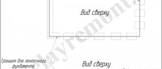
The first thing you need to do, and what the final result of your work will depend on, is to correctly mark the future house; trenches must be dug under all load-bearing walls, which will bear the maximum load. The width of the trench should be greater than the thickness of the planned walls to reduce the load.
Pegs should be driven into the corners of the future structure and along the load-bearing walls and a plan should be outlined. At the next stage, install a blind area with a retreat of several tens of centimeters from the pegs and wrap them around the perimeter with a rope, which will act as a ruler.
When is it advisable to install such a foundation?
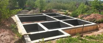
This type of foundation is a continuous strip of concrete mixture laid around the perimeter of the building. The construction of a strip structure requires lower financial and labor costs due to the rational use of reinforcement , concrete and other building materials.
Tape supports are best suited for heaving soils with a freezing depth of up to 1.5 m, because they are strong, durable (they last at least 100 years) and stable. The performance characteristics of such a foundation are sufficient to support the weight of small structures without basements.
When groundwater passes through the soil at a depth of 1.5 m or more, MZLF can also be used. At the same time, the cost of construction work increases due to measures to improve the drainage capacity of the soil.
Soil heaving
A characteristic feature of heaving soils is their susceptibility to frost heaving.
The process of soil heaving is the result of the freezing of moisture in it, which turns into ice.
The force of heaving in clay soils can destroy any structure, so construction on such soils requires a special technology for the work.
Since ice is less dense than water, its volume is greater. Heaving soils include three types of clay soils: sandy loam, loam and clay. Clay contains a lot of pores, which allows it to retain moisture. Accordingly, the more clay and water contained in the soil, the higher its heaving.
The degree of frost heaving is understood as a value indicating the susceptibility of the soil to possible heaving. The degree of heaving is determined as the ratio of the absolute change in soil volume as a result of freezing to the height of the soil before freezing occurred.
Thus, here it is possible to determine how the freezing process of the soil affects its volume. If the index of the degree of soil heaving is more than 0.01, then such soils are called heaving, that is, increasing by 1 cm or more when the soil freezes to a depth of 1 m.
Dependence of foundation characteristics on the type of soil conditions and number of storeys of structures
The calculation of a shallow basement is based on the weight of the house and the resistance of the soil, which depends on its composition and the degree of heaving.
The designers' task is to ensure the bearing capacity of the soil under the load of the structure through the concrete foundation. These dependencies have been studied by leading engineers, and the recommended values of the main characteristics are presented in the SNiP tables.
The table below displays changes in the technological characteristics of the foundation depending on the degree of soil freezing and the number of storeys of brick or block houses with reinforced concrete floors.
| Heaving degree | Soil composition | Number of storeys | Pillow width/thickness | Protrusion of concrete above the ground, cm | Reinforcement option |
| average | clay and sand | 1 | 0,6/0,3 | 20-30 | sinuses are filled with sand |
| clay | 2 | 0,6/0,3 | reinforced concrete monolith | ||
| sand | 0,6/0,5 | ||||
| clay | 3 | 0,8/0,4 | sinuses are filled with sand | ||
| sand | 1,0/0,8 | ||||
| strong | clay and sand | 1 | 0,6/0,5 | blind area | |
| clay | 2 | 1,0/0,4 | reinforced box | ||
| sand | 0,8/0,6 | ||||
| clay | 3 | 1,4/0,5 | 0 | ||
| sand | 1,2/0,6 |
Heat-protected shallow insulated foundation
Worthy of attention, especially in areas with severe winters, are heat-protected shallow foundations that use both principles of compensation for frost heaving of the soil.
- increased rigidity and insulation of the foundation.
Thermal insulation of such a foundation is carried out in a lightweight version
, which allows only to reduce the depth of freezing under the base of the foundation, and, consequently, the heaving force acting on the foundation.
Calculations and practice show that installing only a vertical layer of thermal insulation
to the entire height of the foundation and plinth, from the base of the foundation to the outer walls of the house, can
significantly reduce the depth of
soil freezing under the base of the foundation.
This combination allows, on the one hand, to reduce the size of the thermal insulation skirt of the foundation, and on the other, to facilitate the construction of a foundation with increased rigidity,
compared to the original version without thermal insulation.
Stages and features of construction
The construction of the MZLF begins with design, as well as site preparation (removal of construction debris and leveling of the surface).
Construction stages:
marking the area using pegs and ropes;- digging a pit up to 1 m deep;
- laying waterproofing materials (for example, roofing felt or film);
- filling with sand and compacting the layer up to 30 cm;
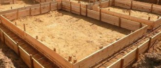
- construction of wooden formwork, reinforcement frame;
- pouring a concrete mixture (for baths choose concrete grades not lower than M200, for houses - not lower than M300);
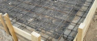
- laying the upper reinforced mesh on the still wet mixture;
- laying a heat-insulating layer (for example, extruded polystyrene foam) on hardened concrete;
- filling the insulation with sand and compacting it;
- If it is necessary to drain water, install a blind area.
The construction of the MZLF is carried out in the warm season. If construction is forced to stop for a period of cold weather, then conservation is carried out.
How to do it yourself?
To build a shallow reinforced strip foundation, you will need to perform the following steps:
- calculate the width of the foundation, the cross-section of the reinforcement;
- make a reinforcement drawing;
- clear away debris and plan the area;
- dig trenches;
- lay a drainage layer;
- arrange a footing or lay roofing felt;
- install formwork;
- lay and fasten the reinforcement;
- insert sections of pipes for communications and ventilation;
- perform concreting of the tape;
- provide care for concrete during its setting;
- remove the formwork from the tape;
- waterproof the foundation.
Then all that remains is to make a blind area and line the foundation with waterproof material. Each stage of construction of the MZLF has its own nuances.
Necessary calculations
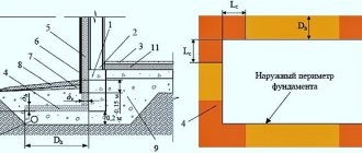
When calculating the foundation, it is taken into account that its laying depth is equal to the freezing depth, minus 25%.
Failure to comply with this requirement results in heaving of the soil and there is a risk of compromising the integrity of the structure.
The height of the base should not exceed the size of the underground part of the base.
To calculate the width of the structure, it is necessary to calculate the ratio of the weight load (t/m) to the calculated soil resistance (t/m2), (based on tabular data SNiP 2.02.01-83). The thickness of the sand-crushed stone platform is determined according to SNiP data.
Preparatory work and marking
The fertile layer is removed and the construction site is graded. At the intersections of the foundation and in the corners, stakes are driven in and a rope is pulled.
Digging a trench and arranging a cushion
The trench is dug to the required depth. Level the walls and corners if heavy equipment was used.
There is no need to plan the bottom of the trench to fanaticism. Pour a layer of clean coarse sand, without plant debris and clay. They tamp down, spilling water. Fine crushed stone is poured in and compacted as well.
A top leveling layer 50 mm thick is installed. The platform is covered with geotextiles, a footing is poured or roofing felt, folded in half and coated with bitumen, is laid.
There is a detailed article about the types of pillows and the features of the device for strip bases here.
Formwork assembly
The formwork is assembled from edged boards 25-40 mm thick. The shields should rise slightly above the tape. Be sure to inspect the cracks.
Builders practice covering formwork with plastic film. The formwork is fixed in place using external stops and internal spacers are installed.
Full information about formwork installation is here.
Reinforcement
The tape is reinforced with a reinforcement cage. Workers are considered to be horizontal rods that accept external loads. Vertical ones play a supporting role. The frame is knitted by twisting it with steel wire. The rods will have mobility and compensate for the resulting loads (when pouring concrete mortar or an earthquake). Welding will not withstand such loads.
All details of reinforcement of strip bases are here.
Pouring concrete
The concreting process is carried out without interruptions, not exceeding a pause of more than a day. Otherwise, a monolith will not work.
It is advisable to order delivery of the solution or organize its continuous production on site at the required pace.
The pouring process begins from the internal areas with a smooth transition to the external perimeter. You cannot pour concrete at one point and wait for it to spread over the tape. Fill the formwork at once from different points, evenly distributing it along the length.
Next, the surface is covered with polyethylene from hot sunlight. For the first 3 days, the tape is moistened after 4 hours, then another week after 8 hours to extend the setting time of the concrete. This ensures the strength of the monolith. After 10 days, the formwork is removed. After a month, construction can continue.
Formwork removal and waterproofing
Removing the formwork does not mean the end of the construction of the MZLF. It is necessary to perform horizontal waterproofing using two layers of rolled roofing material and coat the side surfaces of the foundation with bitumen.
You can use any impregnating and coating materials that prevent moisture penetration. Reliable waterproofing will protect your home from destruction and mold development.
The sinuses on the outer and inner sides of the foundation are filled with sand and a blind area is created that will protect the foundation from rain and melt water. If everything is done correctly, the water will flow along the concrete strip towards the drainage well.
Insulation of the base and blind area
To insulate the base and blind area, penoplex, penofol, liquid polyurethane foam, etc. are used. Any insulation with moisture-proof properties will be suitable, depending on the developer’s budget. The tape is insulated from the inside over the entire surface, except the horizontal one.
Anti-heaving measures
Key stages of construction of the MZLF are carried out taking into account the need to protect the foundation of the future building from heaving.
In accordance with this, the following measures are being taken:
- Medium and coarse sand is used as a material for cushioning and filling the sinuses on the sides of the structure, because it allows water to pass through well.
- A layer of geotextile under the cushion prevents siltation.
- A drainage pipe, laid 20 cm below the base and at a distance of more than 1 m from the foundation, serves to drain excess groundwater.
- The foam layer in the foundation serves to insulate heat and moisture.
- The blind area performs a waterproofing function and reduces soil freezing in the immediate vicinity of the building.
- Storm drains in the local area drain excess water.
Alternative options
In addition to MZLF, when designing construction on heaving soils, other types of foundation can be considered:
slab foundation - effective for large-scale structures with walls made of brick or heavy wood;- pile type - installed in wetlands at a level below the freezing depth;
- columnar frame - suitable only for light outbuildings, since it is laid shallow.
The choice of foundation type depends on the structural features of the structure, material capabilities and equipment of the developer.
Calculation of the flexibility index of building structures
1. Indicator of flexibility of building structures l
determined by the formula
,(1)
where EJ
— reduced bending rigidity of the cross-section of building structures in the foundation-basement-reinforcement belt-wall system, tf.m2, determined by formula (4);
WITH
— coefficient of foundation rigidity during soil heaving for the bases of strip foundations;
L
— length of the wall of the building (compartment), m;
,(2)
for columnar foundation bases
,(3)
Here pr
,
hfi
,
b 1
- the same notations as in paragraphs. - ;
A
f is the area of the base of the columnar foundation, m2;
ni
- the number of columnar foundations within the length of the wall of the building (compartment).
2. The reduced bending rigidity of the cross-section of building structures in the foundation-basement-reinforcement belt-wall system, tf/m2, is determined by the formula
[EJ
] = [
EJ
]f + [
EJ
]z + [
EJ
]p + [
EJ
]
s
,(4)
where EJ f
,
EJ z
,
EJ p
,
EJ s
- respectively, the bending rigidity of the foundation, plinth, reinforcement belt, building wall.
3. Bending rigidity, tf/m2, of the foundation, plinth and reinforcement belt is determined by the formulas
f
=
g f Ef
(
Jf
+
Ayc2
);(5)
z
=
g z Ez
(
Jz
+
Azyz2
);(6)
p
=
g p Ep
(
Jp
+
Apyp2
);(7)
where Ef
,
Ez
,
Ep
- respectively, the deformation modules tf/m2, the foundation material, the base and the belt;
Jf
,
Jz
,
Jp
- respectively, the moments of inertia, m4, of the cross-section of the foundation, plinth and reinforcement belt relative to its own main central axis;
A
,
Az
,
Ap
- cross-sectional area, m2, of the foundation, plinth and reinforcement belt;
y ,
yz , yp
- respectively, the distances, m, from the main central axis of the cross-section of the foundation, plinth and reinforcement belt to the conditional central axis of the cross-section of the entire system;
g f ,
g z , g p
are respectively the coefficients of the operating conditions of the foundation, plinth and reinforcement belt, taken equal to 0.25.
The bending rigidity of a foundation consisting of blocks not connected to each other is assumed to be zero. If the base is a continuation of the foundation or their joint work is ensured, the base and foundation should be considered as a single structural element. In the absence of reinforcement belts EJ p
= 0. If there are several reinforcement belts, the bending rigidity of each of them is determined by formula (7).
4. Bending rigidity, tf/m2, of walls made of bricks, blocks, monolithic concrete (reinforced concrete) is determined by the formula
s =
g s Es(Js + Asys2),
(8)
where Es
— deformation modulus of the wall material, tf/m2;
g s
- coefficient of wall operating conditions, taken equal to: 0.15 - for walls made of bricks, 0.2 - for walls made of blocks, 0.25 - for walls made of monolithic concrete;
Js
— moment of inertia of the cross section of the wall, m4, is determined by formula (9);
A s
— cross-sectional area of the wall, m2;
y s
— distance, m, from the main central axis of the cross-section of the wall to the conditional neutral axis of the cross-section of the entire system.
The moment of inertia of the cross section of the wall is determined by the formula
,(9)
where J 1
and
J 2
- respectively, the moment of inertia of the wall section along the openings and along the piers, m4.
The cross-sectional area of the wall is determined by the formula
,(10)
where bs
— wall thickness, m.
The distance from the center of gravity of the reduced cross-section of the wall to its lower edge is determined by the formula
,(11)
5. The state from the main central axis of the cross section of the foundation to the conditional neutral axis of the foundation-basement-reinforcement belt system - wall is determined by the formula
,(12)
where Ei
,
Ai
are, respectively, the deformation modulus and cross-sectional area
of the i
-th structural element (basement, wall, belt);
ji
— coefficient of operating conditions
the i
-th structural element;
yi
— the distance from the main central axis of the cross-section of
the i
-th structural element to the main central axis of the cross-section of the foundation.
6. Bending rigidity, tf.m2, of panel walls is determined by the formula
,(13)
where Ej
,
Aj
are, respectively, the deformation modulus, tf/m2, and the cross-sectional area, m2, of
the j
-th bond;
m
— number of connections between panels;
di
— distance from
the j
-th connection to the main central axis of the cross-section of the foundation, m;
y
- the distance from the main central axis of the cross section of the foundation to the conditional neutral axis of the foundation-wall system of the building, determined by the formula
,(14)
in which n
— the number of structural elements in the foundation-wall system.