31.03.2021
Sewerage
Editorial staff of the “New Place” website
Share
From this article you will learn
:
- Tasks and types of sewer wells
- Materials for the manufacture of sewer wells
- Calculation of sewerage and well installation depth
- Subtleties of installation of different sewer wells
The construction of a sewer well cannot be called complicated. It plays an important role in the functioning of a central or autonomous drainage system. There are several types of these wells depending on the purpose and design features.
The purpose of the wells is to collect wastewater, distribute the main line junction among the discharge zones, and clean certain sections of the pipeline. We will tell you further about which sewer well device meets all these requirements and what is needed for installation.
Types of drainage wells
According to its purpose, the drainage shaft can be:
- Lookout.
- Collector.
- Absorbent.
The inspection well for drainage has several other working names. It may be called audit or inspection. Designed to monitor the technical condition of the drainage system, its timely cleaning, maintenance and repair.
An inspection well is installed for drainage in places where pipes turn or change their direction. On straight pipes, installation of shafts is carried out every 30 meters with a pipeline diameter of 15 cm or every 50 meters with a pipeline diameter of 20 cm. Additionally, you can install an inspection well for drainage at the intersection points of the drains.
If it is planned that there will be a descent for maintenance, then the plastic inspection well shaft must have a diameter of at least 1.0 meters. If the shaft is cleaned with water pressure from an external hose, then the optimal diameter for the shaft will be 35-45 cm.
Plastic stormwater collection wells are typical for private country houses. If the site has a slope, then the installation of the shaft is carried out at the lowest point of the site.
If the site is flat, then the installation of drainage pipes is carried out at a slight slope of the sewer system, and storm wells are installed slightly below the level of the pipes. This will ensure a random outflow of water from the pipes into the mine.
The liquid can accumulate or drain naturally into the central drainage channel, the nearest body of water. If there is no outlet, then the water is pumped out using a pump, which often comes with the tank.
The collector storage tank can serve as an element of the sewer system. The drainage well for sewage is equipped with a system for removing solid elements. After passing through several levels of purification through the septic tank, liquid accumulates in the shaft, which is subsequently pumped out. The dimensions of the drive are not adjustable, it all depends on the wishes of the owner.
An absorption or filter tank is designed to drain a certain small area of the area where it is impossible or there is no need to install a general drainage structure. For drainage, soil is selected in which the volume of liquid passing through the well is no more than 1 cubic meter. m.
A characteristic difference between a well is the absence of a bottom, its shape and method of installation. It has the shape of a truncated cone, which is installed with a smaller diameter upwards. If desired, you can install a shaft of a different shape.
For installation, a pit with a depth of about 2.0 meters will be equipped. A cushion of crushed stone, 2-3 cm thick, is placed at the bottom of the pit. But the cushion is installed in a cone wrapped in geotextile. Inside the shaft, a lining is made of small stone, crushed stone or slag, which is covered with geotextile. When the mine is flooded, the liquid is pumped out and the geotextiles are replaced.
By type, wells are divided into:
- Turning.
- Tee.
- Cross.
- Passage.
- Dead end.
- No holes.
A rotary plastic drainage well is installed at the places where the pipes turn. Often these are the external and internal corners of buildings. These areas are most vulnerable to clogging. The pipes at the rotary well are located at an angle of 90°.
A cross-well and a tee-well can be located in the place of rotary shafts, to which additional drainage lines are connected. The cross and tee can be used as inspection points in certain areas where several drainage lines are connected to one point.
The pipes in such shafts are located at an angle of 90° relative to each other. The dead-end type of shaft is applicable to a collector well and has one inlet pipe. A storage tank without holes is used as an absorption shaft.
Captages of springs
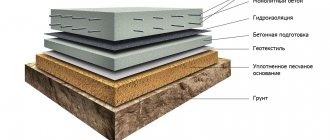
Groundwater is divided into pressure (artesian) and non-pressure. They can emerge on the daytime surface. In this case, they are called springs. The outlet of free-flow water is called a descending spring, and the outlet of pressure water is called an ascending spring. Spring water has an excellent taste, high quality and can be used for drinking purposes without purification.
To collect such water, springs are captured using capture chambers. To capture water from rising springs, chambers are installed to receive water through the lower part of the chamber. To increase the water intake surface, capture is carried out in the form of horizontal water intakes made from reinforced concrete, concrete or ceramic pipes with round or slotted holes. To prevent soil particles from being washed out by water into water intakes, they are sprinkled with filtering sand and gravel media.
To prevent the entry of polluted surface runoff into water intakes, a clay cushion is placed on the surface of the earth under the water intakes. The simplest horizontal water intake can be made from short pipes with gaps at the joints, from brick or rubble stone without the use of mortar. To inspect and clean horizontal water intakes, inspection wells are installed every 50–150 m along their length.
Water is taken from the ascending spring (see Fig. 5) through the bottom of the capture chamber, and from the descending spring (see Fig. 6) through the holes in the chamber walls.
Rice. 5. Device for capturing an ascending spring
Design and installation features
You can install a plastic drainage well on your site without specialists. For installation, you will need 1-2 assistants, mainly to lower the container to the bottom. But before this it is necessary to carry out preparatory work.
With a monolithic product everything is simpler; it is almost ready for installation. Disassembled finished products must be assembled according to the instructions. And if you decide to make a tank from a large-diameter pipe, then first you need to cut it to the required length.
In finished products, holes for pipes often already exist, but in home-made products, they are pre-cut in accordance with the diameter of the drains. Rubber seals and plastic couplings are inserted into the holes. All seals are lubricated with sealant to prevent leaks.
After this, they begin to dig and prepare the pit, taking into account several parameters:
- The depth should be such that the points where the pipes enter are below the freezing point of the soil, and the bottom of the container is at least half a meter above the groundwater level.
- You also need to take into account that at the bottom of the pit there will be a cushion of crushed stone 15-20 cm high.
- The width of the pit is 40-60 cm greater than the diameter of the container.
- The hatch will then have to rise 10-15 cm above the ground.
If the area is characterized by a seasonal rise in groundwater, then an additional cement base must be poured onto the bottom.
After the cement has hardened, you can install:
- The reservoir is released to the bottom.
- Use a level to check whether the container is level.
- Connect the pipes for the drainage well to the nozzles. Be sure to treat all connections with sealant.
- The tank is backfilled with a sand-gravel mixture. This is done in layers, each layer being thoroughly compacted.
- Install the plastic cover (hatch).
This completes the installation. If necessary, a drain pump is released into the collector.
Installation video of the Wavin Tegra 1000 well:
SNiP standards
The construction of any sewer well is regulated by special sanitary and technical standards, reflected in a special document known as SNiP.
This document requires some preliminary work.
Necessary:
- determine the location of the well and mark the area;
- uproot all trees and bushes that interfere with construction;
- equip the construction site - ensure free access for equipment;
- draw up a plan (scheme) and coordinate it with neighbors and the city water utility.
Construction work also has strict regulations and includes:
- preparation of the pit (pit);
- filling the bottom with crushed stone and sand;
- carrying out complete waterproofing of the bottom using concrete mortar;
- installation of concrete rings or plastic tank;
- laying pipes;
- sealing all pipes with cement mortar or bitumen (for concrete structures, holes around the supplied pipes are sealed);
- functionality check (testing for the possibility of leakage);
- backfilling the well from the outside (fine crushed stone and soil are used for plastic, clay for concrete);
- additional treatment of concrete structures with waterproofing materials.
Basic technical requirements.
Septic tanks, as a rule, are a set of settling chambers that look like sealed wells with a rectangular or circular cross-section. The sewer well is constructed in such a way that it ensures water purification by fermentation. At the same time, untreated wastewater should in no way enter the ground. To do this, the bottom and seams and wells are concreted very carefully. They also use external coating of the septic tank with hot bitumen, and the bottom of the pit is compacted with clay.
Types and features of wells
There are two types of water intake wells:
- tubular;
- mine
The first type is popularly called a column. Usually they were installed on the streets of villages. A hand pump is used to extract water from deep in such wells. These wells are installed in areas of shallow aquifers. Its installation is very fast. But to build a tube well, you will need drilling equipment, because the hole is not dug, but drilled.
A shaft well is the most affordable option for self-installation. They dig it with a shovel, and strengthen the walls. This is a traditional well for country houses and cottages. Depending on the material of manufacture, there are several types of mine water wells:
- plastic;
- reinforced concrete;
- brick or stone;
- wood.
Reinforced concrete wells are the most popular. They are durable (can last up to 50 years). Their depth reaches 15-20 m. However, installing such a water intake device will require a lot of labor. First of all, it will take a lot of effort to dig a deep hole. At the same time, its diameter must be larger than the size of the rings in order to fill the outside with sand and gravel. And to lower the concrete rings you will have to order a construction crane. At the bottom of such a well, a filter is installed from a sand and gravel cushion with a height of 300-400 mm.
Recently, more and more often, owners of private houses are choosing plastic water wells. Their main advantage is that it is a one-piece design due to the high tightness of all joints and seams. The dimensions of such structures can be any depending on the requirements. They are no less durable than reinforced concrete devices and can also last up to 50 years. Their additional advantage is the speed of installation without the use of construction equipment.
Wooden and brick water intake structures are a thing of the past. Nowadays they are practically not made due to the labor intensity and duration of the construction process. In addition, these structures do not meet the requirements of SNiP, because silt and dirt quickly settle on the brick and wooden walls of such water wells, which reduces the quality of drinking water.
Depth of sewerage installation and SNiP requirements
Borehole water supply for a suburban area
Shafts with a depth of more than 20 m are called pipe (tubular) or artesian. If underground aquifers lie very deep, it is necessary to drill wells up to 200 m, but most often this happens for industrial purposes. The quality of the liquid in artesian springs is much higher than that of a well: it practically does not contain nitrates, salts of harmful metals, or pathogenic bacteria that enter wells from the perched water. The only disadvantage of well equipment is the high cost.
Shallow well (for sand)
Sand wells are the most acceptable way to provide a country house with the best quality water. Their depth ranges from 15 m to 35 m (less often 45 m), and the water consumption is on average 0.8-2.2 m³/h. Drilling must be carried out by specialists, since it is necessary to detect underground horizons of aquifer sand and correctly install the filter. The drilling process lasts 2-3 days, then it is necessary to line the shaft with pipes made of steel or propylene. The lower part of the equipment is equipped with a sand filter or a more powerful filter column.
Sand well construction diagram
The productivity of the structure is enough to provide water to a family of 3-4 people. The quality of the liquid is not as ideal as that of an artesian, but much higher than that of a well, since the ingress of surface water is excluded. If you install a centrifugal pump and automatic equipment, the sand well will function uninterruptedly throughout the year. Drilling is possible using a compact drilling rig; a license and a package of permits are not required.
deep well
The depth of an artesian well is from 30 m or more, in suburban areas the maximum does not exceed 200 m. A package of permits is required for its installation. Drilling must be done by specialists, as you will need heavy construction equipment (ZIL, KamAZ) and a powerful rotary unit. The drilling process involves breaking up hard rock, removing it from the mine, and installing casing pipes. The maximum number of casing pipes for one structure is 3 pieces; such a prefabricated structure is called telescopic. Welding has recently been used extremely rarely; the main method of connecting elements is threaded. The lower water layers are isolated from the upper ones using a special material - compactonite, granulated dry clay.
Artesian well with double casing
After installing the pipes, experimental flushing is required until clean water is obtained. Samples are taken for analysis to give permission to use water as drinking water. The owner is issued a passport, which indicates the technical data of the structure and terms of use.
Classification of wells for sewerage
Structures related, according to technical terminology, to sewer wells are divided into several types.
The division is made depending on what classifying features we will use. For example, you can divide wells by material of manufacture, by purpose or by the method of their construction.
The following classification characteristics and the corresponding types of modern sewer wells are distinguished. The first is produced by the medium, which is transported by the sewer system.
The drainage networks on which sewer wells are installed are designed to move wastewater of different composition and degree of aggressiveness, these are:
- Household. These include waters that have changed their composition as a result of mixing with waste and garbage. Depending on the contaminants they contain, they are divided into household and fecal.
- Industrial. These include waters that have changed their mechanical and chemical composition as a result of contamination with industrial waste.
- Atmospheric. These include water formed as a result of the active melting of winter precipitation, flood and rain water.
In addition to the listed types of wastewater, the sewerage system receives flows collected by the drainage system, the task of which is to drain the territory or drain groundwater from underground building structures.
Wells of sewer systems are divided according to the material of manufacture into:
- Brick. Brick was once a commonly used material for making wells, but over time there are fewer and fewer brick structures.
- Concrete. Concrete structures are today the traditional material option for a sewer well.
- Plastic. It is obvious that compositions with a polymer base are the material of the future; it will one day replace both brick and concrete.
Plastic or composite ready-made well structures are attractive because they are lightweight and easy to install. They are pleased with their resistance to chemical influences during prolonged contact with aggressive environments. They tolerate sharp and smooth temperature fluctuations well and do not allow or absorb water at all.
Sewage systems are divided into floating and export. The former move wastewater to treatment plants, facilities or discharge fields. The latter only collect wastewater for subsequent pumping and removal. The wells included in both types of systems perform both identical and different functions.
According to their functional responsibilities they are divided into:
- Cumulative. They are used to accumulate wastewater for subsequent extraction and removal. Naturally, they are constructed in sewerage systems.
- Collector. Designed to collect wastewater from several sewer branches and to direct it to a storage tank, treatment plant or discharge fields. They are installed in both floating and export branched networks.
- Filtering. They are used to dispose of the liquid fraction of wastewater naturally. They play the role of compact treatment facilities that transport pollutant-free media into the ground or into water bodies. They accompany exclusively the floatable type of sewerage.
- Observations. They are constructed on collector sections longer than 50 m, as well as at all turning points and junction points of highways. Necessary for monitoring the operation of the sewer system, for periodic cleaning and repair activities. They are installed in both types of sewers.
- Drops. They are located in areas with sharp changes in altitude. The reasons for the construction include ensuring buried discharge into the reservoir and the need to slow down flows on sections of the pipeline with a large slope. They may be present in both exhaust and floating sewers.
The classification of manholes is much more complex. We'll talk about this a little below, but now we'll look at different types of wells in more detail.
The importance of reinforced concrete sewer wells in the system of disposal of domestic wastewater
The design of any modern house involves dividing the sewer system into several parts:
- Sewer lines laid throughout the house - it fits the outlets of sinks, toilets and bathtubs, as well as other plumbing fixtures;
- A sewer pipe running in the direction from the house to the storage tank;
- Actually, the storage sewerage facility itself.
It is important to note that in addition to the storage well, there are other types of standard sewer facilities. The most popular of them are:
- Inspection rooms - their purpose is to monitor the current condition of the sewerage system and, if necessary, carry out cleaning.
- Drop - applicable in systems where a significant difference in height is provided structurally.
- Rotary – needed when the design of the system involves sharp turns. In addition, they are used as viewing rooms.
The fundamental difference between the varieties mentioned above and the storage well is that they are used so that efficient transport of wastewater can be ensured. The purpose of the storage well is, accordingly, reduced to the accumulation of wastewater intended for subsequent pumping.
Accessories for a concrete well
Today, manufacturers produce concrete rings of different sizes, so choosing the ones that suit you is not difficult. The wells themselves are constructed from the same set of components, which include:
- bottom – reinforced concrete slab;
- rings;
- neck;
- cover with hatch;
- plate for a partition inside the ring - used to create multi-stage cleaning.
Dimensions of concrete rings
The size of the purchased rings depends on the type of well for which they will be used. The table below shows the main standard sizes used for the construction of sewer wells:
| Marking | Size(mm) | Weight, kg) | ||
| Inner diameter | Wall thickness | Height | ||
| KS-7-1 | 700 | 80 | 100 | 46 |
| KS-7-1.5 | 700 | 80 | 150 | 68 |
| KS-7-3 | 700 | 80 | 350 | 140 |
| KS-7-5 | 700 | 80 | 500 | 230 |
| KS-7-6 | 700 | 100 | 600 | 250 |
| KS-7-9 | 700 | 80 | 900 | 410 |
| KS-7-10 | 700 | 80 | 1000 | 457 |
| KS-10-5 | 1000 | 80 | 500 | 320 |
| KS-10-6 | 1000 | 80 | 600 | 340 |
| KS-10-9 | 1000 | 80 | 900 | 640 |
| KS-12-10 | 1200 | 80 | 1000 | 1050 |
| KS-15-6 | 1500 | 90 | 600 | 900 |
| KS-15-9 | 1500 | 90 | 900 | 1350 |
| KS-20-6 | 2000 | 100 | 600 | 1550 |
| KS-20-9 | 2000 | 100 | 900 | 2300 |
When purchasing, pay attention to the labeling; it contains all the necessary data, for example KS-20-9:
- KS – wall ring;
- 20 – diameter;
- 9 - height.
The diameter and height in the markings are indicated in decimeters.
Road crossings
Sewer aerator
In cases where a passage under a public road is required, sewer wells are installed on both sides of the roadway. Their design must ensure the laying of pipes passing under the road in steel or concrete cases. This solution will ensure the safety of structural elements from the effects of vibrations caused by traffic.
Construction of road crossings
Installation of inspection wells
All structures, regardless of their type and purpose, have a similar structure. The main details are:
- tray;
- bottom;
- Luke;
- neck;
- shaft or chamber.
Most often, wells are a round shaft made of various materials. Cameras are installed if:
- the inlet and outlet pipelines differ in diameter;
- the pipeline slope changes;
- the flow of water changes direction;
- several pipes are connected into one.
Straight sections are also equipped with chambers rather than shafts. Tray - used to connect pipes, usually made of concrete, the height is equal to the diameter of the pipe. The bottom is filled with concrete, and the neck, as well as the shaft, can be varied. The material for the shaft is concrete rings or polymer materials with high ring strength, such as Korsis pipes.
Video: Plastic sewer wells
Nuances of waterproofing work
Inspection wells are dry-type technological structures, which are most often located in wet soils.
When installing these structures, waterproofing is a mandatory measure to guarantee the safety of the pipeline fittings and the effective work of cleaning or flushing the pipes.
Practice shows that leaks in prefabricated concrete structures most often occur not due to defective products, but due to improper processing of joints. This means that sealing seams is a serious and responsible procedure.
Three types of insulation are used as waterproofing compounds:
- bitumen-polymer;
- cement-polymer;
- polymer.
Bitumen-polymer waterproofing includes coating materials (mastics) and weld-on rolls, the gluing of which requires heating to a certain temperature. The second option is used less frequently, since special skills in using a gas burner are required.
One of the solutions for sealing seams using domestic waterproofing materials Penetron and Penekrit. The first is penetrating polymer-type insulation, the second is suture material, which is sold in the form of a dry mixture.
Cement-polymer compositions are cheaper, have excellent technical characteristics and are suitable for independent use. The prepared mixture is applied with a spatula in 2-3 layers to a moistened, cleaned surface, leveled and allowed to dry.
Polymer waterproofing is elastic and durable. Mastics and rolled membranes are ideal for potentially moving structures - even with a slight displacement, the sealing of the joints will be maintained.
In addition to the walls, it is also necessary to insulate the base of the well. It is usually done at the stage of laying the concrete slab, before installing the rings. The slab is covered with a cement-polymer composition, and the lower joints are also covered with it.
Stone wells
Insulating pipes in a well with bitumen After this, the following work is performed for a concrete or reinforced concrete well:
- Preparing the base. Laying a slab or installing a concrete pad 100 mm thick from M-50 concrete
- Construction of a tray of the desired shape made of M-100 concrete with steel mesh reinforcement
- Sealing pipe ends with concrete and bitumen
- Insulation of the inner surface of concrete rings with bitumen
- Rings of sewer wells are installed (carried out after the concrete tray has gained strength, 2-3 days after installation) and a floor slab with M-50 mortar
- Grouting the joints between the prefabricated parts of the well with cement mortar
- Waterproofing joints with bitumen
- Finishing the tray with cement plaster, followed by ironing
- Installation of a clay castle at the entry points of the pipes with a width of 300 mm and a height of 600 mm larger than the outer diameter of the pipes
- Well testing (carried out within 24 hours by filling it with water to the top edge, installing temporary plugs on the pipes). Considered successful if no visible leaks are detected.
- External backfilling of well walls followed by compaction
- Construction of a 1.5 m wide concrete blind area around the well neck
- Insulation of all remaining joints with hot bitumen
The installation of brick sewer wells is carried out in a similar way, but here, instead of installing prefabricated elements, masonry is used.
Waterproofing is done in exactly the same way.
Thus, the installation of wells made of stone materials is carried out for all types of sewerage: domestic, storm or drainage.
However, in the case of a stormwater well, lattice hatches can be installed on the well, which simultaneously serve as a catchment area.
For drainage, the well itself can be a drainage element through special holes in the walls, but this design requires special calculations.
At the same time, there are slight differences in the components that the series defines: sewer wells KFK and KDK - for domestic wastewater, KLV and KLK - for storm water, KDV and KDN - for drainage.
The table of sewer wells by size is as follows:
Table of sewer wells
The process for drop wells looks a little more complicated due to their more complex configuration.
Drop well
Here, depending on the specific design, in addition to the tray design, in some cases it is necessary:
- Riser installation
- Water jet equipment
- Installation of a water barrier wall
- Creating a practice profile
- Pit device
The installation of the shaft body, base and ceiling itself is carried out according to the same rules.
The only exception concerns a drop well with a riser - a metal slab must be laid at its base to prevent the destruction of the concrete part of the structure.
It looks like this:
- Riser
- Water pillow
- Metal plate at the base of the pillow
- Receiving funnel riser
Design of a well with a riser The receiving funnel is designed to compensate for the vacuum that can be created in the riser due to the rapid movement of wastewater.
It is necessary to create differential sewer wells with your own hands using a practical profile only in exceptional cases - such a design is provided for pipelines with a diameter of 600 mm and a differential height of up to 3 m.
Similar pipe diameters are not used in individual drainage systems. But other types of wells can be successfully used in local sewerage.
In accordance with the requirements of SNiP, sewer drop-off wells are installed:
- If necessary, reduce the depth of the pipeline
- At intersections with other underground utilities
- To regulate the flow rate
- In the last flooded well before the wastewater is discharged into the reservoir
Typical cases when installing a drop well in a suburban area is advisable:
- Fast flow diagram If there is a large difference between the calculated depth of the yard sewerage system and the level of wastewater discharge into the septic tank or central collector (laying the pipeline at a shallower depth will significantly reduce the volume of excavation work)
- If there is a need to bypass other utility networks underground
- If there is any doubt as to whether the flow rate in the system corresponds to the volume of waste water. With a small volume, too high a speed can prevent self-cleaning (washing out sediment) of the pipe walls. Equally, if the speed is too low, sediment may form too intensively, then it makes sense to arrange a high-speed flow to accelerate it.
The meaning of this difference is that due to the creation of a large slope in a short section of the system, the drains begin to move much faster, without having time to cling to the inner walls of the pipe.
Water protection
The control well on the sewer must be impermeable to water to prevent contamination of the soil and the environment by runoff. For this purpose, water protection is carried out using special means. It can be:
- rolled materials (roofing felt, waterproofing, PVC film);
- cement mortars;
- mastics;
- coating mixtures;
- membrane materials.
Waterproofing is carried out as follows. First, prepare the surface, clean it, and level it. Then the joints and joints are filled, only then the entire inner surface is covered.
Sewerage service control points can be divided into two types:
- serviced;
- managed.
The first type of device has a hatch; it is opened for periodic inspection of the condition of the system. In controlled points, control occurs using a special control cabinet. There is no need to go inside when the measurement occurs automatically. Equipment inside the monitoring well measures environmental indicators and shuts off the water if the measurement results differ from the norm.
The sewer system includes control wells for monitoring communications, periodic inspection, cleaning and maintenance. Solving all problems related to testing the quality of wastewater and the functionality of the entire system is impossible without control points.
Self-installation of drainage wells
Let's look at how to make a drainage well with your own hands. Depending on the type of well, the methods of its manufacture also differ.
Installation of a plastic storage well
The material for making such a well can be corrugated plastic pipe of various sizes.
Important: Wells of this type must be installed below all drainage pipelines, ensuring unimpeded flow of water to them. 1. A pit is dug for the future tank
A pit is being dug for a future reservoir.
1. A pit is dug for the future tank.
2. The required length of the corrugated pipe is measured, after which it is cut.
3. A sand cushion is poured into the hole or a solid concrete base is created.
4. A prepared container is installed in the prepared pit, which has bends for connecting pipes. Holes for inlet pipes can be made after installing the container in a permanent place. Many ready-made wells already have special outlets, so connecting them to the drainage system is easy.
5. Using bitumen mastic, a plastic bottom is glued to the pipe.
6. Drainage pipes are inserted into the well and the cracks are sealed.
7. The gaps between the walls of the well and the pit are filled with crushed stone, sand or a mixture of sand and cement.
Tip: It is advisable to immediately place a drainage pump inside the well. through which water will be pumped out. You can also use a submersible pump, which will be lowered into the well manually, as needed, or a surface type pump.
8. The storage tank is covered with a lid on top to prevent its contamination, and at this point the installation of the drainage well can be considered completed.
The installation of an inspection-type drainage well with your own hands is carried out according to a similar scheme, except for installing a pump. There is also no need to place it at the lowest point of the site.
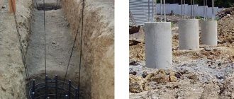
Installation of a well made of concrete rings
For the manufacture of concrete wells, it is better to use reinforced rings with a lock. If they are not available, then ordinary concrete products will do. The thicker they are, the longer they will last.
The work is performed using special loading equipment in the following sequence:
1. A pit of the required dimensions is prepared.
2. Sand or gravel is poured onto the bottom of the pit. If a filter container is being made, the thickness of the pad should be at least half a meter.
3. The first ring with the bottom is placed on the pillow. If rings without a bottom are used, then a concrete screed is made from below the first ring.
4. The next rings are laid on top of the previous ones. When installing concrete rings, the seams between them are sealed with concrete mortar or bitumen mastic.
5. When the last ring is installed, holes are made in it (if there are none already) for the entrance of drainage pipes.
6. Pipes are inserted into the holes of the ring, after which all joints are carefully sealed.
7. A cover is installed on top of the well. You can use plastic or metal lids, as concrete products are too heavy.
8. The voids between the walls of the pit and the concrete rings are filled with sand, gravel or crushed stone.
Setting up a drainage well is not a very difficult task. You can handle this kind of work yourself, especially when installing plastic products.
How to monitor the water quality of drinking wells
When the relevant authorities check the quality of water in drinking wells, the surrounding area is also subject to inspection. The main types of water quality control:
- Planned. It is carried out after a certain period of time. Includes a set of basic measures to determine the water quality of all water supply sources (wells, wells).
- Selective. Can be carried out in regions where problems with water supply systems were previously noticed.
- According to one-time applications. The initiator of such a check is the direct owner of the land plot. Performed to check the suitability of water.
Often, the first water intake may include too many harmful bacteria and microorganisms. Then a more in-depth examination of the water is carried out, which determines the cause of the deterioration of the water. All indicators are compared with the standards of the relevant instructions.
To improve the quality of water, the drinking well can be cleaned and subsequently disinfected. If after this the problem has not been eliminated, then the quality of the water is improved by using special preparations with a high chlorine content. If the pollution is of a chemical nature (especially pollution with aggressive substances), then a decision may be made to eliminate the source.
Installing an inspection hatch and laying pipes
In order to properly build a sewer shaft, you need to take into account the features of assembling parts at all stages of its construction. Not the last place in the installation process is the installation of the inspection hatch. Its device is quite simple, but requires precise execution of the necessary work:
- The last ring of the well is covered with a flat slab with a hole for an inspection hatch;
- A metal rim is mounted along the edge of the hole. It will protect the stove from mechanical damage when opening the lid;
- Then carefully install a metal hatch, preferably cast iron.
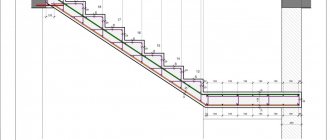
When the construction of the well is completed, you should immediately begin laying sewer pipes. According to SNiP standards, during their installation the following parameters must be taken into account:
- The laying depth of sewer pipes must be at least 70 cm;
- In order for sewage to flow through the main by gravity, the slope of the pipes must be at least 2 cm per 1 linear line. meter of sewer line;
- The entry of the pipeline into the sewer shaft must be located above the level of the sewage disposal pipe.