- home
- Low-rise construction
- Floor slabs
Reading time: 10 minutes
4359
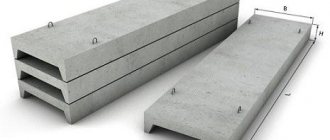
Ribbed floor slabs are structural elements made of reinforced concrete, which are actively used in modern low- and high-rise construction. The slabs are distinguished by excellent characteristics of strength, reliability, load-bearing capacity, evenly distribute serious loads, and guarantee the safe operation of buildings even under conditions of increased seismic activity.
Ribbed floors have a solid base, as well as ribbed elements on the sides, due to which they are able to withstand considerable bending loads. For use under conditions of increased loads, the slabs are reinforced with transverse ribs. Where the loads are minimal, concrete is removed, adding it in compression zones.
Thanks to this, the prefabricated ribbed slab has maximum strength, the ability to withstand maximum loads with a noticeable reduction in material (saving and reducing the weight of the structure).
The pitch of the floor slab with beams should not be more than 6 meters. The ribbed slab can act as part of the roof or basement. Most often, such elements are used in industrial construction, but rarely in residential construction, since the ribs create an uneven surface that is difficult to finish.
Ribbed floor slabs are made from heavy/light, dense silicate concrete. Different steel reinforcement is used (indicated by letters/numbers). Modern manufacturers create products in accordance with GOST 28043-89.
Main types of ribbed slabs:
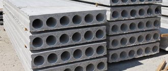
- PG – without cavities
- PV – with holes for ventilation
- PF – with lights
- PL – used to remove roofing
When choosing a slab, you must take into account all types of expected loads on the structure, look at the dimensions and technical characteristics of the product.
- 1 Materials used
- 2 Scope of use
- 3 Design features
- 4 Options
- 5 Types and designation of floor elements with a height of 30 cm
- 6 Classification and labeling of products with a height of 40 cm
- 7 Recommendations for load calculations
Materials used
Ribbed floor slabs are produced in accordance with established norms and standards. The main characteristic of the slab is the unit of load accounting, which is calculated in kilograms per square meter.
Basic requirements for the quality of slabs:
- Exact compliance of sizes with the values established in GOST
- Strict compliance with the parameters and characteristics specified, which is verified during inspections and confirmed by certificates
- Good resistance of slabs to moisture, temperature changes, deformation, cracking
The materials from which the monolithic ribbed floor is produced must also be of high quality and meet the requirements. Concrete must have a density of 1810-1990 kilograms per square meter. The porosity approved in GOST must be checked. The density of heavy concrete can reach 2550 kilograms.
The tension of the reinforcement in the slab is measured after the concrete has set. Heavy concrete corresponds to grades M455 or M650, light concrete - grades M250 or M300.
The fittings must be made from steel grades specified in GOST. All reinforcement cages must strictly comply with standards. Only tension indicators can change, and then by a maximum of 10%.
In the production of ribbed slabs, reinforcement from approved steels of the required diameter, with certain dimensions and shape of loops, and tension by electromechanical/mechanical methods are used. All metal elements must be treated with anti-corrosion compounds.
Subject to compliance with all standards, the slabs are rigid and durable, capable of withstanding heavy loads for a long time.
Why is it important to get the math right?
The safety margin per 1 m2 allows both during construction and reconstruction of the building:
- build internal partitions on floors;
- choose finishing material;
- hang heavy chandeliers;
- conduct communications.
During repair work, do not stack large amounts of building materials in one place.
To avoid breaking the floor panel, objects are loaded into the premises according to the total weight corresponding to the permissible parameters specified in the product labeling. Otherwise, the floor may collapse like a house of cards, unable to withstand the overload.
If you plan to load the room with more weighty things, you need to select floor slabs according to more powerful indicators or abandon heavy floors, partitions, and decorations, replacing them with light elements.
Each reinforced concrete floor slab in house designs is laid on the basis of GOSTs and SNiPs. How much load the floor will withstand can be calculated by calculating the area of the room and adding up the values from the markings of each panel.
An important parameter is the load-bearing capacity of products; this is the effect on the panel of all forces, constant and variable, including its own weight, furniture, partitions, without causing harm to the building.
Scope of use
Ribbed monolithic floors are used where necessary: to form a load-bearing floor for a large-panel industrial facility, to create an attic-type floor in an administrative/residential building. During the installation process, be sure to maintain the interval between the load-bearing supports and take into account the design loads.
The ribbed floor slab can be used:
- At temperatures up to +50C where the corresponding features of the technological cycle are observed in industrial enterprises
- At temperatures down to -40C in the construction of buildings that are constantly exposed to naturally low temperatures (due to climate conditions)
- In regions where seismicity reaches 9 points (but no more)
- Under conditions of exposure to moderately aggressive gaseous compounds that affect reinforced concrete
- In heated rooms where the temperature is stable
- Under temperature conditions below -40C and above +50C, if the overlap was made according to a special order, which is necessarily reflected in the documentation
Design features
In accordance with the loads operating under specific conditions, the technical characteristics of ribbed slabs can change - transverse ribs are added, which increases strength. Products work best under the influence of bending load, concrete is concentrated in areas of compression, and is minimally concentrated in areas of tension.
Powerful steel reinforcement saves concrete mortar, reduces the thickness of the floor and its weight without compromising strength. The slabs can be made in different sizes, have different weights, thicknesses, and have a certain number of reinforcement ribs.
The design necessarily provides for special mounting brackets (hinges), thanks to which loading and unloading operations are carried out, the slab is installed on site, and it is fixed. Installation is carried out with special gripping devices, using special equipment.
During the installation of a monolithic ribbed floor slab, the product is lifted by a crane to a great height without distortions, strictly parallel to the horizon line. That is why the hinges on the slabs must be reliable and durable, made in accordance with safety regulations (before installation, all elements are checked for defects).
Loopless installation is also possible, provided the holes are provided, the location and dimensions of which must be agreed by the customer with the manufacturer before the start of the slab manufacturing process.
Data and indicators for collection and calculation
The brand of the product will allow you to determine:
- type of slab with dimensions and load-bearing capacity;
- concrete used in manufacturing;
- whether there are mounting loops or not;
- reinforcing frame.
The type of product depends on its weight , which is taken into account when calculating the permissible loads on a given panel, determining the mass:
- floor and ceiling finishing materials;
- all partitions;
- furniture;
- of things.
With independent calculations, you can calculate the forces on the total floor area. To do this, you need to add up all the loads on the floor, and divide the sum by the number of mounted slabs.
Options
The sizes of ribbed floor slabs may vary. According to regulatory documents, the height of the slabs can be 30 or 40 centimeters. But the length and width are significantly different. The width varies between 1.5-3 meters, length - 6-18 meters. A very important parameter is weight, which depends on the dimensions of the slab and the density of the concrete.
For slabs with a height of 30 centimeters, the following standard values are established:
- Length – 5.65 meters
- Width – 0.94-3 meters
- Weight – for light trains 1.16-3.08 tons, for heavy trains 1.45-3.85.
- Standard dimensions are 3 x 6 meters, 3 x 12, 1.6 x 6.1, as well as 3 x 18.1 and 1.6 x 12.2 meters.
Slabs 40 centimeters high:
- Length – 5-6 meters
- Width – 0.75-3 meters
- Weight – light concrete 1.1-3.8 tons, heavy concrete 1.37-4.73.
Lecture 21. Calculation and design of floors of multi-storey buildings
Lecture 21. CALCULATION AND CONSTRUCTION OF FLOORS OF MULTISTORY BUILDINGS
21.1. Prefabricated ribbed floors with beam slabs
Layout of the structural diagram.
By design layout we mean:
1) dividing the floor plan with temperature-shrinkage and settlement joints into expansion blocks;
2) determining the direction of the crossbars (main beams in monolithic floors): along the longitudinal (Fig. 21.1, b) or along the transverse (Fig. 21.1, c) axes of the building;
3) selection of the span and pitch of the crossbars, the method of supporting the panels on the crossbar, the type and size of the floor panels.
Rice. 21.1. An example of a structural diagram of a ribbed floor with beam floors: a - cross section; 6 - crossbars across the building; c - crossbars along the building; 1 - crossbars; 2 - columns
The layout of the structural design of the floor is made depending on external loads, the purpose of the building and general architectural and planning solutions. A typical structural diagram of a prefabricated ribbed floor with beam slabs is shown in Fig. 21.1. The direction of the crossbars (along or across the longitudinal axis of the building) is set depending on the rigidity of the building and the illumination of the premises. When placing crossbars across the longitudinal axis of the building, the greatest transverse rigidity and poorer illumination of the ceilings, and therefore the entire room as a whole, are obtained.
The slabs are supported on the crossbars in two ways: 1) at different levels or 2) at the same level with the crossbars. The disadvantage of the first option is the largest ceiling height, but the advantage is the simplicity of the cross-section of the cross-bars and the installation of slabs, the possibility of passing pipelines and other sagging communications above the cross-bars. The dimensions of the crossbar spans depending on the load are taken 6…9
m;
slab spans - 6
m. When using slabs and crossbars made of high-strength materials, their spans can be significantly increased by a multiple of modulus
0.2.
Taking into account the requirements of unification and typification in each specific case, the spans of crossbars and slabs are determined by technical and economic calculations.
Cross-sectional shape of floor slabs:
The profitability of a prefabricated slab depends on the correct choice of its cross-sectional shape. Prefabricated slabs bend in a long direction; therefore, concrete located in the stretched zone of its cross-section does not participate in the operation of the slab. The most economical slab will be the one with the most concrete removed from the stretched cross-sectional area. This can be achieved in ribbed slabs (Fig. 21.2). In the tensile zone of the slab, only the longitudinal ribs are left, which are necessary to accommodate the working reinforcement and to ensure the strength of the slab along inclined sections.
Rice. 21.2. Ribbed slab: 1 - reinforcement frames of longitudinal ribs; 2 — reinforcement frames of the end transverse ribs; 3 - reinforcement support mesh of the slab; 4 — reinforcement frames of the middle transverse ribs; 5 - reinforcement span mesh of the slab; 6 — longitudinal ribs; 7 - transverse ribs; 8 — plate shelf: 9 — mounting loops; dimensions in brackets - for a slab with a normal width of 1500 mm
In accordance with the requirements of unification, standardization and depending on the load capacity of the installation cranes, the dimensions of the ribbed plate are 6 x 1.2 m (1.5; 3 m) or 12 x 1.2 m (1.5; 3.0 m). The working reinforcement of the longitudinal ribs is prestressed rod. The slab flange is taken to be embedded along the contour, which is ensured by arranging the transverse ribs 7 so that the aspect ratio of the flange is l 2 / l 1
< 2. The most economical solution is for
l 2 / l 1
= 1, since with this ratio the bending moment in the span is minimal.
The slab flange is reinforced with welded mesh in span 5 and on supports 3 under the condition that it works as a slab embedded along the contour (or as a beam slab if l 2 / l 1
> 2). The end transverse ribs are made more powerful than the intermediate ones to fill the gap between adjacent rooms. They are installed from the edge of the panel at the distance required to allow the columns to pass through. It is necessary to assign the minimum possible number of transverse ribs, since they contribute to the deposition of dust and moisture in the ceiling caissons, and in the case of an aggressive environment, chemical compounds harmful to concrete. Ribbed slabs with a shelf on top are mainly used for industrial buildings with standard live loads of 10...25 kN/m2. In civil buildings, for floors with wooden floors on joists and flat ceilings, ribbed slabs with a slab at the bottom are economical (Fig. 21.3 a, b).
Rice. 21.3. Floor slabs: a - ribbed with a wooden floor along the joists for spans up to 4 m; b - the same, more than 4 m; c—with oval voids; g - with vertical voids; d - with round voids; e - solid: 1 - reinforced concrete ribbed slab with a shelf at the bottom; 2 - soundproofing backfill: 3 - elastic gasket; 4 - wooden logs; 5 - wooden floor; b - axis of symmetry
In terms of the degree of concrete removal from the stretched zone, ribbed slabs are followed by slabs with oval (Fig. 21.3, f), vertical (Fig. 21.3, d) and round (Fig. 21.3, e) voids. In panels with voids, the thickness of the shelves and ribs (the distance between the voids) is taken to be at least 25 mm
. Hollow and solid slabs (made of lightweight concrete) are used for residential and civil buildings. Slabs 6 x 3.2 m have a mass of 5000...6000 kg and cover the entire living room.
The efficiency of the slab is assessed by the reduced concrete thickness (the ratio of the volume of concrete to the area of the slab) and the consumption of reinforcement per 1 m2 of area (Table 21.1).
The most economical are slabs with oval voids, however, slabs with round voids are accepted as standard, because they are still more technologically advanced to manufacture.
Table 21.1
Indicators of slabs at a nominal span and a standard load of 6...7 kN/m2
| Slab type | Ghosts thickness | Steel consumption per 1 m2 of area | ||
| Unstressed fittings | Prestressed reinforcement | |||
| core | wire | |||
| With oval voids | 9,2 | 8 | 4,3 | 4,4 |
| Same with vertical | 10,2 | 8,5 | 4,7 | 3,7 |
| Same with round ones | 12 | 8,5 | 4,7 | 3,7 |
| Ribbed with ribs up | 8 | 9,1 | 5 | 4 |
| Solid double-layer | 12…16 | 14…16 | 12…14 | 10…11 |
Calculation of slabs.
Typical ribbed slabs are designed for a load of 25 kN/m2 with a column grid of 6 x 6 m and 15 kN/m2 with a column grid of 9 x 6 m. In the first case, the slabs are supported on crossbars at the same level as the crossbars (Fig. 21.4, c), and in the second case - at different levels (Fig. 21.4, b).
Rice. 21.4. Rigid joint of floor slabs: a - plan; b - joining of slabs at different levels with crossbars; c - the same, on the same level; 1 - plate; 2—crossbar; 3 - butt frame; 4 - butt rods; 5 - embedment concrete
The slab flange (see Fig. 21.2) is designed for local bending depending on the ratio of dimensions between the longitudinal and transverse ribs. If the ratio l 2 / l 1
> 2, then the flange is calculated as a continuous beam;
at l 2 / l 1
- like a plate working in two directions.
The design span l
o of the longitudinal ribs of the slab is taken to be the distance between the axes of the supports (Fig. 21.5) when resting on the top of the crossbars
l
0 =
ln
-
b /2
;
when leaning on the shelves of the crossbars l
0 =
ln
-
b
-
a
;
when resting one end on the top of the crossbar, and the other on a wall with a depth of embedding
l
0 = lc – b 1 / 2 – b 2 /2.
Rice. 21.5. Design spans of slabs when supported:
a - on the shelves of the crossbars; 6 - along the top of the crossbars;
c - on the capitals (consoles) of the columns; g - on the wall and purlin
The structural length of the slabs is taken depending on the method of support on the crossbars; 5950, 5550 mm (see Fig. 21.4). Height h
sections of a slab with a span of 5...7 m with non-prestressing reinforcement, satisfying both strength conditions and rigidity requirements (permissible deflections), are determined using approximate formulas
(21.1)
where δ
— coefficient: for ribbed slabs with a flange in the compressed zone
δ
= 30...34, for hollow-core panels
δ
= 18...20, larger values are taken with reinforcement made of steel of class A-P, less - with reinforcement made of steel of class A-III;
g
—long-term load;
v—short-term load; θ
is the coefficient of increase in deflections under long-term load,
θ
= 1.5 for ribbed slabs with a flange in the compressed zone,
θ
= 2 for hollow-core slabs.
Typically slab height h
= (1/15…1/25)
l
.
Height of prestressed slab
h
= (1/20…1/30)
l0
. (21.2)
Slabs of all types (see Fig. 21.3), having only a stretched flange, are calculated according to the design rectangular section with rib width b
slabs (Fig. 21.6, a);
slabs having only a compressed flange (see Fig. 21.2) - according to the design T-section (Fig. 21.6, b) and slabs having round or oval voids - according to the design I-section (Fig. 21.6, c), which at strength calculations lead to T-bar. The position of the center of gravity, the magnitude of the moment of inertia and the equivalent cross-sectional area must coincide with the corresponding values of the specified hollow section. To do this, it is enough to replace the actual holes (voids) with equal-sized rectangular cuts on the sides, and concentrate the thickness of all the spaces between the voids (holes) in the I-section rib. For slabs with round voids, the equivalent I-section is found from the condition that the areas of a round hole 1 with a diameter d
of a square hole 2 with a side
h 1
(Fig. 21.6, d), i.e.
(21.3)
Rice. 21.6. Design cross-sections of slabs:
a—rectangular; b - tee; c - I-beam;
d, d - specified void and calculated (dotted) sections
The cross-section of slabs with oval voids leads to an equivalent I-section, replacing the oval cross-section of the void (Fig. 21.3, e) with a rectangular one with the same area and moment of inertia, also observing the conditions for the coincidence of the centers of gravity of the oval and the replacing rectangle. For conventional hollow core slabs with section height h
= 20...24 cm and a hole width of up to 50 cm, such a reduction can be performed in a simplified manner according to Fig. 21.6. The procedure for calculating deflections of slabs of equivalent cross-section is the same as for bending elements with non-prestressed or prestressed reinforcement.
Design of slabs.
In ribbed section slabs with ribs up (see Fig. 21.3), the main working reinforcement is placed in the ribs in the form of welded frames. Along with the working reinforcement of the frames, the reinforcement of the longitudinal (distribution) grid rods located in the lower flange of the slab is also taken into account as working reinforcement. The transverse reinforcement of the mesh of the lower flange of the slab is calculated for local loads, taking into account the rigid pinching of the flange in the ribs (according to a beam scheme or as a slab supported along the contour). An example of reinforcement of a ribbed slab with a flange in a compressed zone is shown in Fig. 21.2.
In slabs with round voids, longitudinal working reinforcement is included in the lower (structural) mesh; The lower and upper structural meshes are checked by calculating the operational forces, as well as the forces arising during stripping, transportation and installation. The transverse reinforcement of the mesh absorbs tensile forces during local bending of the shelves between the ribs of the slab. At the supports in the outer ribs (if necessary, in the middle rib), frames are installed based on the lateral force (Fig. 21.7). An example of slab reinforcement is shown in Fig. 21.8. If the condition (5.26 SNiP 2.03.01-84) is met, transverse reinforcement is not installed in hollow-core slabs with a height of 300 mm or less.
Mounting loops are laid at the four corners of the slab and welded to the main reinforcement. In places where hinges are installed, solid slabs are reinforced with additional upper meshes. If possible, the slab reinforcement (welded mesh and flat welded frames) should be combined into one spatial frame, convenient for installation into the mold when concreting the slabs. Reinforcement of slabs with high-strength wire of the BP-P class requires bulky and expensive equipment, therefore, less effective but simple reinforcement with high-strength rod reinforcement of classes A-IV, A-V and At-IVC, At-V with reinforcement tension by electrothermal or electrothermomechanical methods is often used . The method of reinforcement and the class of working reinforcement of prestressed slabs are selected in each specific case taking into account the technical and economic indicators and technological capabilities of the manufacturer.
Rice. 21.7. Reinforcement of slabs with round voids:
a - cross section; b—longitudinal section; 1 - lower flat welded mesh; 2 - longitudinal working reinforcement; 3 - vertical flat welded frames; 4 — mounting loop; 5—upper flat welded mesh; 6 - protective layer of concrete 15 mm thick;
7 - transverse (distribution) fittings
Rice. 21.8. Reinforcement of slabs: a - with oval voids; 6 - solid; 1 — lifting loops d=10 mm class A-1; 2 - working prestressed reinforcement; 3 — lower flat welded mesh (distribution fittings); 4 - the same, top; 5 - narrow welded mesh in the compressed section zone
In ribbed slabs with a flange in a compressed zone with a small area of support of the longitudinal ribs on the crossbars, the working reinforcement must have at the ends special anchors made of welded corners, ensuring the fastening of the rods to the supports (see Fig. 21.2). The length of support of the slab on brick walls is determined by calculating the masonry for local compression in compliance with the requirements for anchoring reinforcement in reinforced concrete structures on supports and is taken at least 75 mm for spans up to 4 m and at least 120 mm for spans over 4 m.
The seams between the slabs should be carefully filled with mortar (caulked) to ensure they work together under uneven loads.
Calculation of crossbars.
The length of the floor beam of multi-storey buildings with a grid of columns 6 x 6 m is taken to be 4980, 5280, 5480 mm, and for buildings with a grid of columns 9 x 6 m - 7980, 8280, 8480 mm, depending on the type of support on the columns. The crossbars of the longitudinal frames have a length of 5480 mm. The crossbars of a beam prefabricated floor are elements of a frame (transverse and sometimes longitudinal) structure. When the ends of the crossbar are freely supported on the walls and the spans differ from each other by no more than 20%, the crossbar can be calculated as a continuous beam. The calculation is made using the limit equilibrium method.
Bending moments and shear forces from external loads are determined according to the tables in the Designer's Handbook. The design span is taken to be the distance between the axes of the columns. When the extreme end of the crossbar is supported on the wall, the design span is taken equal to the distance from the axis of the support to the axis of the column. A five-span beam is taken as the design diagram of the crossbar (if the number of spans is five or more), because M and Q in all middle spans are the same as in the third span. To obtain bending moment values that are approximately the same along the entire length of the beam, it is recommended to take l 1
= 0.9
l 2
= 0.9
l
z.
The cross section of the crossbars is assumed to be rectangular with an aspect ratio b / h
= 1/4...1/5 width
b
= 100, 120, 150, 180, 200, 220, 250 and then after 50 mm.
To determine the mass of the crossbar, the height l
is preliminarily assigned from the condition
h 0
= (1/10...1/16)
l
depending on the load per 1 m of the crossbar. The small width of the crossbar allows it to be hidden in the plane of the partitions, which does not interfere with the architectural design of the ceiling and walls. The smallest width of the crossbar at the top when the floor slabs are supported on both sides is taken equal to 180 mm.
If for architectural reasons it is required that the part of the crossbar protruding from the ceiling be small in size (if there are no partitions in the room), then the width of the crossbar is increased and the shelves are arranged below the top of the crossbar by the thickness of the slab (see Fig. 21.4); the shelves of the crossbars are calculated by analogy with the consoles of the columns.
The rib width of T- and I-beams (beams) is taken to be the minimum based on the conditions for placing transverse reinforcement and the convenience of concreting, but not less than 120 mm in monolithic beams and 80 mm in prefabricated ones. The useful height of the crossbar is taken equal to:
(21.4)
and in accordance with the unification, it is finally assigned as a multiple of 50 mm if it is not more than 600 mm, and as a multiple of 100 mm for a greater height.
In formula (21.4) 1.8 is the coefficient corresponding to the recommended value of the relative height of concrete in the compressed zone for crossbars ξ opt
≈ 0.35 =
x/ h 0 ; M bor
is the maximum moment along the face of the column.
Reinforcement of crossbars.
The cross-section of the longitudinal working reinforcement laid in the lower zone of the beams is determined by the maximum positive (span) moments, and the cross-section of the longitudinal working reinforcement laid in the upper zone of the beams (above their supports) is determined by the maximum negative (support) moments at the edges of the supports.
The crossbars are reinforced with one welded frame in the middle with a crossbar width of b
≤ 15 cm, two or more frames - with
b
> 15 cm. In crossbars with a height of
h
> 300 mm, clamps are installed along the entire length, regardless of the calculation (in beams and ribs of panels with a height of 150...300 mm, clamps are installed if they are not required by calculation , placed at the ends of the element at a length of at least
l /
4 of its span; if the height of the beam or rib is less than 150 mm, clamps are not installed unless they are required by calculation).
As you move away from the design sections, the ordinates of the envelope diagram M decrease, therefore, in order to save reinforcement, it is advisable to cut off part of the working reinforcement in accordance with the change in the ordinates of the envelope moment diagram. To do this, construct a diagram of the reinforcement (Fig. 21.9), which allows you to visually control the location of the theoretical separation of the working rods. Rigid joining of the crossbars to each other is carried out in accordance with Fig. 18.17, etc.
Rice. 21.9. Crossbar reinforcement: 1 - points of theoretical break of working rods 7 in the span; 2 - the same, 5 working rods on a support; 4 - clamps (releases) for reinforcing the concrete of the grouted joint; 5 - butt embedded parts on the support; 6 — trimming fittings
For working longitudinal non-prestressing reinforcement, rods with a diameter of 12...32 mm are used, because larger diameter rods have a larger anchorage area in the concrete and cause difficulties during the work. The use of rods of different diameters complicates the work, therefore, in one crossbar it is recommended to assign no more than two different diameters of working reinforcement, the difference between which is taken to be at least 2 mm. In this case, thicker rods are placed in the corners. Non-stressed reinforcement is placed in height in one or two rows, since as the reinforcement approaches the zero line, the stress in it decreases. For prestressed reinforcement, the number of rows is not limited, because the stresses in it decrease relatively less as they approach the zero line of the crossbar.
The minimum diameter of transverse reinforcement from the condition of weldability with longitudinal reinforcement is taken equal to 6 ... 10 mm, and in knitted frames - 6 mm for beam heights h
<
800 mm and at least 8 mm for beam heights
h >
800 mm.
21.2.
The concept of calculating building floors using the limit equilibrium method
General information.
Along with the further development of nonlinear structural mechanics and the creation of a nonlinear theory of reinforced concrete, the development of methods for calculating sections of elements based on destructive forces and structures based on limit states made it possible to continue to improve methods for calculating statically indeterminate reinforced concrete structures.
In a statically determinable structure, for example, in a freely lying beam, the onset of the 1st case of stage III of the stress-strain state means its destruction, i.e., the onset of a limit state in strength, at which further loading of the beam becomes impossible.
It was previously indicated that a section of a beam with large local deformations, in the normal sections of which the 1st case of stage III of the stress-strain state is observed, is usually called a plastic hinge. A distinctive feature of a plastic hinge compared to an ideal hinge (M = 0) is the almost constant value of the bending moment M = const it perceives. The onset of the 1st case of stage III in individual sections of statically indeterminate reinforced concrete structures (continuous beams, slabs, frames) does not mean their destruction. With the formation of a plastic hinge, one connection seems to be released, and the system continues to bear an increasing load (Fig. 21.10) with a smaller number of unnecessary unknowns (only the degree of static indetermination of the system decreases). Plastic hinges are located in the most stressed sections along the length of the element.
Rice. 21.10. To calculate the extreme span of a beam slab: a - I stage of loading; b — stage II of loading; c - equilibrium of the slab section
In slabs, zones of large local deformations are called fracture lines (linear plastic hinges, Fig. 21.11), the position of which in some cases is found by testing samples or models or is determined as the geometric location of the greatest forces found by calculation in a nonlinear formulation. With the appearance of the first plastic hinge, with a further increase in load, a redistribution of bending moments occurs between individual sections along the length of the structure.
Rice. 21.11. Fracture diagram of a rectangular slab
Only after the formation of all the plastic hinges necessary to transform a statically indeterminate system into a mechanism with one degree of freedom, which represents a pattern of fracture (fracture) of the structure, does its limiting state in terms of strength occur (see Fig. 21.10). The forces in its sections are determined from the equilibrium conditions of this mechanism or from the equilibrium condition of the work of external and internal forces on possible displacements. In n
If a structure is statically indeterminate, in order to lose its geometric immutability, it is necessary to form
n
+ 1 plastic hinges, or instead of one plastic hinge, the expansion of the system must be taken into account.
For a reinforced concrete structure, the magnitude of the moment in a plastic hinge depends on the size of the cross-sectional area of the reinforcement, therefore, during design, you can set any sequence in the formation of plastic hinges along the length of the structure, as well as equalize the magnitudes of the design moments in individual sections, while observing the equilibrium conditions. The limit equilibrium method is based on the assumption that the load-bearing capacity of a statically indeterminate structure is exhausted when the tensile reinforcement in it “flows” and such a number of plastic hinges are formed that the system becomes geometrically variable.
In this case, static calculation and determination of the maximum load are combined. This is enough for the magnitude of the efforts to satisfy the general conditions of equilibrium.
Basic principles of the method.
The limit equilibrium method is widely used in calculating the bearing capacity of
statically indeterminate reinforced concrete structures.
Structures are considered at the moment of exhaustion of the load-bearing capacity, consisting of individual rigid links connected to each other by plastic hinges. In this case, the redistribution of forces, determined mainly by the adopted reinforcement of structures, is taken into account.
The first condition is always satisfied for bending elements and must be checked in the presence of longitudinal force, since in this case the deflections are directly added to the eccentricity and can have a stronger effect on the equilibrium equations, the smaller (before deformation) the value of the eccentricity.
The second condition determines plastic failure, and must be taken into account when designing reinforced concrete elements:
• use reinforcement recommended by standards that allows the necessary deformations in plastic hinges;
• do not allow the use in structures of reinforcement that does not have adhesion to concrete (bundles or ropes in channels without injection with mortar);
• exclude destruction of elements from shearing of the compressed zone or crushing of concrete from main compressive stresses;
• do not allow the relative height of the compressed zone to exceed its boundary value ξ R .
The last limitation does not apply to racks that do not carry crane or other cantilever loads, because the occurrence of a limit state in terms of strength in a dangerous section is accompanied by large local deformations, which is equivalent to a plastic hinge.
The limit equilibrium method allows one to determine internal forces that closely coincide with the experimental forces. When calculating the bearing capacity of statically indeterminate reinforced concrete structures using the limit equilibrium method, the following can be used:
• static method of calculation in the form of solving equations of equilibrium of external and internal forces (mainly for continuous beams and frames); it allows you to set the highest load at which it is still possible to simultaneously satisfy the equilibrium conditions and limit conditions for all elements of the system;
• the kinematic method of calculation in the form of solving the equation of equality of work of external and internal forces on any possible displacements (mainly for slab structures) makes it possible to establish the smallest load at which the load-bearing capacity of the structure is exhausted. It should be borne in mind that plastic hinges (see figure above) and the fracture line allow mutual rotation of the parts of the structure they connect only in one direction - towards the actions of internal forces, which are reactive.
For structures whose load-bearing capacity is calculated using the limit equilibrium method, the principle of adding forces is not applicable. However, if the fracture pattern is known, the total force in the plastic hinge can be obtained by summing the forces from different loads.
21.3.
Monolithic floors with slabs working in two directions
. Structural diagram.
The structural scheme of the floors (see Fig. 18.11) includes slabs 4
,
bending in two directions, and beams 1 and 2 supporting them. All floor elements are monolithically connected.
The size of the slab in each direction reaches 7 m; aspect ratio l 2 / lpl
= 1…1.5.
The beams are assigned the same height and placed along the axes of the columns in two directions. The thickness of the slab, depending on its dimensions in plan and load, can be 5... 14 cm, but not less than 1/45 l 2
with free support and 1/50
l 2
with rigid sealing of the slab contour.
Floors with slabs supported along the contour are used mainly for architectural reasons, for example, to cover a vestibule or hall. In terms of reinforcement and concrete consumption, these floors are less economical than floors with beam slabs with the same grid of columns.
Calculation of slabs working in two directions.
Studies of the work under load of slabs supported or embedded along the contour have shown that they work in both directions if the aspect ratio of the slabs is
l 2 / l 1
< 2 (Fig. 21.12).
Rice. 21.12. Design diagram of a slab operating in two directions
In this case, the magnitude of the destructive load and the nature of the destruction of the slabs (Fig. 21.13) are approximately the same for rectangular (Fig. 21.13, d) and diagonal (Fig. 21.13, e) reinforcement. Rectangular meshes are easier to manufacture, so they are used as the main ones when reinforcing slabs working in two directions.
Rice. 21.13. Schemes of destruction of slabs working in two directions:
a, b - bottom and top views of a square slab, respectively; c - bottom view of a rectangular slab; d, d—reinforcement with meshes with rods, respectively, parallel sides and diagonals of the slab
In square and rectangular slabs with simply supported edges, the corners tend to rise under load; in this case, the greatest pressures transmitted by the slab to the contour (per unit length) are located at the midpoints of the sides of its support contour. The central part of the slab fails most quickly, since the fluidity of the reinforcement leads to the breaking of the slab into flat links connected to each other along fracture lines by linear plastic hinges. The formation of such hinges turns the slab into a variable system, which characterizes the exhaustion of the bearing capacity of the slab. On the upper side of the slab near the corners, the cracks are outlined in circles.
The same amount of reinforcement distributed evenly over the entire area of the slab is less beneficial than concentrated towards its central part, therefore, in slabs with spans of more than 2.5 m, the full design cross-section of the reinforcement is installed only in the middle of the slab measuring 0.5 l 1
( l 2 -0.5 l 1 )
for slabs partially or completely sealed on all sides, and
0.75 l 1 ( l 2 -0.75 l 1 )
for slabs freely supported on at least one edge (Fig. 21.14 ).
Rice. 21.14. Reinforcement of slabs working in two directions
Over the entire remaining area of the slab, the cross-section of the reinforcement is taken equal to 50% of its total design cross-section. With a uniformly distributed load for such a slab, a fracture pattern is established in the form of a once modified system (see Fig. 21.11), which is formed by flat links (disks) connected to each other along the fracture lines by linear plastic hinges.
If, for example, a reinforced concrete slab is designed, reinforced with a standard rolled mesh, i.e. with the same cross-section of reinforcement in the span and on the support, then at the maximum span bending moment the excess consumption of reinforcement will be about 80%. When calculating by limit equilibrium, load q 1
are considered only as the first stage of the slab’s operation (see Fig. 21.10), during which a plastic hinge is formed in its supporting section and the design scheme changes. At the second stage of work, the slab, considered with hinged supports, can bear an increasing load until a plastic hinge is formed in the span, which determines the fracture pattern of the slab (beam). The position of the plastic hinge in the span is found by studying the bending moment function.
From the equality of the work of internal forces (moments) in the sections of plastic hinges (break lines) and the work of a uniformly distributed load, we have:
(21.5)
The solution to the problem comes down to determining six unknown limiting moments and the corresponding cross-sectional areas of the working reinforcement. The shoulder of the internal pair of forces takes zb
= 0.9
h o
.
Specifying the relationships between the calculated moments within the limits recommended in table. 21.2, the problem is reduced to solving equation (21.5) with one unknown (for example, M 1
).
Table 21.2
Allowable relationships between moments
| l 2 / l 1 | |||
| 1,0…1,5 1,5…2,0 | 0,2…1,0 0,15.. .0,5 | 1,3…2,5 1,0…2,0 | 1,3…2,5 0,2…0,75 |
If the slab has one or more simply supported edges, then according to the found value of M1
and the accepted moment ratios determine the remaining five unknown moments.
Slabs with a span of less than 2.5 m are reinforced with welded rolled mesh, which is the most economical and industrial. At the ratio l 2 / l 1
< 1.5, meshes with square cells and equal diameters of working rods in both directions are used, and when the ratio
l 2 / l 1
> 1.5, meshes with a longitudinal arrangement of working rods are used, which are laid perpendicular to a given span. The width of the mesh rolls is connected by a working joint. Above the beams (in the upper part of the slab), meshes are rolled out with a transverse arrangement of working rods, the width of which is taken equal to half the smaller span of the slab. In the extreme spans, additional (rolled or flat) meshes are laid on top of the main ones, and in the corner slabs, if necessary, additional rods. They are brought from the span behind the axis of the first intermediate support to 1/4 of the smaller span. Slabs working in two directions are reinforced with welded flat or rolled mesh with transverse working reinforcement of class A-III with a diameter of more than 6 mm, by analogy with beam slabs.
After cracks appear in the pinched areas and in the span, the dimensions of the middle surface of the slab increase. If there is a relatively rigid contour that prevents the horizontal movement of the slab supports, a thrust force arises, which increases the load-bearing capacity of the slab. The thrust H in the slab arises due to the location of the centers of the plastic hinges not on the center line (arch effect). Due to the difficulty of determining the compliance of the support contour for the middle spans of slabs bordered on all sides by beams, it is allowed to take into account the beneficial effect of thrust by reducing the design load by 20%.
Accounting for the redistribution of efforts.
Determining the bearing capacity of statically indeterminate reinforced concrete structures using the limit equilibrium method allows one to significantly simplify calculations and make it possible to design more economical structures. To take into account the plastic deformations of continuous main beams, continuous beams with unequal spans and frames that arise in stage III of their stress-strain state, you should first calculate these structures as elastic systems, and then redistribute forces to achieve an economic effect: reducing material consumption, increasing the repeatability of formwork and reinforcement elements, facilitating concreting conditions. The boundaries of force redistribution, and therefore reinforcement, can be determined by operational requirements (deformability and crack resistance), i.e., by the limit states of the second group. In this case, the calculation is based on the effect of the standard load for a wide class of structures, the crack resistance of which is subject to requirements of the 2nd and 3rd categories.
Calculations of statically indeterminate reinforced concrete structures based on the limit states of the second group are carried out using applied methods of the nonlinear theory of reinforced concrete. The performance properties of reinforced concrete structures must be assessed on the basis of the theory of their deformation, taking into account the nonlinearity of deformation, rheology and anisotropy created by both the direction of the cracks formed and the direction of the reinforcement. These problems can be solved on a computer using mathematical programming methods. Nonlinear, rheological and anisotropic properties of reinforced concrete are taken into account using integral, discrete or iterative calculation methods.
Get text
Types and designation of floor elements with a height of 30 cm
This type of slab requires a reduced height (30 centimeters). They are usually located in certain places of the structure, which is taken into account in the project and included in the drawing.
Depending on the location of the slab layout, there are:
- P1 – in standard rows
- P2 – for spaces between load-bearing columns
- P3 - in one closed unit that assembles columns and load-bearing walls into one whole
The marking of ribbed floor slabs of reduced thickness contains all the information according to the standard. The standard size, maximum strength coefficient, type of concrete and reinforcement, and product features (the presence of ventilation holes, indicated by numbers 1-3) must be indicated.
So, if the slab is marked P2-AtVL-N-2, then here:
- P2 is the standard size
- AtV – size, type of steel reinforcement
- L - indicates that the product is made of lightweight concrete
- N - indicates that ribbed floors of this type are suitable for normal conditions and are not intended for use in the presence of aggressive factors
- 2 – the presence of a special ventilation hole with a cross-section of 70 centimeters
How to calculate correctly?
Calculation method using the example of a slab of grade PK 90-15-8 with a design load of 800 kgf/m2, dimensions 8.98x1.49x0.22 (m.), weight 4.2 tons. Procedure :
- Determination of load-bearing area – 8.98 x 1.49 = 13.3 m2
- Load per unit – 4.2: 13.3 = 0.31(t.)
- The difference between the standard value and its own weight is 0.8 - 0.31 = 0.49 (t.)
- The weight of objects and partitions is 0.3 tons.
- Comparison of results – 0.49 – 0.3 = 0.190 (t.)
This plate has a safety margin of 190 kg.
Recalculation per m2:
- the area when multiplying the length by the width is 13.3 m2;
- maximum loading capacity – 13.3 x 08 = 10.64 (t.);
- mass difference – 10.64 – 4.2 = 6.44 (t.);
- the approximate weight of floors and screeds is 0.3 t per 1 m2;
- load from the floor covering – 13.3 x 0.3 = 3.99 (t.);
- safety factor level – 6.44 – 3.99 = 2.45 (t.)
When determining the limiting static value that can affect one point without destruction, a safety factor of 1.3 units is taken into account.
This value is multiplied by the standard parameter 0.8 (t/m2) x 1.3 = 1.04 (t)
If the dynamic load is calculated, the coefficient is increased to 1.5.
Classification and labeling of products with a height of 40 cm
Ribbed ceilings with a height of 40 centimeters are also produced according to the standard, divided into classes in accordance with the design features of the product.
Types of slabs according to the type of contact with the support:
- 1P – rest on the surface of the crossbar shelves, are available in 8 sizes, the series is marked 1P1 – 1P8
- 2P – when installed, it contacts the top of the support beams. According to the standard, only one type of product is produced with the designation 2P1, but other slabs can be made to order (in Moscow and the regions, manufacturers guarantee that all customer wishes are taken into account)
To strengthen the concrete mass, the reinforcement can be in a stressed state - these are grades 1P1-1P6, as well as 2P1. 1P7 and 1P8 slabs are produced with non-stressed reinforcement.
The marking indicates the following parameters:
- Information about the dimensions of the ribbed floor slab, which also provides information about the maximum permissible loads
- Type and class of fittings
- Indicators of strength and permeability of concrete
- Various design features (embedded elements, voids, etc.)
The abbreviation 1P1-3At-VIT stands for:
- 1П1 is a standard size: it means that the width of the slab is 3 meters, length is 5.55
- 3 – the designation contains information about the load-bearing capacity corresponding to the third group
- At-VI - index indicating the characteristics of reinforcement
- T - indicates that the ribbed slab is made of heavy concrete grade M400, which can be used under conditions of influence of gaseous compounds with a small degree of aggressive influence
Requirements
GOST 26434-2015 specifies the types of reinforced concrete floor slabs with the main parameters and level of forces according to the norms of impact on the area.
Each facility is regulated by specific building codes from SNiP 2.01.07-85 as amended in SP 20.13330.216, where:
- table 8.3 presents standard data for uniformly distributed loads;
- paragraph 8.2.2 reflects how to calculate forces with safety factors.
The weight of the partitions must also comply with the building rules, which regulate the standard forces for overlapping. Paragraph 8.2.2 states that the parameter should be at least 50 kg/m2. With regard to permissible deflections, they rely on the standards from the documentation SNiP 2.01.07-85.
When calculating the load on floor slabs in old panel houses, “Khrushchev” buildings, the condition is taken into account :
- walls with load capacity;
- building elements;
- integrity of structures, including reinforcement.
Calculation of how much walls with slabs can withstand is required during:
- carrying out repairs;
- placement of heavy equipment;
- installation of volumetric furniture.
Determining the value of the maximum permissible and constant force will help to avoid emergency situations.
Recommendations for load calculations
Ribbed slabs are U-shaped structures made of reinforced concrete. Stressed or unstressed reinforcement is placed in the mold, then it is filled with concrete of a certain grade. Certain structural elements are selected in accordance with the expected loads on the floor specified in the design and calculations.
Building structures are calculated in special programs. The most important characteristics are taken into account: shear forces, torque, bending impulse, seismic hazard, amount of snow cover, soil (on which the object is built), weight of the slab and the entire building.
The load diagram determines: the optimal parameters of the spans, the grade of steel and the volume of reinforcement, and the parameters of the floor itself. If everything is done correctly, then all important indicators will be taken into account. Thus, the grade and density of concrete, the type and volume of reinforcement for the production of reinforced concrete slabs, and the optimal dimensions are determined.
All calculations are performed in kilograms per square meter. The base value for a residential building is considered to be 400 kg/m2. A slab about 12 centimeters high gives a load of 255 kg/m2, a concrete floor screed adds up to 110 kg/m2. The slabs make the object stable and rigid, increasing resistance and durability. An additional strength factor of ½ is added to the data obtained as a result of calculations. It turns out that the final figure is somewhere around 900 kg/m2.
After the graphic diagram of the floor is ready, ribbed slabs of the required size are selected, which are equal to the distance between the spans and provide the required reinforcement.
High-quality ribbed floor slabs produced using technology ensure the reliability and strength of the entire structure. Therefore, their selection and calculations must be approached very carefully, taking into account all the nuances and subtleties.
Calculation of the stress-strain state of the floor slab
Most modern programs are based on the finite element method, which is one of the approximate calculation methods. However, by concentrating the finite element mesh through successive approximations, an exact solution can be arrived at. Thus, when determining the stress-strain state, it is necessary to take into account the force factors arising in the slab, such as transverse forces, bending and torque moments.
Scheme of eccentricity of joints of elements in nodes: 1 – rigid insert, C – length of the rigid insert.
The calculation of an approximate model based on the limit equilibrium method is based on a number of simplifying hypotheses:
- a slab in a state of limiting equilibrium is considered as a system of flat links that are connected along the fracture line by plastic hinges that appear on supports along the beams and in the span along the bisectors of the corners;
- replacing the elastic pinching of the contour between the beams with a rigid one;
- replacing the rigid connection of the ribs with an elastic one.
This is applied to the design diagram of the transverse rib when calculating the floor slab, which is a beam on 2 hinged supports. A torque arises from a given load in the ribs. According to the conditions of equilibrium of the nodes, this torque in the longitudinal rib is bending for the transverse one. If the slab aspect ratio is greater than 4, then the support moment will be quite small compared to the span moment and can be neglected.
At smaller ratios, the support moment in the transverse rib becomes comparable to the span moment and significantly affects the force and, accordingly, the parameters of the reinforcement. The load on the ribs is calculated using a hypothetical scheme in the form of triangles or trapezoids.
Scheme for modeling a ribbed floor or slab (combined model): a – without rigid inserts (beam height h), b – without rigid inserts (beam height h1); c, d – the same, but with rigid inserts.
It should be noted that the class of problems that can be solved using the limit equilibrium method is limited, since for slabs of arbitrary shape the fracture pattern remains unknown.
This method is not suitable for various load combinations and does not provide information on the crack resistance of slabs. This applies to slabs with a ratio of more than 3 sides. For beam slabs in which l1/l2>3 the calculation is carried out in such a way that a strip 1 m wide is cut out on the slab field along the short side, and the design diagram represents a multi-span continuous beam.
Consideration of the slab between the faces of the beams makes it possible to reduce the design spans, span and support moments. As a result, the reinforcement area decreases.