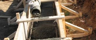
Activities for the construction of any building are preceded by design work, during which the type of foundation base and the required amount of materials for its construction are determined. An important part of the foundation is the reinforcement cage. It increases the strength of the base, dampens tensile forces and bending loads, and also prevents the formation of cracks. To carry out the work, you need to understand how much reinforcement is needed to reinforce a strip foundation, as well as for a columnar and slab foundation. Let's look at the features of the calculations.
Consumption of reinforcement for reinforcing strip foundations
Selection of fittings
The main document according to which steel rods are manufactured is GOST “Hot-rolled steel for the reinforcement of reinforced concrete structures.” Technical conditions. The foundation will require reinforcement class A400/A500 or AIII according to the old markings. These rods have a periodic cross-section with a crescent-shaped herringbone pattern.
The use of rods of classes A240 (AI) and A300 (AII) in the foundation is not allowed. They are easy to distinguish by eye. The first type is characterized by a smooth outer surface. The second has a periodic ring profile. The use of material of higher classes is acceptable, but will lead to an unreasonable increase in financial costs for the construction of the foundation.
The diameters of the reinforcement are prescribed in the joint venture “Concrete and reinforced concrete structures” and “Manuals on the reinforcement of elements of monolithic reinforced concrete buildings”. For convenience, the requirements are summarized in a table.
| Location of fittings | Minimum diameter |
| Longitudinal for strip foundations with a side of less than 3 meters | the total cross-section of all rods is 0.1% of the ribbon cross-section, the diameter of the rods is no more than 40 mm and no less than 10 mm |
| Longitudinal for strip foundations with a side of 3 meters or more | the same, but not less than 12 mm |
| Longitudinal for slab foundations with a side of less than 3 meters | the total cross-section of all rods is 0.3% of the cross-section, rods no more than 40 mm and no less than 10 mm |
| Longitudinal for slab foundations with a side of 3 meters or more | the same, rods no less than 12 mm |
| Transverse (structural) | 6 mm |
| Vertical (structural) with a structure height of less than 80 cm | 6 mm |
| Vertical (structural) with a structure height of less than 80 cm | 8 mm |
For a structure height of up to 150 mm, reinforcement is performed in one horizontal row (rods or mesh). If the height of the foundation is more than 150 mm, it is necessary to provide for laying the reinforcement in two rows. Having received the value of the total cross-section of the working rods according to the assortment from GOST 5781-82*, their number and diameter are selected. After this, they calculate how much reinforcement is needed to make the structure.
What kind of fittings are there?
The fittings are produced mainly from steel. It can be smooth and profiled - with a specially shaped ribbing. The ribbed one is used to distribute the load, the smooth one serves only to give the structure its shape. That is, the main emphasis should be on the quality of the ribbed rod.
Reinforcement can be smooth or ribbed
Not so long ago, plastic reinforcement for foundations appeared on the market. She is actively promoting. But few experts (sellers don’t count) advise using it. If we analyze the properties of one and another type of reinforcement, then in reality all the advantages and disadvantages look something like this:
- Conductive steel - no plastic. It cannot be said unequivocally that conductivity is a poor quality. It can be used, for example, for grounding.
- Plastic fittings are 4-5 times lighter and are produced in coils. This is a fact, but it really only affects the cost of transportation. Since there is no difference in the mass of the reinforced concrete structure, the rod weighs 50 kg or 10.
- Steel rods can be bent directly on the construction site. This cannot be done with polymer products. If necessary, bent sections will be produced at the factory according to your order. It is impossible to do this on the site yourself.
Plastic fittings - a new product on the market
- Plastic is chemically neutral and does not collapse when moisture gets into concrete. This is true. But if the rules are followed (at least 50 mm of concrete from the bars to the surface), the steel reinforcement lasts for decades and does not collapse.
- Steel begins to melt at 600o. Plastics soften at 200-300oC.
- Plastics have better strength characteristics. Not certainly in that way. They stretch more under static loads. If you make a slab foundation reinforced with plastic reinforcement, it will sag after a while: their elongation coefficient is 10-11 times greater than that of steel. It’s the same with a strip foundation: the strip can sag.
In general, it turns out the following: it is better not to use plastic reinforcement for foundations. The idea is too risky.
We are preparing to calculate the amount of reinforcement for the foundation - important points
When planning the construction of a private house, you should pay special attention to the design of the reinforcement grid, which can withstand significant loads on the foundation. A qualified design of the load-bearing grid and the use of the optimal cross-section of the reinforcement makes it possible to ensure the required safety margin of the foundation base, as well as its long service life.
You can independently calculate the reinforcement for the foundation in various ways.:
- using software and online calculators that perform reinforcement calculations after entering operating parameters;
- performing manual calculations based on information about the design features of the foundation, the magnitude of the forces and the lattice parameters.
The foundation takes the load from the mass of the building and evenly distributes it onto the supporting surface of the soil.
The construction of buildings is carried out on various types of foundations:
- tape;
- slab;
- columnar.
Calculation of reinforcement for a strip foundation
Before starting calculations, you should understand the design of the load-bearing frame, which consists of the following elements :
- vertical and transverse rods, between which an equal interval is maintained;
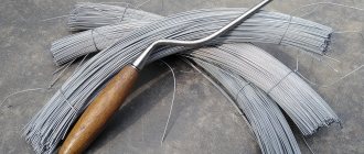
- knitting wire connecting longitudinally located jumpers and vertical rods;
- couplings that provide a strong connection and elongation of reinforcing bars.
Each type of foundation has its own foundation reinforcement scheme, which depends on the following factors::
- soil characteristics;
- building dimensions;
- design features of the structure;
- current loads.
Reinforcement with a ribbed surface is used, which differs:
- section size;
- class;
- level of perceived loads;
- location in the power grid;
- cost.
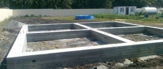
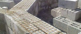
Laying reinforcement in a strip foundation
For various foundations, the following information is determined based on calculations :
- amount of reinforcement for the foundation;
- assortment of vertical and transverse rods;
- total mass of the reinforcement frame;
- methods of fixing steel rods in a load-bearing structure;
- load-bearing lattice assembly technology;
- step of tying reinforcement elements.
It is important to perform the calculation correctly. In this case, the reinforcement for the foundation will provide the necessary margin of safety. Let's consider what initial data is needed for calculations, and also study the methodology for performing calculations for various types of foundations.
Total number of rods
The number of metal rods depends on the perimeter of the foundation.
Before starting construction, the question arises, how much reinforcement is needed for the entire volume of the foundation?
The topic is quite relevant, since if a situation arises when the metal runs out and the work is not completed, downtime will arise, and you will have to pay separately for the delivery of the additional missing batch.
This number is determined as follows:
- The length of the perimeter of the base is found for a building area of 10 * 10 (10 * 4 = 40), the value will be 40 m.
- Since the calculation is required for a 4-rod structure, the previously obtained number is multiplied by 4 (40 * 4 = 160), for a total of 160 m.
The reinforcement bars are overlapped.
To build the foundation of a house measuring 10 * 10 m, 160 m of reinforcement rod is required. However, this value does not take into account the joining of the rods, which is why situations occur when all the steps to determine the quantity were carried out correctly, but the calculated metal was not enough.
The question of how to connect metal rods in the foundation frame is one of the important ones. This is done overlapping with overlap on each other. With a cross section of 10 mm, the length of the connection is made as follows: 10 mm * 30 = 300 mm. The subsequent calculation of the amount of reinforcement is performed based on the number of connecting seams. For more details on calculations, watch this video:
There are two ways to do this. The first involves a well-designed diagram, which indicates the location of the rods and the number of connections. The second method is somewhat simpler: if the reinforcement has already been calculated using the previously described methods, 10 - 15% is added to the resulting number.
Calculation of the amount of reinforcement for a strip foundation
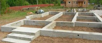
The strip-type base provides increased stability of buildings on various soils. The structure is a concrete strip that follows the contour of the building and is located under the main walls. Reinforcement with steel reinforcement increases the strength characteristics of the concrete base and has a positive effect on its durability. To construct a spatial lattice, you can use reinforcement with a diameter of 10 mm.
Initial data for performing calculations:
- length and width of the foundation base;
- section of reinforced concrete strip;
- spacing between frame elements;
- total number of strapping belts;
- size of the power grid cells.
How much reinforcement is needed for the foundation
? Consider the order of calculations :
- Calculate the total length of the tape outline.
- Calculate the number of elements in the belts.
- Determine the footage of the horizontal bars.
- Calculate the need for vertical rods.
- Calculate the length of the crossbars.
- Add up the resulting footage.
Knowing the total number of joint sections, you can calculate the need for binding wire.
How to calculate reinforcement for a foundation - example calculations
As an example, let's consider how much reinforcement is needed for a 10x10 foundation formed in the form of a monolithic reinforced concrete strip.
To perform calculations we use the following information:
- base width 60 cm, allows you to lay 3 horizontal rods in each belt;
- 2 reinforcement belts are made, connected by vertical rods at intervals of 1 m.
- for a building 10x10 m and a base depth of 0.8 m, reinforcement with a diameter of 10 mm is used.
Consumption of reinforcement for strip foundation
Calculation algorithm :
- We determine the perimeter of the building’s foundation by adding the length of the walls - (10+10)x2=40 m.
- We calculate the number of horizontal elements in one belt by multiplying the perimeter by the number of rods in one tier - 40x3 = 120 m.
- The total length of the longitudinal bars is determined by multiplying the resulting value by the number of tiers 120x2=240 m.
- We calculate the number of vertical elements installed 10 pairs on each side 10x2x4 = 80 pcs.
- The total length of the vertical rods will be 80x0.8=64 m.
- We determine the length of the jumpers, each measuring 0.6 m, installed on two belts (20 per side) - 10x2x4x0.6 = 48 m.
- Adding the length of the reinforcing bars, we get a total footage of 240+64+48=352 m.
Determining the length of steel wire is easy. The number of connections multiplied by the length of one piece of wire equal to 20–30 cm will give the desired result.
Calculation of the amount of reinforcement for a slab-type foundation
The foundation of a slab structure is used for the construction of residential buildings on heaving soils. To ensure strength characteristics, reinforcing bars with a diameter of 10–12 mm are used. With increased mass of buildings, the diameter of the rods should be increased to 1.4–1.6 cm.
You can calculate the amount of reinforcement for the foundation of a slab structure using the following information:
- a spatial frame made of reinforcement is constructed in two levels;
- the connection of the rods is made in the form of square cells with a side of 15–20 cm;
- The binding is performed with annealed wire at each connection point.
Reinforcement diagram for a monolithic foundation slab
To determine the need for reinforcement, perform the following operations :
- Determine the number of horizontal rods in each tier.
- Calculate the total footage of the reinforcing bars that form the cells.
- Add the total length of the vertical supports connecting the tiers.
Adding up the obtained values, we obtain the total need for reinforcement. Knowing the number of joints, it is easy to determine the required volume of steel wire.
Construction of a slab foundation with your own hands.
First you need to prepare the site; this is perhaps the most labor-intensive operation in the construction of a slab foundation. To do this, the top layer of soil is completely removed to a depth determined by calculation. It is recommended to remove and level the last layer manually; this is done in order to avoid unevenness and holes. The pit itself must exceed the dimensions of the foundation by 1-2 m on all sides for ease of work.
Preparing a cushion for a slab foundation made of sand and gravel. Such a cushion is necessary to compensate for the forces of soil deformation, as well as to drain groundwater and prevent its capillary rise to the base of the foundation. The thickness of the cushion depends on the type of soil: on sandy soils it can be 15 centimeters, on saturated clay soils or prone to severe heaving - at least 30 centimeters. Sand is poured into the pit, evenly and distributed over the entire area of the foundation, after which it is thoroughly compacted. For swampy or wet types of soil, part of the cushion will consist of crushed stone, this improves the waterproofing of concrete.
Construction of formwork for a slab foundation. The formwork for a slab foundation must consist of planed boards with a thickness of at least 20 mm, which are connected at the corners using self-tapping screws. From the outside, the formwork is strengthened with struts. Sometimes permanent formwork made of fiberboard is used for slab foundations. It is attached to metal corners and ties, and then struts are also arranged. After the work described above, it is necessary to construct penetrations for communications, and at the same time install formwork around them. Pipes can also be laid and routed through penetrations before the foundation is poured.
Waterproofing of a slab foundation is carried out using a thick polyethylene film, geotextile or roofing felt; it is laid overlapping on the bottom of the pit with an approach to the formwork.
Reinforcement of a slab foundation is a very important stage; the strength of not only the foundation itself, but also the building as a whole will depend on it. For small structures, reinforcement can be done using reinforcing mesh with a mesh size of 10-15 centimeters, and the places where load-bearing walls will be installed must be reinforced with metal rods. If the structure of the structure is more massive, for reinforcement it is necessary to use a rod with a diameter of 10-12 mm, laid in the form of a mesh. The transverse rods are knitted together using wire. Welding of reinforcement is rarely used, since excessive stresses arise at the welding points when the structure moves. The reinforcing mesh must be completely immersed in concrete; for this it is installed on special guides. If the thickness of the foundation is large, then several layers of reinforcement are installed.
Pouring concrete for a slab foundation is done simultaneously, so you will either have to order concrete or mix it very quickly with your own hands. Therefore, pouring must be done by a team of 4-5 people. Concrete is poured into prepared formwork with laid reinforcement, after which it is compacted first using an internal vibrator, and then using a vibrating lath. After punching the concrete and removing voids and air from it, it is smoothed and the surface is leveled.
Drying of the slab foundation occurs within 4-5 weeks. During this time, the concrete gains the necessary strength, after which it is ready for further use. During drying, you need to carefully monitor that the top layer of the foundation does not dry out and is not exposed to excessive moisture; for this, you can use a material with which the concrete can be covered. After the concrete has dried, to improve the thermal insulation properties, the slab foundation can be insulated using polystyrene slabs.
How to calculate reinforcement for a columnar structure foundation
Columnar type foundation is widely used for the construction of various buildings. It consists of reinforced concrete supports of square and round cross-section, installed in the corners of the building, as well as at the intersection points of the main walls and internal partitions. To increase the strength of the supporting elements, ribbed rods with a cross section of 1–1.2 cm are used.
It is easy to calculate the amount of reinforcement for a columnar foundation, taking into account the following data:
- the frame of the square profile support element is formed from 4 rods;
- the lattice of a reinforced concrete support with a circular cross-section is made of three rods;
- the length of the reinforcement elements corresponds to the dimensions of the supporting column;
- The transverse piping of the support column frame is carried out in increments of 0.4–0.5 m.
Algorithm for calculating the consumption of foundation reinforcement
Calculation algorithm :
- Determine the length of the vertical bars in one support.
- Calculate the footage of the cross-bracing elements of one frame.
- Calculate the total length by adding the resulting values.
Multiplying the result by the number of supports, we get the total length of the reinforcement.
Examples of calculating reinforcement consumption
As mentioned above, the number of rods required for reinforcement depends on the type of structure; below are examples of how to carry out calculations for them.
Strip foundation
Let's calculate the amount of reinforcement per 1 m3 of concrete required to reinforce a strip foundation - height 1.2 m, width 0.4 m. For longitudinal reinforcement we use steel rods with a diameter of 12 mm - 14 pcs., for transverse reinforcement, clamps from 8 mm rods - step 30 cm, as well as connecting rods in 60 cm increments.
An example of a reinforcement scheme for a strip foundation.
The procedure for calculating flow according to the diagram above:
- We calculate the cross-sectional area of concrete: 120*40=4800 cm2.
- Sectional area of longitudinal reinforcement: 14*1.131=15.834 cm2.
- We find the percentage of content of longitudinal rods in concrete: 15.834/4800*100=0.329875%, rounded to 0.33%.
- Using the consumption table, we convert the percentages into kg, for this: 0.33/0.1*7.85=25.905 kg.
- To make one clamp, you need 3 m of rod with a thickness of 8 mm (weight of 1 meter is 0.395 kg); in total, 7 clamps will be needed for 1 m3 of foundation, and this is: 7 * 3 * 0.395 * = 8.295 kg.
- You will also need 4 connecting rods with a length of 50 cm and a diameter of 8 mm, in total: 4 * 0.5 * 0.395 = 0.79 kg.
- For 1 m3 of strip foundation concrete with such reinforcement, we get a total of: 25.905 + 8.295 + 0.79 = 34.99 kg of reinforcement.
So, by calculating the required volume of concrete and the number of rods per 1 m3, you can find out how many tons of steel are needed to reinforce the entire foundation. But you should also take into account the number and size of reinforcement overlaps, and calculate the number of additional elements to reinforce corners and other elements.
Monolithic floor slab
Let's calculate using the example of reinforcing a 20 cm thick floor slab, since this is the most common size. The pitch of the reinforcing mesh is 200 by 200 mm, the diameter of the rod is 10 mm, the reinforcement is 14 mm - the pitch is 200 mm.
Schematic example of floor reinforcement.
The procedure for calculating consumption per 1 m3 of flooring according to the scheme:
- For 1 m2 of slab, 20 m of reinforcement is required to knit the upper and lower layers of the mesh.
- 1 m3 of concrete occupies an area of 5 m2, therefore: 5 * 20 = 100 meters - consumption of the rod for knitting the mesh.
- The weight of a meter of 10 mm reinforcement is 0.617 kg. We get, 100*0.617=61.7 kg, the consumption of longitudinal rods for constructing the mesh.
- For additional reinforcements, you will need about 50 meters of a rod with a diameter of 14 mm, total: 50 * 1.21 = 60.5 kg.
- Additional slab elements (space frames, “U” shaped elements), about 20 m of 10 mm steel rods are required, total: 20 * 0.617 = 12.34 kg.
- Total consumption: 61.7 + 60.5 + 12.34 = 134.54 kg of reinforcement per 1 m3 of concrete for a monolithic floor slab.
Thus, it is possible to make calculations for floors of various structures. But at the same time, one should also take into account the cost of joints, reinforcements in the pushing zone, and other additional elements, depending on the shape and features of the structure.
Reinforced concrete column
Let's calculate the consumption for reinforcing a column 300 by 300 mm. Longitudinal reinforcement class A500C with a diameter of 16 mm - 4 pcs., transverse reinforcement A240 - 8 mm. Calculation procedure:
- We calculate the cross-sectional area of the column: 30*30=900 cm2.
- The cross-sectional area of the reinforcement is: 4*2.01=8.04 cm2.
- We calculate the percentage of content of longitudinal rods in concrete: 8.04/900*100= 0.893%.
- We convert the percentages into kg, for this: 0.893/0.1*7.85= 70.1 kg.
- With this cross-section, 1 m3 of concrete in length is 11 meters of column.
- An 11 meter column with a pitch of 25 cm will require about 45 clamps.
- 1 clamp takes 1 meter of rod with a diameter of 8 mm weighing 0.395 kg, which means a total of 45 * 0.395 = 17.775 kg per cube.
- In total, a cube of column concrete will require 70.1 + 17.775 = 87.875 kg of reinforcement.
All calculations for steel consumption are theoretical; each case should be approached individually, taking into account all the existing loads on the structure, since the minimum percentage of reinforcement depends on this, and on it, how much reinforcement will be needed per 1 m3 of concrete. If you have any questions, ask in the comments, we will be happy to help.
Calculation example for a strip foundation of a house 10x10 meters
Initial data:
- tape width - 60 cm, height - 100 cm;
- for such cross-sectional sizes, you need to lay 4 working rods of 14 mm each, two in the top row and two in the bottom (for more information on how this is calculated, see here);
- transverse reinforcement - 6 mm;
- vertical reinforcement - 8 mm;
- a house measuring 10x10 meters with one internal load-bearing wall in the middle.
When calculating the amount of material, it is necessary to take into account:
- thickness of the protective layer of concrete;
- overlapping of rods when extending along the length;
- reserve for corner reinforcement.
The calculation is carried out in the following order:
Working reinforcement
For working reinforcement, the thickness of the protective layer of concrete must be specified according to SP 50-101-2004:
- in the presence of concrete preparation - 4 cm;
- in the absence of concrete preparation - 7 cm.
We assume a layer thickness of 70 mm.
Length of rods in external walls:
L1 = 10 m - 0.07 m*2 (on each side) = 9.86 m - length of one rod;
L = 9.86 m * 4 walls * 2 rods in each row * 2 rows = 157.76 m.
Length of rods in internal walls:
L1 = 10 m - 0.07 m*2 (on each side) = 9.86 m - length of one rod;
L = 9.86 m * 1 wall * 2 rods in each row * 2 rows = 39.44 m.
Adding the values for the outer and inner tape we get: 157.76 +39.44 = 197.2 m.
The overlap size of the rods is taken to be at least 20 diameters of the working reinforcement and at least 250 mm. In this case the overlap is equal to:
l = 14 mm*20 = 280 mm.
Rod length - 6 m. Design length - 5.72 m (less overlap on one side).
Advice! In general, the standard length of reinforcement bars is 11.7 m; the length given here takes into account cutting them in half, because Delivery of 11.7 meter rods is difficult and expensive, but if there is such a possibility, then it is better to bring the reinforcement to the construction site in solid rods.
To calculate the flow rate taking into account the increase, we calculate the percentage increase:
(6 m * 100%)/5.72 m = 104.9%.
To the resulting value we add an additional percentage of reserve for corner reinforcement and other unforeseen expenses, approximately 5%.
We calculate the final length of the working reinforcement with a diameter of 14 mm:
197.2 m * (104.9%+5%) = 216.7 m.
Transverse reinforcement
The step is taken to be no more than 20 diameters of the working reinforcement.
S = 20 * 0.014 m = 0.280 m, take 0.25 m.
We calculate the length of the rod taking into account the protective layer of concrete on both sides:
L1 = 0.6 m (tape width) - 0.07 m * 2 = 0.46 m.
The number of rods in one row is calculated as the perimeter of the tape divided by the pitch plus one.
P = 4 *10 m (external walls) + 10 m (internal wall) = 50 m.
N = (50 m/0.25 m) + 1 = 201 pcs.
In corners and wall junctions, transverse reinforcement is laid twice as often. For each corner or interface, on average, 3 additional rods are needed in each row. The building in question has 4 corners and 2 junctions. We calculate the final number of clamps:
201 pcs + 3 pcs*6 = 219 pcs. - quantity in one row. Two rows will require 438 cross clamps.
In this case, there are no overlaps in length, since the required length of the rod is less than the standard one. We calculate the total length of the rods:
L = 438 pcs * 0.46 m = 201.48 m. It is better to provide a reserve for unforeseen expenses of 2-3%. We get the total amount of material with a diameter of 6 mm:
201.48 m * 103% = 207.5 m.
Vertical reinforcement
The length of one rod is calculated as follows:
L1 = 1m (tape height) - 0.07m*2 = 0.86 m.
The pitch is equal to the pitch of the transverse clamps. Quantity: two on each vertical side. It turns out that the number of vertical rods is equal to the number of transverse rods - 438 pcs.
Total length of reinforcement ø8 (including contingency reserve):
(0.86 m * 438 pcs) * 103% = 388 m.
Calculation of slab thickness
The calculation is carried out according to the joint venture “Design and installation of foundations and foundations of buildings and structures” and according to the manual “Guidelines for the design of slab foundations of frame buildings and tower-type structures” in two stages:
- load collection;
- calculation based on bearing capacity.
Collection of loads includes work to calculate the total mass of the house, taking into account the weight of snow cover, furniture, equipment and people. Values for houses made of various materials can be taken from the table.
| Load type | Meaning | Reliability factor |
| Walls and partitions | ||
| Brick 640 mm | 1150 kg/m2 | 1,2 |
| Brick 510 mm | 920 kg/m2 | |
| Brick 380 mm with insulation 150 mm | 690 kg/m2 | |
| Beam 200 mm | 160 kg/m2 | 1,1 |
| Beam 150 mm | 120 kg/m2 | |
| Frame 150 mm with insulation | 50 kg/m2 | |
| Plasterboard partitions 80 mm | 30-35 kg/m2 | 1,2 |
| Brick partitions 120 mm | 220 kg/m2 | |
| Floors | ||
| Reinforced concrete 220 mm with cement-sand screed 30 mm | 625 kg/m2 | 1.2 - for prefabricated and 1.3 - for monolith |
| Wooden on beams | 150 kg/m2 | 1,1 |
| Roof on wooden rafters | ||
| Metal coated | 60 kg/m2 | 1,1 |
| Ceramic coated | 120 kg/m2 | |
| With bitumen coating | 70 kg/m2 | |
| Live loads | ||
| Useful for residential buildings | 150 kg/m2 | 1,2 |
| Snow | Depending on the construction area according to clause 10.1 of the SP “Loads and Impacts”. The snow region is determined by the SP “construction climatology”. | 1,4 |
Important! The table already takes into account the thickness of the structures. To calculate the mass, all you have to do is multiply by the area
In addition, each load must be multiplied by a safety factor. It is necessary to ensure a reserve for the load-bearing capacity of a concrete structure and to prevent problems in the event of minor errors by builders or changes in operating conditions (for example, a change in the purpose of the building). All coefficients are accepted according to the joint venture “Loads and Impacts”.
For different loads, the coefficient is different and ranges from 1.05-1.4. The exact values are also given in the table. For a concrete foundation using monolithic technology, a coefficient of 1.3 is taken.
Important! If the roof slope is more than 60 degrees, the snow load is not taken into account in the calculation, since with such a steep slope, snow does not accumulate on it. The total area of all structures is multiplied by the mass given in the table and the coefficient, after which, adding, the total weight of the house is obtained without taking into account the foundations
The total area of all structures is multiplied by the mass given in the table and the coefficient, after which, adding, the total weight of the house is obtained without taking into account the foundations.
The basic formula for calculations is as follows:
P1= M1/S,
where P1 is the specific load on the ground without taking into account the foundation, M1 is the total load from the house obtained when collecting loads, S is the area of the concrete slab.
Next, you need to calculate the difference (Δ) between the obtained value and the number given in the table above, depending on the type of soil.
Δ=P-P1
where P is the tabulated value of the bearing capacity of the soil.
M2 = Δ*S,
where M2 is the required mass of the foundation (it is impossible to build a foundation greater than this mass), S is the area of the concrete slab.
The following formula:
t = (M2/2500)/S,
where t is the thickness of concrete pouring, and 2500 kg/m3 is the density of one cubic meter of reinforced concrete foundation.
Next, the thickness is rounded to the nearest larger and smaller multiple of 5 cm. Afterwards, a check is performed in which the difference between the calculated and optimal pressure on the ground should not exceed 25% in any direction.
Advice! If the calculation turns out that the thickness of the concrete layer exceeds 350 mm, it is recommended to consider such types of construction as a strip foundation, columnar or slab with stiffeners.
In addition to the thickness, you will need to select the appropriate reinforcement diameter, as well as calculate the amount of reinforcement for concrete.
Important! If, as a result of the calculation, you get a slab thickness of more than 35 cm, this indicates that the slab foundation is redundant in the given conditions, you need to calculate strip and pile foundations, perhaps they will be cheaper. If the thickness is less than 15 cm, then the building is too heavy for the given soil and accurate calculations and geological studies are needed
Statement of consumption
For purchase and transportation, it is necessary to combine all values into one table.
| ø14 | ø8 | ø6 | |
| Length | 216.7 m | 388 m | 207.5 m |
| Weight of 1 meter according to the assortment | 1.21 kg | 0.395 kg | 0.222 kg |
| total weight | 262.2 kg | 153.26 kg | 46.07 kg |
| Number of rods 11.7 m each | 19 | 34 | 18 |
To obtain the number of required rods, the total length of the required reinforcement must be divided by 11.7 meters (standard rod length).
Assembly Rules
The parameters of the frame for the strip foundation have been determined, you can proceed to the installation processes. First of all, you need to cut the reinforcement into elements along the length. It is clear with vertical and transverse ones. In our example it would be:
- vertical 90 cm;
- transverse 40 cm.
The quantity is calculated taking into account the total length of the trenches. For example, the length of the trenches dug under the walls is 100 m; this figure must be divided by the step of laying the reinforcement. If it is 20 cm, then 100/0.2 = 500 pieces of both types.
As for longitudinal rods, the length of one rod is taken as a basis. It is equal to 11.7 m, taking into account the knitting overlap, a value of 10 m is used. Therefore, in one row of longitudinal rods: 100/10 = 10 pieces. In the case of 5 rows with a pitch of 20 cm, plus two gratings, it turns out that what is required to assemble the frame is: 10x5x2 = 100 pieces of reinforcing rods 10 m long.
Calculation example for a strip foundation of a 6x6 meter house
Initial data:
- tape width - 50 cm, height - 70 cm (shallow foundation on a good foundation);
- we lay 4 working rods of 12 mm each;
- transverse - 6 mm;
- vertical - 8 mm;
- building measuring 6x6 meters without internal walls (only partitions).
Working reinforcement
The thickness of the protective layer is 7 cm.
L1 = 6 m - 0.07 m*2 (on each side) = 5.93 m - rod length;
L = 5.93m * 4 walls * 2 pieces * 2 rows = 94.88 m.
Overlap length:
l = 12 mm*20 = 240 mm. We accept 250 mm.
The length of the rod according to GOST is 6 m. The estimated length is 5.75 m (subtract the overlap). Percentage increase in consumption:
(6 m * 100%)/5.75 m = 104.35%.
The reserve for corner reinforcement and unforeseen expenses is 2%.
94.88 m * (104.35%+2%) = 95.23 m - ø12.
Transverse reinforcement
We calculate the pitch of the rods:
S = 20 * 0.012 m = 0.240 m, take 0.2 m.
rod length:
L1 = 0.5 m (tape width) - 0.07 m (protective layer) * 2 = 0.36 m.
Number of rods in one row:
P = 4 * 6 m = 24 m - the perimeter of the tape.
N = (24m/0.2m) + 1 = 121 pcs.
The foundation has 4 corners, there are no mates, we add additional clamps:
121 pcs + 3 pcs*4 = 133 pcs. - one row.
133 pcs * 2 = 266 pcs. - two rows.
Total length of rods:
L = 266 pcs *0.36 m = 95.76 m.
Contingency reserve - 3%.
95.76 m * 103% = 98.6 m ø6 material needed.
Vertical reinforcement
Length of one rod ø8:
L1 = 0.7 m (tape height) - 0.07 m*2 = 0.56 m.
Number of rods - 266 pcs.
L = (0.56 m * 266 pcs) * 103% = 153.42 m.
Statement of consumption
| ø12 | ø8 | ø6 | |
| total length | 95.23 m | 153.42 m | 98.6 m |
| Weight of 1 meter according to the assortment | 0.888 kg | 0.395 kg | 0.222 kg |
| total weight | 84.6 kg | 60.6 kg | 21.9 kg |
| Number of rods 11.7 m each | 9 | 14 | 9 |
Careful calculation of materials for construction will save time and money.
Calculation of composite reinforcement
Reinforcement made of composite materials began to be used in the Russian construction industry relatively recently, so some nuances regarding this material should be touched upon. Due to the use of glass or basalt fibers in the manufacture, this reinforcing material has significant differences from classical steel reinforcement in terms of strength in the direction of positive qualities. You can clearly evaluate the difference from the table below.
| Characteristic | Steel reinforcement class AIII | Composite reinforcement |
| Replacement of reinforcement diameter with equal strength characteristics, mm. | 8 | 4 |
| 10 | 6 | |
| 12 | 8 | |
| 14 | 10 | |
| 16 | 12 | |
| 18 | 14 | |
| 20 | 16 |
You can learn more about what composite reinforcement is and also about methods of working with it in the article: composite reinforcement, types, characteristics, use.
Based on these data, when using composite reinforcing rods it is necessary to adjust the diameters of the working reinforcement. This means that it is possible to calculate the reinforcement of structures for steel reinforcement, and then change the resulting diameters of the rods according to the data given in the table.
It should be taken into account that composite reinforcement cannot be bent on a construction site and is not welded. If there is a need for bent elements, they must be ordered from the manufacturer according to prepared drawings, since such material can only be bent during the manufacturing process. The rods are fastened to each other using tie wire or plastic clamps.
The calculation of a foundation using composite reinforcement is similar to the calculation for metal reinforcement.
In all other respects, the use of composite reinforcement is no different from standard steel bars.
Carrying out work on reinforcement and subsequent pouring of monolithic building structures requires the master to have certain skills. If you doubt your abilities, it is better to turn to experienced specialists; this will save time and money in case of possible alterations due to possible mistakes of a novice master, and will also protect you from possible emergency situations.
Information on the purpose of the calculator
Online calculator for monolithic strip foundation
designed for calculating dimensions, formwork, quantity and diameter of reinforcement and volume of concrete required for the construction of this type of foundation. To determine the appropriate type of foundation, be sure to contact a specialist.
All calculations are performed in accordance with SNiP 52-01-2003 “Concrete and reinforced concrete structures”, SNiP 3.03.01-87 and GOST R 52086-2003
A strip foundation is a monolithic closed reinforced concrete strip running under each load-bearing wall of a building, thereby distributing the load along the entire length of the strip. Prevents subsidence and changes in the shape of the building due to the action of soil heaving forces. The main loads are concentrated at the corners. It is the most popular type among other foundations in the construction of private houses, as it has the best ratio of cost and necessary characteristics.
There are several types of strip foundations, such as monolithic and prefabricated, shallow and deep. The choice depends on the characteristics of the soil, the expected load and other parameters that must be considered in each case individually. Suitable for almost all types of buildings and can be used when constructing basements and basements.
The design of the foundation must be carried out especially carefully, since if it is deformed, this will affect the entire structure, and correcting errors is a very complex and expensive procedure.
When filling out the data, pay attention to the additional information with the Additional information sign
The following is a complete list of calculations performed with a brief description of each item.
Reinforcement of floor slabs
Floor slabs manufactured at concrete factories have standard dimensions and a load-bearing capacity determined by calculation. Reinforcement of such slabs is carried out with reinforcing mesh and embedded parts according to a project developed by specialized organizations. The parameters of the slabs are indicated by the seller and selected based on the required indicators for a particular building.
Independent production of a monolithic reinforced concrete slab is not possible due to the complexity of carrying out calculations of the structure and formwork itself, and the need to use heavy construction mechanisms and devices in the manufacturing process. A small error in calculations can lead to accidents or destruction of the building, which can endanger human life and health. Therefore, to carry out this type of work, it is imperative to contact specialists.
General information on the calculation results
- Total length of tape
— The length of the foundation in the center of the strip, taking into account the internal partitions.
- Tape sole area
— Area of support of the foundation on the soil. Corresponds to the dimensions of the required waterproofing.
- Outer side surface area
— Corresponds to the area of the required insulation for the outside of the foundation.
- Concrete volume
— The volume of concrete required to pour the entire foundation with the given parameters. Since the volume of concrete ordered may differ slightly from the actual one, as well as due to compaction during pouring, it is necessary to order with a 10% reserve.
- Concrete weight
— The approximate weight of concrete based on average density is indicated.
- Load on soil from foundation
— Distributed load over the entire support area.
- Minimum diameter of longitudinal reinforcement bars
— Minimum diameter according to SP 52-101-2003, taking into account the relative content of reinforcement from the cross-sectional area of the tape.
- Minimum number of rows of reinforcement in the upper and lower chords
— A minimum number of rows of longitudinal rods in each belt to prevent deformation of the belt under the influence of compression and tension forces.
- Minimum diameter of transverse reinforcement bars (clamps)
— Minimum diameter of transverse and vertical reinforcement bars (clamps) according to SP 52-101-2003.
- Spacing of transverse reinforcement bars (clamps)
— The pitch of the clamps necessary to prevent shifts of the reinforcement cage when pouring concrete.
- Amount of reinforcement overlap
— When fastening sections of rods with overlap.
- Total length of reinforcement
— The length of all reinforcement for tying the frame, taking into account the overlap.
- Total weight of reinforcement
— Weight of the reinforcement cage.
- Formwork board thickness
— Design thickness of formwork boards in accordance with GOST R 52086-2003, for given foundation parameters and at a given support spacing.
- Number of boards for formwork
— The amount of material for formwork of a given size.
Purpose of reinforcement
The reinforcement resists loads on the foundation from the soil and the building itself. Strip foundations are a monolithic foundation structure made of reinforced concrete. The base is made directly at the construction site.
Reinforced concrete is concrete, inside of which there is a metal frame made of reinforcement. Metal allows you to withstand lateral loads that create:
from bottom to top - soil heaving processes; from top to bottom the mass of the building. Pure concrete resists lateral loads poorly. Steel embedded inside the structure can make the foundation tens of times stronger.
Under load, each meter of concrete can stretch by 2–4 mm, while steel can stretch from 4 to 25 mm. Concrete withstands compression many times better.
Regulations
Strip foundations in low-rise construction refer to reinforced concrete structures without pre-tensioning reinforcement.
Such foundations are designed and built in accordance with the set of rules SP 52-101-2003. Section 5.2 of the document defines the steel grade, shape and geometric dimensions of the rods. Section 8.3 “Reinforcement” discusses the number and size of reinforcing elements, their relative location in the concrete body. The methods for placing reinforcement and the rules for connecting at intersections are also indicated here.
The information contained in the document is enough to understand how to calculate the reinforcement for the foundation and calculate the amount of material.
Range of metal products
Classes of reinforcing steel For reinforced concrete structures, the following reinforcement is used:
hot rolled, smooth or with a periodic profile (ring or crescent) with a diameter of 6 to 40 mm; thermally and mechanically strengthened with a periodic profile, 6–40 mm; cold-deformed periodic section (3–12 mm). It is recommended to use smooth reinforcement with a class not lower than A-240 (A-I). For ribbed (periodic profile) choose class A-300 and higher. In areas where the temperature drops below 30°C, class A-300 is prohibited from use.
It is preferable to use products with a periodic profile - with tides in the form of rings or a sickle. Irregularities increase the adhesion area of the rods to the concrete and the strength of the entire structure.
Recently, composite reinforcement has appeared on sale. The manufacturer recommends using it instead of steel products.
SP 295.1325800.2017 does not allow the use of composite products for foundations.
Bookmark scheme
Section 8.3 allows you to accurately calculate the reinforcement for the foundation. Code of Rules.
Protective layer In reinforced concrete foundations, a protective layer is provided for steel parts, which provides:
collaboration of all parts; protection of rods from aggressive environmental influences (moisture), chemicals; fire resistance. In soil, the layer thickness (the distance from the rods to any outer edge of the concrete) is chosen to be at least 40 mm. Outdoors, the distance is reduced to 30 mm.
Longitudinal reinforcement
For a side of the foundation up to 3 meters long, it is permissible to use rods with a diameter of 10 mm; if the side exceeds 3 m, no thinner than 12 mm.
The total cross-section of the longitudinal reinforcement bars is chosen to be at least 0.1% of the cross-section of the foundation.
For example, for a tape 40 cm wide and 100 cm high, the cross-section is 400x1000 = 4,000,000 mm². The total cross-section of all longitudinal rods should be 0.1%, i.e. 400 mm².
You can select the required number of rods using the table.
Diameter of the rod, mm Total cross-section of the rods depending on the number of rods, mm 1 2 3 4 5 6 7 8 9 10 75 155 235 315 390 470 550 630 710 12 115 225 340 450 565 680 790 900 1020 14 155 310 460 615 770 925 1080 1230 1385 16 200 400 605 805 1010 1210 1410 1610 1810 According to the table, for a foundation with a cross-section of 40x100 cm you need 6 longitudinal rods of 10 mm or 4 pieces of 12 mm.
The distance between the axes of the longitudinal sections of the reinforcement should not be more than 40 cm, and the number of rods in one level cannot be less than 2. One reinforcement is used only in foundations thinner than 15 cm.