Beton-House.com
Website about concrete: construction, characteristics, design. We combine the experience of professionals and private craftsmen in one place
Concreting a monolithic floor
The first part of this article talked about the types of concrete and their components, and presented the current standards regulating their production. But GOST standards for concrete and reinforced concrete form a much larger list, because documentation for the production of work related to monolithic concreting, as well as the manufacture of concrete products, is also added to it. With the help of the video in this article, we will try to provide as detailed information as possible on them.
- Primary requirements
- Requirements for the manufacture and installation of products
Basic installation errors
When strengthening a slab foundation, the reinforcement scheme is drawn up in strict accordance with technology.
We invite you to familiarize yourself with How to make a foundation from tires for a bathhouse with your own hands: diagram, video instructions
If necessary, this scheme may involve an uneven distribution of rods. Places where it is planned to install load-bearing interior partitions and columns (pressure zones) are subject to additional reinforcement.
The reinforcement is laid in one layer if the thickness of the slab does not exceed fifteen centimeters. In other cases, it is recommended to install a reinforcement cage.
Calculations for a slab-pile foundation are performed separately, taking into account the location of the pile supports and the material from which they are made. In each case of slab reinforcement, the drawing is drawn up according to preliminary calculation data.
Slab parameters
Most often, the reinforcement is laid in two rows, the joint actions of which are ensured by vertical rods. The distance between the rods should be equal to the pitch of the main metal structure. Reinforcement at the ends of the slab is performed with U-shaped clamps; their minimum length is equal to two parameters of the base thickness.
All rows must be covered with rod strapping to ensure reliable perception of torque at the edges of the foundation and to be able to anchor the ends of the longitudinal rods.
Punching zones
At the support points of vertical structures, rods are laid out with a reduced reinforcement pitch. If the rods are laid out across the entire width of the foundation slab in increments of twenty centimeters, then in places where partitions are placed it is recommended to reduce this distance to ten. This will prevent the occurrence of cracks and dents.
When reinforcing a monolithic foundation, the frame elements of the slabs and walls should be tied together. When concreting the base, it is necessary to leave parts of vertically placed rods, which later act as connecting links. Such ends are launched into the base, the edges are bent at the level of two dimensions of the slab height, then they are tied to the main frame.
To provide the foundation with the necessary properties and protect it from destruction, it is necessary to strictly adhere to the reinforcement technology. As a rule, inexperienced builders make common mistakes:
Do not stretch polyethylene material over the poured concrete solution. The laitance leaks out and cracks appear on the surface;
- Having filled a cushion of sand and crushed stone, many neglect to compact it. The foundation shrinks and cracks form;
- on the installed formwork, the cracks through which the mortar mixture flows are not sealed, which leads to the appearance of unevenness;
- poor insulation of the slab from the soil surface will lead to premature destruction of the foundation, and restoration work will be quite expensive;
- It is a mistake to use stones as spacers;
- during installation work, reinforcing bars are fixed in the soil layer, the metal corrodes and quickly collapses;
- Before laying the foundation, a cushion of sand-crushed stone mixture is not poured, which reduces the strength of the slab. Another typical mistake is that only crushed stone is used to construct the cushion, but the minimum percentage of sand content in the cushion under the foundation slab before its reinforcement should be within forty;
- the spacing of the mesh rods exceeds the permissible maximum limit of forty centimeters, or does not at all correspond to the calculated data on load effects;
- there is no protective layer of concrete mortar on the side of the reinforcement ends, and the metal is subject to corrosion ahead of time;
- There are no vertical reinforcing bars under the installation of walls and columns, and the load forces are distributed unevenly.
We invite you to familiarize yourself with the Foundation for a frame bath with your own hands
These are the most serious errors that can clearly have a negative impact on the performance of the foundation. There are also more unobvious features that only experienced specialists can tell you about.
Concrete and reinforced concrete structures
Before talking about individual structures, it is impossible not to mention the document according to which the design and manufacture of all types of concrete and reinforced concrete products is carried out. This is SNiP 52-01*2003 called “Concrete and reinforced concrete structures”.
Primary requirements
Standards 52-01 define the requirements for:
- concrete;
- fittings;
- calculation of structures for strength, deformation, formation and opening of cracks;
- geometric dimensions of structures, the key to correctness of which is formwork;
- protection from environmental influences;
- quality control of structures;
- strengthening and restoration;
- structural requirements for formwork, reinforcement and concreting.
Basic requirements for formwork
SNiP for concreting also provides a list of regulatory documents that define the requirements for:
- fire resistance limit;
- frost resistance;
- waterproof;
- influences and loads;
- limiting deformations (oscillation amplitude, deflections, displacements);
- calculated values of temperature and humidity.
Note! Note that the determination of the strength of concrete of all types, except those that have a special purpose, is carried out according to standards 10180*2012 and 10181-2000. According to GOST, concrete sampling is carried out for the purpose of producing control samples in the form of calibrated cubes, prisms or cylinders, which are examined in laboratory conditions under specially created conditions.
Standardized indicators
| Index | Symbol | Limit values |
| Compressive strength class. Prescribed in all cases. | IN | The digital designation of this indicator corresponds to the compressive strength of the concrete sample (cube), measured in MPa. Depending on the type of concrete, it can be from 0.5 to 120. For example: according to GOST, B7.5 concrete has a strength of about 10 MPa, which corresponds to grade M100. |
| Axial tensile strength class Controlled only in production. It is prescribed when the tensile strength of the structure is of primary importance. | Bt | Axial tensile strength is also measured in MPa, taken within the range of 0.4-6. Other values are accepted only for special massive structures. Testing of concrete samples is carried out in accordance with GOST 22690*2015 Concrete (Non-destructive testing methods). |
| Brand by density | D | This indicator corresponds to the volumetric mass of concrete (average value) in kg/m3. Limits of values, with the exception of prestressing concrete: from 200 to 5000. |
| Waterproof grade | W | This is the maximum value of water pressure that the sample could withstand during testing, which is expressed in MPa • 10-1. The range of values is from 2 to 20. |
| Frost resistance grade | F | The frost resistance indicator corresponds to the number of cycles of sequential freezing and thawing that the sample can withstand without signs of destruction. Accepted from 15 to 1000. |
If necessary, additional indicators can be established for concrete: thermal conductivity, fire resistance and temperature resistance, corrosion resistance and the level of biological protection.
The quality indicators of concrete are ensured by the designed composition of the mixture, the technology of its preparation and construction of the structure. Therefore, they are controlled both during the production of concrete and in the structure itself.
Note! There is such a thing as “age of concrete”. This indicator is responsible for the strength of the stone in axial tension and compression. During design, it is assigned depending on the actual loading time of structures. In this case, the methods of their construction and the specific conditions under which the concrete hardening process occurs must be taken into account. If the project does not contain individual data, then the standard design age of concrete is assumed to be 28 days.
Design requirements
SNiP 52-01*2003 is the main document that defines the requirements for structures made of concrete and reinforced concrete. Moreover, the requirements apply not only to the structures and concrete themselves, but also to the reinforcement used and calculations.
It also provides rules that should be followed both during the manufacture or construction of structures and their operation. However, for certain types of structures, as a development of this document, additional standards have been developed for certain types of structures.
Reinforcement
Requirements for fittings are general.
When designing buildings, it is allowed to use the following types:
- Steel:
- Smooth and periodic hot-rolled, with a diameter from 3 mm to 80 mm (class “A”);
- Periodic, thermomechanically strengthened, with a diameter from 6 mm to 40 mm;
- Smooth and periodic cold-deformed – with a diameter from 3 mm to 12 mm (class “B”);
- Twisted (reinforcing ropes) – with a diameter from 6 mm to 15 mm (class “K”).
- Composite (non-metallic) reinforcement.
- Fiber (fiber or rods).
- Fine mesh meshes.
- Sheet or profiled steel (for steel-reinforced concrete structures).
The choice is made depending on design solutions, the nature of the perceived loads and operating conditions.
The main indicator for reinforcement is tensile strength. Non-metallic reinforcement and fiber are also subject to requirements for adhesion to concrete and resistance to alkali attack.
A separate chapter of these rules is devoted to the protection of reinforcement in concrete through a protective layer.
In this case, the following must be ensured:
- Joint work of reinforcement and concrete in a structure;
- Anchoring of reinforcement to ensure connections at nodes;
- Protection of fittings from corrosion;
- Fire protection of structures.
The protective layer of concrete plays an important role
Attention! The thickness of the protective layer of concrete is taken in accordance with:
- The role of reinforcement in construction;
- Type of construction;
- Type of reinforcement and its diameter.
But there cannot be a protective layer of concrete less than 10 mm!
According to SNiP, reinforced concrete is reinforced in such a way that the joint work of reinforcement and concrete is ensured, it is possible to carry out high-quality concreting of structures, and subsequently join their reinforcement.
Compaction of concrete during monolithic concreting
The pitch between the rods depends on the filler fraction, the diameter of the reinforcement and its location, as well as the method by which concrete is laid and compacted. But this distance cannot be less than 25 mm!
In this case, it can be arranged in bunches, forming a conditional rod. The distance between such beams is taken to be no less than their diameter.
Materials
Reinforcement is the strengthening of a concrete block from the inside using various materials. Rods or fibers can be used that, when the block is stretched, do not allow it to crack.
In practice, reinforcement materials can be divided into 3 groups:
- metal rods,
- composite reinforcement,
- fiber.
Steel bars
The standard length of a steel bar for reinforcing concrete structures is 11.75 m. The reinforcement can have different diameters and grades. Depending on the marking, the rods are joined into a reinforcing frame by welding or knitted with wire.
In the mass of concrete, the connection between the steel rods and the mortar is quite strong due to the corrugation on the rod. The steel frame inside the monolith redistributes the loads and keeps the concrete from cracking, since the metal has greater tensile strength. At the same time, concrete, in turn, protects the metal from corrosion.
Steel reinforcing frameComposite material
Such fittings have a fairly wide range of source materials, increasing almost every year. To date, fiberglass and basalt plastic rods with spiral wrapping, simulating the periodicity of the steel reinforcement profile, are more or less used.
In addition, the construction market offers polyethylene rephthalate and hydrocarbon fittings, which have not yet received widespread popularity. The undeniable advantage of the composite is its low weight. But when constructing foundations or retaining walls, this advantage is of little importance, but the strength characteristics are very important.
Composite reinforcement is usually used in horizontal building elements supported on the ground
Fiber fiber
Fine material (fiber) is added to the solution at the mixing stage. Moreover, the fiber itself can have different diameters and lengths.
Fiber is made from fiber based on:
- become,
- glass,
- polypropylene compounds,
- basalt.
Fiber fiber to enhance the tensile strength of concrete
Features and purpose of floor slabs
Reinforced concrete floor slabs are considered one of the important components of buildings. Their main role is to redirect loads from higher-lying building systems, decoration, furniture, electrical appliances to the walls or foundation of the building. In addition, they are used as interfloor ceilings - they divide the structure into floors, a basement, and also an attic space.
The depth of support of the floor slabs is determined in connection with their type, and the material from which the building is made must also be taken into account. However, 120 millimeters is considered a suitable size - in design and industrial documentation for the construction of facilities, this value is usually used.
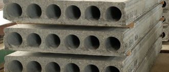
Among buyers, developers use the following brands of hollow-core slabs in maximum demand:
- PCs are round-hollow products produced according to the formwork process, which involves the use of specialized configurations for the purpose of pouring concrete.
- PB are innovative reinforced concrete products made using a permanent formless molding method.
In individual housing construction, oscared slabs are used more, the layer of which is 160 millimeters, in contrast to the typical one, with a width of 220 millimeters. They are also produced according to formless (3.1PB and 1.6PB) and formwork (PNO) technological processes. In addition, manufacturers make ribbed reinforced concrete products, which are characterized by high rigidity and stability to mass overloads due to the presence of longitudinal and transverse ribs. They are usually used to cover production items.
It is very rare to find solid reinforced concrete slabs. This is due to their narrow specialization due to their significant weight. However, they have high strength properties.
How to avoid mistakes when creating a reinforcing frame
Mistakes can be made at any stage of construction; foundation reinforcement is no exception in this case. Even the slightest defects can contribute to the destruction of the slab base or complicate the concreting process. Therefore, it is necessary to learn in more detail what mistakes are made at the reinforcement stage in order to completely avoid them or minimize them.
- The most important mistake when reinforcing a foundation slab can be called incorrect calculations of the expected load on the foundation or their absence. Indeed, on the basis of these data, the dimensions of the reinforcing bars are selected and the layout of the reinforcement is determined.
- The reinforcement bars are connected end-to-end. This method cannot guarantee the strength of the structure, so it is recommended to overlap the elements; the length should be at least 15 diameters.
- During the process of laying the reinforcing frame, the rods are located in close proximity to the soil or stuck into it. As a result of heaving or movement of the soil, the reinforcement becomes embedded in the ground, which leads to the formation of corrosion on the rods. This phenomenon reduces the strength of the frame and the entire base.
- Failure to comply with the rules for the location of rods can also cause destruction of the slab. The recommended distance between the rods should be no more than 40 cm, and in some situations this parameter is reduced to 20 cm.
- If the ends of the reinforcement do not have a protective coating, then corrosion of the elements may occur under the influence of moisture from the concrete solution.
- Proper reinforcement under load-bearing walls and in the corners of the building is of great importance.
- The installation of the frame is carried out not on clamps, but on wooden blocks or other non-standard elements. They not only violate the integrity of concrete, but also promote the penetration of moisture into metal elements.
Foundation slab reinforcement
Reinforcing the foundation slab is a very important and complex stage. But if you follow the rules and accurately carry out the calculations, you can carry out this process yourself.
Structures made of concrete and reinforced concrete
The manufacture of any structure using concrete includes three main stages of work: installation of formwork, installation of reinforcement and concreting itself. Any products: both prefabricated and monolithic, made from all types of concrete specified in GOST 25192 (GOST does not apply to special concrete), must meet the requirements of standard 13015-2012.
Concrete quality control on a construction site
This document summarizes all technical requirements for concrete and reinforced concrete products for construction. Determination of the strength of concrete is regulated by another standard. It is carried out using control samples, for which concrete samples are taken (GOST 10180-2012).
Requirements for the manufacture and installation of products
The most important requirement for any structure is that at the time of operation, its strength in fact must correspond to the design strength:
- In prefabricated products, the strength of concrete must correspond to the design indicator already at the time of delivery to the consumer.
- In monolithic structures, stripping strength is also important - that is, strength at the time of removing the formwork.
Concreting the walls of the pool in inventory formwork
- Lifting of concrete structures is carried out either through mounting loops or using devices that must be provided for by the project. Lifting and moving conditions must be such as to prevent rotation, swinging, overturning of the structure, or its destruction. This applies not only to the concrete surface, but also to mounting loops and reinforcement outlets.
- The construction of buildings made of prefabricated reinforced concrete is always carried out according to the project - or rather, that part of it that is responsible for the execution of the work. The PPR provides for the technological sequence of assembly, as well as a set of measures to ensure the accuracy of the spatial position of structures, their stability, and, of course, the safety of installation work.
- When structures are concreted on site, the project provides for a sequence of work related to stripping, further rearrangement of formwork, and concreting. When monolithic concreting, the main attention is paid to measures that exclude the formation and opening of cracks in concrete.
Installation of a building frame made of prefabricated elements: a crossbar resting on column consoles
Attention! The concreting processes and requirements for them are set out in more detail in SNiP 3.03.01 entitled “Load-bearing and enclosing structures”. It applies to all work related to the construction of monolithic structures, underwater concreting, shotcrete, as well as the construction of enclosing and load-bearing structures made of precast reinforced concrete and concrete blocks.
Advantages and disadvantages of monolithic frame technology
Monolithic reinforced walls have the following advantages:
- the one-piece construction without seams is strong and reliable, it does not blow through, and temperature bridges do not form;
- a smooth, even surface allows you to begin finishing work without prior preparation;
- building construction in a short time;
- monolithic houses have an open layout;
- increased service life of reinforced concrete structures;
- complex architectural curved elements and arches are made quite easily.
Disadvantages of monolithic walls:
- low sound insulation;
- mandatory wall insulation;
- the ability of concrete to conduct vibrations.
Advantages and disadvantages
Advantages of prefabricated floor slabs:
- quick installation;
- low cost;
- strength;
- long service life;
- ease of installation using mechanization;
- decent level of sound insulation.
Cons: impossibility of installation without the use of special equipment and the presence of seams between products.
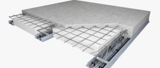
In some cases, when it is not possible to use products with template parameters, it is necessary to use a monolithic floor slab , which is prepared on site independently, without the use of construction equipment. She is characterized
- high reliability;
- the ability to cover any area without seams;
- long service life, about 100 years;
- fire safety.
But there are also negative aspects: the solution takes a long time to harden (about 4 weeks) and the need to install additional supports.
Rules for reinforcing a slab foundation
The basic requirements for a monolithic slab are given in 52-101-2003. They contain recommendations on the location and knitting of reinforcing mesh, and what supports to use to provide a lower protective layer. The use of rods with flaking rust is not allowed.
The periodic cross-section rods provide high adhesion, and the binding wire is more reliable than plastic clamps. However, reinforcement should begin in stages: choosing a rational scheme, calculating the cross-section of the rods, fixing the frames in space using special elements.
Reinforcement schemes
The recommendations of SP 63.13330 for reinforced concrete structures have a special section on the manufacture of main load-bearing structures (10.4). In particular, the following requirements are specified for a slab foundation:
- the reinforcement is laid in two directions (mesh with a maximum cell size of 30 x 30 cm), connected by wire knitting or welding;
- the meshes are placed as close as possible to the top and bottom edges, taking into account a protective layer of 3 cm;
- Using U-shaped clamps, the mesh rods are tied together at the ends;
- in places where monolithic walls and columns are installed, vertical rods are released or anchored with hooks to strengthen the slab;
- under load-bearing walls, the cell pitch decreases compared to the rest of the slab;
- It is allowed to discharge the mesh cell in the central part to the minimum permissible percentage of reinforcement (0.3%).
The grids can be positioned correctly taking into account the lateral protective layers (minimum 4 cm between the rod and the formwork), the location of the communication input nodes (relevant for non-buried slabs).
In practice, for low-rise cottages the following scheme is used:
- mesh of 8 mm reinforcement in the top layer;
- similar mesh in the bottom layer;
- reinforcement of USP ribs or a smooth slab (thickness 30 cm or more) with frames around the perimeter of 10 - 14 mm periodic cross-section rods.
This is due to the absence of heaving forces when using a warm blind area, ring drainage around the foundation, replacing soil with non-metallic materials to a depth of 40 cm. The recommended cell size in the discharged part is no more than 1.5 of the slab thickness, under walls 10 x 10 - 20 x 20 cm In the absence of a footing, the lower protective layer increases to 5 - 7 cm.
Openings
In non-buried slabs it is impossible to do without openings in the monolithic structure for the entry of utility systems. This issue is very poorly described in the specialized literature. An individual developer should refer to the design guidelines for reinforced concrete buildings:
- cutting holes in welded mesh with bending the rods upward;
- edging of openings larger than 30 cm with rods 10 - 14 mm diagonally located to the mesh cells;
- There is no need to reinforce the perimeter of holes smaller than 15 cm.
In deep slabs there are no communication entry nodes by default. To increase the maintainability of engineering systems, sewerage and water supply are run through the basement walls.
Plate/tape interface
It is possible to correctly install reinforcement bars in the formwork of a buried slab foundation with a basement, taking into account the following conditions:
- walls on a recessed slab are prohibited from being placed close to its edges; the minimum perimeter offset is equal to the thickness of the foundation strip (from 10 to 40 cm);
- The anchoring scheme for the interface between the tape and the monolithic basement wall has several options.
Reinforcement outlets in the slab under the walls.
For example, a U-shaped clamp can be extended upward from the slab, the distance between the rods of which corresponds to the size of the tape frame, in order to subsequently connect these two structures. In addition, you can tie rods bent at right angles to the lower and upper mesh of the slab and extend them 40 - 60 cm outwards in the same way as the previous option.
If the project does not have a rigid connection between the tape and the wall with a deep slab, in these places the mesh is reinforced with U-shaped clamps to avoid pushing through.
Depth of the establishment on the walls
The minimum support of floor slabs is regulated by regulatory documents. It depends on:
- Type of building - industrial, administrative or residential.
- Thickness of a brick load-bearing wall.
- Types of load - dynamic or static.
- Load sizes - point and distributed.
- Lengths of reinforced concrete products.
- Dimensions of the overlapped span.
Accurate data on the size of the overlap is obtained using calculations by design engineers; they must fit within the standard of 9-12 cm.
Elements of interfloor ceilings are produced in 2 sizes:
- constructive, which is equal to the distance between the ends of the ceiling slab (net length);
- modular - planned span width.
Basic installation errors
To provide the foundation with the necessary properties and protect it from destruction, it is necessary to strictly adhere to the reinforcement technology. As a rule, inexperienced builders make common mistakes:
Do not stretch polyethylene material over the poured concrete solution. The laitance leaks out and cracks appear on the surface;
- Having filled a cushion of sand and crushed stone, many neglect to compact it. The foundation shrinks and cracks form;
- on the installed formwork, the cracks through which the mortar mixture flows are not sealed, which leads to the appearance of unevenness;
- poor insulation of the slab from the soil surface will lead to premature destruction of the foundation, and restoration work will be quite expensive;
- It is a mistake to use stones as spacers;
- during installation work, reinforcing bars are fixed in the soil layer, the metal corrodes and quickly collapses;
- Before laying the foundation, a cushion of sand-crushed stone mixture is not poured, which reduces the strength of the slab. Another typical mistake is that only crushed stone is used to construct the cushion, but the minimum percentage of sand content in the cushion under the foundation slab before its reinforcement should be within forty;
- the spacing of the mesh rods exceeds the permissible maximum limit of forty centimeters, or does not at all correspond to the calculated data on load effects;
- there is no protective layer of concrete mortar on the side of the reinforcement ends, and the metal is subject to corrosion ahead of time;
- There are no vertical reinforcing bars under the installation of walls and columns, and the load forces are distributed unevenly.
These are the most serious errors that can clearly have a negative impact on the performance of the foundation. There are also more unobvious features that only experienced specialists can tell you about.
Selection of fittings
Three types of reinforcement are used for construction work:
- Reinforcement with a smooth surface (A240), used for reinforcement in the vertical plane. Not recommended for strengthening monolithic slabs;
- Brand A300 (diameter within 10-12 mm). The surface of the rods is covered with ring notches;
- Brand A400. The rods have a crescent-shaped profile. Thanks to the increased working diameter, it is best suited for reinforcing slabs.
Before reinforcing a monolithic foundation, it is necessary to calculate the optimal cross-section of the rods. The reinforcement mesh consists of two layers, the elements of which are located at right angles to each other. The lower and upper rows are connected by means of vertical clamps. Knowing the cross-section of the concrete slab, you can calculate the cross-section of the reinforcing mesh bars running in one direction: it should be about 0.3% of the total area of the monolithic slab.
If the width of one of the sides of the foundation is less than 3 meters, the minimum diameter of one rod is 10 mm. For more massive slabs, it is often sufficient to use reinforcement with a diameter of 12 mm. The maximum diameter of the rod for the plate is 40 mm.
How is floor reinforcement carried out?
In order for the reinforcing mesh to be correctly placed in a monolithic slab, it is necessary to take into account the load that affects the platform. The pressure on the monolith comes from top to bottom and is evenly distributed over the entire surface of the slab. The upper part of the monolith is under the influence of compressive loads. And the lower one is stretching. The rods that are used to create the mesh are necessarily tied together with wire or fastened together by welding. The upper part of the monolith includes a mesh of thin rods, and the lower part of thicker ones.
Common mistakes when reinforcing
There are frequent cases of errors leading to disruption of technology and reduction of operating time. These include:
- there is no polyethylene protective film on the surface of the erected monolithic slab (due to the outflow of water when the concrete hardens, the surface of the base dries out excessively, as a result of which cracks form);
- the prepared sand and gravel substrate is not compacted (distortions and cracks);
- when forming the formwork system, cracks are not sealed, which leads to leakage of the concrete mixture and a reduction in the optimal water level in the solution;
- there is no waterproofing over the equipped substrate (reduction of the water level in the poured solution);
- reinforcement bars are placed directly into the ground (corrosion of the material occurs in the shortest possible time, violating the integrity of the structure and the purpose of reinforcing the base);
- non-compliance with recommendations on the dimensions of fractions of reinforced frames (voids are formed);
- when arranging column elements, the reinforced frames are not fastened to the rods of the columns, which leads to an uneven distribution of loads on the constructed foundation;
- lack of a protective layer (premature corrosion of metal elements).
Watch the video on how to avoid mistakes when laying reinforcement and further pouring the foundation.
https://youtube.com/watch?v=GLqVVVe0yrM%3F
Excavation
The soil is marked according to design standards, increasing its perimeter by 50 cm on each side for the installation of a drainage system
- The soil is marked according to design standards, increasing its perimeter by 50 cm on each side for the installation of a drainage system. It is worth remembering that the slab itself should protrude beyond the walls of the future house by 10 cm on each side.
- Pegs are driven into the ground and a marking cord is pulled. The axes of the future slab should also be drawn.
- The soil is removed from the pit to a depth of 60 cm. At the same time, you should carefully monitor the quality of the soil being removed. If early digging of soil is observed on a building site, then the loosened soil must be removed layer by layer until you reach layers untouched by a shovel. Here, according to the instructions, you will have to remove layers of soil around the entire perimeter of the pit in order to completely level it. After this, the bottom of the pit is compacted and filled with sand to the design level of the pit. If this is not done and the foundation is mounted on soft soil, then the force of the house’s pressure on the slab will simply break it over time precisely in the place of loose soil.
- A drainage system is laid around the design base area in the form of special perforated pipes with their slope towards the storage well or central storm drain.
- Then you should lay a layer of crushed stone 20 cm thick and carefully compact it according to the principle of laying a sand cushion.
- Now we install the formwork from high-quality wooden panels. Their height should be at least 40 cm. It is advisable to clean the inner walls of the formwork. The formwork is fastened with bolts, screws or self-tapping screws. From the outside, the wooden frame can be supported with wedges for greater stability.
What is the need for reinforcement?
In order to increase the strength of concrete and reduce its quantity, reinforcement is used. In theory, any material can act as reinforcement. But in practice, steel and composite are most often used.
A composite is a complex of materials. The basis can be basalt or carbon fibers, which are filled with polymer. Such fittings are lightweight and not subject to corrosion.
Steel, compared to composites, has much greater strength and relatively low cost. In the process of reinforcing monolithic walls, channels, angles, I-beams, corrugated and smooth rods are used. In the case of creating complex building structures, metal mesh is used for reinforcement.
Reinforcement comes in different shapes. But most often you can find the rod one on sale. In the construction of low-rise buildings, corrugated rods are usually used. They have a low price and excellent adhesion to concrete, which makes them very popular among buyers. Steel rods, which are used in the construction of monolithic structures, usually have a diameter in the range of 12-16 mm.
What reinforcement is needed for a slab foundation
Any rod used in the foundation frame must comply with the requirements of GOST 5781 of 1982. However, reinforcement, like most structural materials, has a classification:
- AIII – corresponds to the markings A400 and A500, has a variable cross-section, popularly called “corrugated”;
- AII – corresponds to the current class A300, the cross-section is periodic, discharged;
- AI – new A240 marking, smooth profile.
For the foundation, reinforcement A400 (AIII) is used, it has a crescent-shaped profile.
On sale you will most often find rods of class A500C (for welded mesh, frames) or A500. Reinforcement with index C at the end is suitable for welding and knitting, without index - only for knitting.
We recommend reading in more detail: What reinforcement is needed for the foundation.
Due to the complexity of calculations and the small dimensions of buildings in low-rise construction, a simplified scheme is recommended. Two grids at a distance of 10 cm vertically with at least identical cells. If the developer wants to save on pouring the slab, the calculation should be ordered from specialists who will calculate the minimum required reinforcement, use thin reinforcement in the center of the foundation, strengthen the perimeter, and the places where the internal walls pass.
If the foundation dimensions are more than 3 m on any side of the slab, it is recommended to use rods of at least 12 mm. To determine the minimum possible cross-section, the following method is used:
- calculation of the slab cross-section - length multiplied by thickness (for example, 6 m x 0.3 m);
- calculation of the minimum allowable cross-sectional area of the rod - the previous figure is divided by the minimum percentage of reinforcement (0.3% for concrete B20, 0.15% for grade B22.5, 0.1% for grade B15), for this example 1.8 m²/0 .15 = 27 cm²;
- calculation of the reinforcement area in each row - the result obtained is divided in half (in the example 27/2 = 13.5 cm²);
- determination of the minimum permissible cross-section of a rod depending on the mesh pitch (13.5 cm² / 31 rods every 20 cm for a slab 6 m long = 0.42 cm²;
GOST 5781 contains a table of assortments with reinforcement sections of different diameters. For example, for rod diameters 14 mm, 12 mm, 10 mm, this value will be 1.54 cm², 1.13 cm², 0.785 cm², respectively. Thus, even 10 mm reinforcement provides twice the reinforcement percentage compared to the minimum. Mating is done in the building spot after laying out in rows.
Template for laying reinforcement.
Then it is necessary to correctly calculate the total number of rolled metal products of each diameter. The rods are sold in 11.7 m lengths; the overlap for longitudinal anchoring is 40 reinforcement diameters. The length of the workpiece for each U-shaped clamp is equal to 5 dimensions of the slab thickness, their number coincides with the total number of longitudinal and transverse rods in one mesh. You can convert the length into kilograms using tables from the same GOST, but each construction market has similar conversion tables.
The upper mesh is laid on supports; the most popular in private construction are:
- spider - a U-shaped clamp with legs curved in opposite directions;
- the supporting frame is a lattice curved at a right angle.
The length of each of them is calculated individually, taking into account 2 pcs/m².
The spider is made of reinforcement with a diameter of 8 mm; such elements must be made in advance for laying the upper mesh.
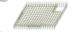
Reinforcement scheme
An example of a diagram (drawing) of reinforcement for a slab foundation.
Reinforcement of a reinforced concrete slab is carried out unevenly: additional reinforcement is required in places where walls or columns support. Such areas are called squeeze zones. The reinforcement is laid in one layer with a slab thickness of 150 mm or less. If the value is more than 150 mm, reinforcement is performed with frames. As an example, it is necessary to consider the main components of the structure.
Basic slab width
Here the scheme is a grid with a constant cell size. The pitch of the rods in both directions should be the same. Depending on the design load, it is taken within the range of 200-400 mm. For brick houses, a reinforcement pitch of 200 mm is suitable; for lighter frame houses, rods can be laid less frequently. It is important to take into account that according to the joint venture “Concrete and reinforced concrete structures”, the distance between the rods should not exceed the thickness of the slab by more than 1.5 times.
Slab reinforcement diagram.
Most often, the rods are laid in two rows: upper and lower. Their joint work is ensured by the installation of vertical rods. The pitch of such rods can be equal to the pitch of the main reinforcement or taken twice as large.
The slab is reinforced at the ends with U-shaped clamps.
According to SP 63.13330.2012 (clause 10.4.9), at the ends the slab must be reinforced with U-shaped reinforcement bars, the length of these bars must be equal to 2 times the thickness of the slab or more. The rods connect the upper and lower rows of reinforcement and provide the perception of torques at the edge of the slab and the anchoring of the ends of the longitudinal reinforcement.
Attention! The reinforcement should be recessed into the concrete by 20-30 mm on all sides: from below, from above, from the ends. Otherwise, accelerated corrosion of the reinforcement and structural destruction are possible.
Punching zones
In places where load-bearing vertical structures are supported, the layout changes - the reinforcement pitch is reduced. For example, if along the main width of the slab the rods were laid every 200 mm, then under the walls it is recommended to use a step of 100 mm. This will avoid excessive pushing and cracking.
Interface area with a monolithic basement wall
The design of the slab allows it to be made flush with the ground surface, but if a basement is planned for the building, its laying depth will depend on the height of the room. In this case, it is necessary to ensure that the base and walls work together.
Reinforcement outlets in the slab for mating with monolithic walls.
To properly reinforce the foundation, it is necessary to tie together the frames of the monolithic wall and the slab. When pouring the foundation, outlets are left in the form of vertical rods; they will be the connecting link. The ends of the outlets are launched into the body of the slab (they are bent at the end to 2 heights of the slab and knitted to the main frame).
For convenience and accurate calculation of materials, a drawing is made that shows a reinforcement diagram, including data on the distance between the rods and their diameters.
Selection of fittings
When manufacturing steel reinforcement, we are guided by GOST 5781-82*. For a reinforced concrete monolithic slab, rods of class A400 and A500 are used (or in the outdated version All). To avoid mistakes, you need to know how to distinguish rods of different classes visually:
- A240 (Al) has a smooth surface;
- A300 (All) is characterized by a periodic profile with a ring pattern;
- A400, A500 (Alll), the one that is needed, has a periodic profile that forms a “herringbone” (crescent).
A500 fittings are manufactured in accordance with GOST 52544-06.
Important! The use of fittings of lower classes is not allowed.
We recommend: What reinforcement is needed for the foundation.
Order of reinforcement and filling
Formwork installation
Reinforcement of floors begins with the installation of formwork. The following requirements are imposed on the formwork: it must withstand the weight of the raw mixture without visually deforming. This is a fairly large load; with a layer of concrete of 200 mm it will be 500 kg per square meter. Therefore, the formwork design must be quite impressive. For panels you can use plywood with a thickness of 18...20 mm, for beams, racks, crossbars you can use timber with a section of 100x100 mm.
You can use professional formwork. Its advantages are that it is designed for high loads; it includes telescopic stands that can withstand significant weight and allow you to adjust the level. This is quite expensive equipment, but now you can find a company that rents out both formwork and racks.
The formwork assembly diagram is easy to find in the literature, and if you take professional formwork, then instructions are attached to it. The main thing is to check the horizontal position after assembly using a level or other available means.
Installation of fittings
Plastic clamps are necessary to create a protective layer of reinforcement in the lower part of the ceiling.
The reinforcement is done in this way: we lay the bottom row on clamps - special plastic supports 25-30 mm high to create a protective layer. We place the rods with the same spacing, parallel to each other. We place the next row on them at an angle of 90? and tie with knitting wire at each intersection. Then we install the mesh separators, bend them, and tie them with the same spacing. The drawing given here will tell you which one. The reinforcement of the floor at the edges is supplemented with reinforcements. Longitudinal and then transverse reinforcement bars are laid on the separators and U-shaped reinforcements. The upper level of the finished reinforcement should be 25-30 mm below the upper plane of the formwork. The assembled reinforcement should be a fairly rigid frame that can withstand the weight of a person without much deformation.
Fill
After the reinforcement is completed, you can begin pouring. This work is best done using a concrete pump, making sure to compact the mixture using a special deep vibrator. It is advisable to fill it in one go. As concrete hardens, it shrinks. The faster the drying, the greater the shrinkage, which can lead to the appearance of microcracks. To prevent this from happening, you need to wet the surface of the hardening slab with water for 2-3 days. This is best done by spraying. But you shouldn’t pour it on a rainy day either; it is recommended to protect the fresh mixture from precipitation. The slab must dry for 30 days, only after which the formwork can be removed.
General recommendations for reinforcement
In order to carry out high-quality reinforcement of a concrete structure, general rules must be followed, taking into account construction technology and the properties of the materials involved. In private construction, they are often neglected, without accurate calculations and drawing up a detailed design, since one- and two-story houses do not place serious loads on the foundation. The reinforcement is laid according to schemes already used earlier, which saves time. In such cases, it is sufficient to comply with the minimum requirements specified in SNiP.
A monolithic reinforced foundation has a sufficient level of strength for the construction of multi-story structures. True, to create the foundation for a high-rise building, a more complex technology is used, which involves the use of several types of reinforcement, accurate calculations of slab dimensions and soil characteristics.
CENTRAL INSTITUTE OF TYPE DESIGN
Recommended for publication by the section of the theory of reinforced concrete and reinforcement of the NTS NIIZHB of the USSR State Construction Committee.
A manual for the design of concrete and reinforced concrete structures made of cellular concrete
(to SNiP 2.03.01-84. Concrete and reinforced concrete structures)/NIIZhB, TsNIISK im. Kucherenko State Construction Committee of the USSR. - M.: CITP Gosstroy USSR, 1986.
Contains basic provisions for the design of concrete and reinforced concrete structures made of cellular concrete. Data on the materials used in these structures, recommendations for calculations and design requirements are provided. Calculation examples are given.
For engineering and technical workers of design organizations.
When using the Manual, it is necessary to take into account the approved changes in building codes and regulations and state standards published in the journal “Bulletin of Construction Equipment”, “Collection of Amendments to Construction Codes and Rules” of the USSR State Construction Committee and the information index “State Standards of the USSR” Gosstandart.
Laying reinforcement in the pit
Many owners prefer to carry out all reinforcement work directly in the prepared pit. This is, of course, advisable if you look at it from the point of view of saving time. This way you won’t have to move the prepared reinforcement structure from the work site and lay it in the foundation.
But such operations often damage the compacted pad and the waterproofing of the base itself, allowing moisture from the soil to gradually destroy the entire foundation of the structure.
It is better to lay the prepared lower chord with connected supports in a pit, and there, in place, make a solid frame, connecting the upper ends of the supports and the outer reinforcement belt.
In this case, before laying the lower chord, it is worth equipping the sides of the pit with formwork so that the reinforcement is immediately carried out firmly. And the metal frame of such a foundation will not require additional modifications in the form of alignment or displacement.