The monolithic floor slab has always been good because it is manufactured without the use of cranes - all work is carried out right on site. But despite all the obvious advantages, today many refuse this option due to the fact that without special skills and online programs it is quite difficult to accurately determine such important parameters as reinforcement cross-section and load area.
In this article, we will help you study the calculation of the floor slab and its nuances, and also introduce you to the basic data and documents. Modern online calculators are a good thing, but if we are talking about such an important moment as the roofing of a residential building, we advise you to play it safe and recalculate everything yourself!
Step 1. Drawing up a floor plan
Let's start with the fact that a monolithic reinforced concrete floor slab is a structure that lies on four load-bearing walls, i.e. rests along its contour.
And the floor slab is not always a regular quadrangle. Moreover, today residential building projects are distinguished by their pretentiousness and variety of complex shapes.
In this article we will teach you how to calculate the load per 1 sq. meter of slab, and you will need to calculate the total load using mathematical formulas. If it’s difficult, divide the area of the slab into separate geometric shapes, calculate the load of each, then simply add it up.
Calculation of span structures
The calculation of span structures is carried out according to two groups of limit states:
- Group 1 – such parameters of the rigidity of a structural element are selected at which it will not lose strength under the action of a combination of permanent, temporary and special loads;
- Group 2 – deformation calculation, in which the actual deflection of the floor is determined, after which this value is compared with the maximum permissible values from SNiP.
The load-bearing capacity of floor slabs is affected by the magnitude of permanent and useful loads, the thickness of the element, the span length and the operating conditions of the room.
Step 2. Designing the geometry of the slab
Now let's look at such basic concepts as the physical and design length of the slab. Those. the physical length of the floor can be any, but the calculated length of the beam already has a different value. It is called the minimum distance between the most distant adjacent walls. In fact, the physical length of the slab is always longer than the design length.
Here is a good video tutorial on how to calculate a monolithic floor slab:
An important point: the load-bearing element of the slab can be either a hinged non-cantilever beam or a rigid pinched beam on supports. We will give an example of calculating a slab for a non-cantilever beam, because this is more common.
To calculate the entire floor slab, you need to calculate one meter of it first. Professional builders use a special formula for this. So, the height of the slab is always indicated as h, and the width as b. Let's calculate a slab with the following parameters: h=10 cm, b=100 cm. To do this, you will need to get acquainted with the following formulas:
Study of soil characteristics
Before starting to calculate any type of foundation, the characteristics of the foundation under it are determined. The main and most important points include:
- water saturation;
- bearing capacity.
When constructing large facilities, before starting the development of project documentation, full-fledged geological surveys are carried out, which include:
- drilling of the wells;
- laboratory research;
- development of a report on the characteristics of the foundation.
The report provides all the values obtained during the first two steps. A full range of geological surveys is expensive. When designing a private house, it is most often not necessary. Soil studies are carried out using two methods:
- pits;
- wells.
The cutting of pits is done manually. To do this, dig a hole with a shovel, 50 cm deep below the expected level of the base of the foundation. The soil is studied by section, approximately the type of bearing layer and the presence of water in it are determined. If the soil is too saturated with water, it is recommended to use pile supports for the building.
The second option for studying the characteristics of the foundation for a house is carried out using a hand drill. The analysis is carried out on pieces of soil on the blades.
Important! When conducting events, it is necessary to select several points to study. They should be located under the building site. This will allow you to study the soil type most thoroughly.
Having decided on the base, the optimal specific pressure on the ground is determined for it. The value will be required in further calculations, an example of which is presented below. The value is taken according to the table.
| Type of soil being tested | Optimal specific ground pressure, kg/cm2 |
| The sand is dusty and fine | 0,35 |
| Medium sand | 0,25 |
| Sandy loam* | 0,50 |
| Loam | 0,35 |
| Plastic clay | 0,25 |
| Hard clay* | 0,50 |
*With this type of foundation soil, the strip option may be more economical, so you need to calculate the estimate for two types of foundation and choose the one that will cost less.
Step 3. Calculate the load
The floor slab is easiest to size if it is square and you know what the planned load is. In this case, some part of the load will be considered long-term, which is determined by the amount of furniture, equipment and number of floors, and the other will be considered short-term, like construction equipment during construction.
In addition, the floor slab must withstand other types of loads, such as statistical and dynamic, while the concentrated load is always measured in kilograms or newtons (for example, you will need to install heavy furniture) and the distribution load, measured in kilograms and force. Specifically, the calculation of the floor slab itself is always aimed at determining the distribution load.
Here are valuable recommendations on what the load on the floor slab should be in terms of bending calculations:
Another important point that also needs to be taken into account: which walls will the monolithic floor slab rest on? For brick, stone, concrete, foam concrete, aerated concrete or cinder block? That is why it is so important to calculate the slab not only from the point of view of the load on it, but also from the point of view of its own weight. Especially if it is installed on insufficiently durable materials.
The calculation of the floor slab itself, if we are talking about a residential building, is always aimed at finding the distribution load. It is calculated by the formula: q1=400 kg/m². But to this value add the weight of the floor slab itself, which is usually 250 kg/m², and the concrete screed and finished floor will give an additional 100 kg/m². In total we have 750 kg/m².
Keep in mind that the bending stress of the slab, which along its contour rests on the walls, always falls on its center.
Load on a floor slab in an old panel house
When determining how much weight a floor slab can withstand in an apartment of an old house, a number of factors should be taken into account:
- load capacity of walls;
- condition of building structures;
- integrity of the reinforcement.
When placing heavy furniture and bathtubs of increased volume in old buildings, it is necessary to calculate what maximum force the slabs and walls of the building can withstand. Use the services of specialists. They will perform calculations and determine the magnitude of the maximum permissible and permanent forces. Professionally performed calculations will help you avoid problematic situations.
Originally posted 2018-03-05 17:23:17.
Step 4. Select the concrete class
It is the monolithic floor slab, unlike wooden or metal beams, that is calculated according to its cross section. After all, concrete itself is a heterogeneous material, and its tensile strength, fluidity and other mechanical characteristics have a significant spread.
What is surprising is that even when making concrete samples, even from one batch, different results are obtained. After all, a lot here depends on factors such as contamination and density of the batch, compaction methods and other technological factors, even the so-called activity of cement.
When calculating a monolithic floor slab, both the class of concrete and the class of reinforcement are always taken into account. The concrete resistance itself is always taken to be the same value as the reinforcement resistance. That is, in fact, it is the reinforcement that works for tension. Let us immediately make a reservation that there are several calculation schemes that take into account different factors. For example, forces that determine the main parameters of the cross section using formulas, or calculations relative to the center of gravity of the section.
general information
The slab foundation is a monolithic reinforced concrete slab mounted on a sand and gravel base using a waterproofing layer and insulation.
The design of such a foundation under the building ensures reliability, comfort and a long service life on any type of soil in any climatic conditions, practically without any outside intervention.
How to choose a slab foundation: calculate thickness and reinforcement correctly, and we’ll talk further in the article.
The foundation, being the support of any structure, must perform its function without any complaints throughout its operational life. This requirement is especially imposed on a slab foundation due to the impossibility of modernizing it without demolishing the main structure.
That is why, before purchasing materials and starting construction, it is necessary to make a more or less accurate calculation of the monolithic foundation slab.
The calculation is performed:
- To determine the thickness of the load-bearing slab. The calculation of the foundation slab depends on the type of soil: the thickness of the sand and gravel cushion and the thickness of the reinforced concrete layer can differ significantly.
- To determine the area of the slab. In the case of particularly mobile and unstable soils, the base area may be larger than the area of the house to achieve the necessary stability.
- To determine the amount of materials needed to build the foundation.
- To determine the load on the base.
If the decision has not yet been made and you are at the stage of choosing the type of base, you may find the pros and cons of slabs useful. In some cases, the choice is made in favor of combined types, for example, pile-slab or universal, for example, road slabs.
Step 5. Select the reinforcement section
Failure in floor slabs occurs when the reinforcement reaches its tensile or yield strength. Those. almost everything depends on her. The second point is that if the strength of concrete decreases by 2 times, then the load-bearing capacity of the slab reinforcement decreases from 90 to 82%. Therefore, let’s trust the formulas:
Reinforcement occurs by tying reinforcement from welded mesh. Your main task is to calculate the percentage of reinforcement of the transverse profile with longitudinal reinforcement bars.
As you have probably noticed more than once, its most common types of sections are geometric shapes: the shape of a circle, rectangle, trapezoid. And the calculation of the cross-sectional area itself occurs at two opposite angles, i.e. diagonally. In addition, keep in mind that additional reinforcement also gives a certain strength to the floor slab:
If you calculate reinforcement along a contour, then you must select a certain area and calculate it sequentially. Further, it is easier to calculate the section on the object itself if you take a limited closed object, such as a rectangle, circle or ellipse, and carry out the calculation in two stages: using the formation of an external and internal contour.
For example, if you are calculating the reinforcement of a rectangular monolithic floor in the shape of a rectangle, then you need to mark the first point at the vertex of one of the corners, then mark the second and calculate the entire area.
According to SNiP 2.03.01-84 “Concrete and reinforced concrete structures”, the tensile strength resistance to A400 reinforcement is Rs=3600 kgf/cm², or 355 MPa, but for class B20 concrete the value is Rb=117kgf/cm² or 11.5 MPa:
According to our calculations, to reinforce 1 linear meter you will need 5 rods with a cross-section of 14 mm and a cell of 200 mm. Then the cross-sectional area of the reinforcement will be 7.69 cm². To ensure reliability regarding deflection, the height of the slab is increased to 130-140 mm, then the cross-section of the reinforcement is 4-5 rods of 16 mm each.
So, knowing such parameters as the required grade of concrete, the type and cross-section of reinforcement that is needed for the floor slab, you can be confident in its reliability and quality.
Why do you need to do it?
The developer, before installing the ceiling, must perform a calculation of this important structure. Since these calculations are classified as complex , it is better to entrust them to specialists.
The need for such a calculation is explained by the special role of the slab in ensuring the strength and durability of house construction. It takes on the loads from the structures located above and transmits them through the walls to the base of the house. Therefore, a correctly performed calculation of the MPP is important for the house as a whole.
If the structure is installed without the use of preliminary calculations, it may not withstand the actual weight load, which will lead to massive cracking and even cause more serious defects in the structure, up to its complete destruction.
Therefore, the main task of such a calculation is to guarantee the required safety margin. For this purpose, you need to calculate the dimensions of the slab, the planned loads on the MPP and professionally select the diameters of the transverse and longitudinal reinforcement.
The calculation
is performed using standards and maximum loads established by SNiP 2.01.07, published in 1985.
Calculation step by step:
- Determine the geometric characteristics of the MPP, the class of reinforcement and the grade of concrete.
When choosing a brand of concrete, it is necessary to take into account that this building material is heterogeneous, and therefore its physical and mechanical characteristics manifest themselves unevenly. The resistance of the concrete layer to compression should be taken no higher than the corresponding indicator for the reinforcement, since only the reinforcement frame actually works in tension. Most often, when constructing such structures in houses, concrete grades M250/350 (B 20/25) are used. A400/500 reinforcement is used for the reinforced frame. - Calculate all loads on the MPP. For this purpose, it is necessary to sum up the weight of the slab and vertical loads. Its thickness is determined depending on the span, and its mass, taking into account the density of a certain brand of concrete. According to SNiP, the standard loads from the building structures located above on the designed MPP for residential premises are taken in the range of 250-800 kg/m2.
- The maximum permissible bending moment is determined. The greatest indicator of such stress always affects the center of the structure, when it is fully supported along the perimeter by the walls.
- Select the minimum permissible cross-section of corrugated reinforcement. Its class is selected according to the value ξR, which determines the distance from the center of the cross-section of the reinforced frame rods to the lower cut of the floor. Its minimum value must be at least D of the reinforcement, not less than 10 mm. Increasing this distance leads to an increase in the adhesion strength of the reinforcement in the concrete mass.
Reference . The standards define the maximum minimum diameters: at least 10 mm for a 2-row frame and 12 mm for a single-row frame; the type of knitting of the frame is determined by the length of the overlap.
What elements are included in the slab monolithic foundation?
In order to correctly make calculations to clarify the thickness of the foundation slab, you should know what basic elements such a monolithic structure consists of. These include:
a cushion, the dimensions of which are specified taking into account the depth of soil freezing in the winter season and the level of ground moisture. If the latter is below the level of two meters, then first a layer of sand (about forty centimeters) is poured, then crushed stone or gravel. Otherwise, crushed stone (gravel) is poured in to minimize moisture absorption, after which the pillow is leveled with river sand. Each successive layer is carefully compacted, and geotextiles are laid between them to prevent interpenetration of bulk materials;
- waterproofing material is laid, for which polyethylene film is quite suitable;
- footing - a layer of leveling lean concrete from five to ten centimeters, without reinforcement;
- the main waterproofing layer is roll materials laid in two layers with an overlap and processing of the joining areas with a gas burner;
- insulation - extruded polystyrene foam is often used;
- a foundation slab, the minimum thickness of which is ten centimeters, and the maximum thickness is thirty to thirty-five;
- reinforcing frame in one or two tiers (depending on the thickness of the slab foundation).
Cutting rods
The easiest way is to cut the rods using a template.
To do this, you first need to cut all the longitudinal pieces of both belts, and then prepare all the transverse rods. The easiest and cheapest way to cut is using a regular angle grinder (angle grinder) with a metal disc. Thanks to this machine you can cut rods of any size.
You can also use:
- Hydraulic metal shears (bolt cutters). However, they are only suitable for rods with a diameter of 6-8 mm and will be very expensive.
- Gas cutter. In this case, you will have to obtain a permit that will allow you to perform dangerous work.
At the same stage, it is necessary to prepare and cut pieces of reinforcement for the stands.
Installation of a cushion under a slab foundation
The calculation must be performed not only for a monolithic slab, but also for a cushion under it. The safest type of soil from the point of view of professional builders is sandy soil; it is least susceptible to deformation.
Heaving, clayey soils with water close to the surface of the earth are highly susceptible not only to flooding, but also to frost heaving. The difference in the level of the foundation in summer can differ from a similar parameter in spring or autumn by up to 15 cm.
If the initial calculation of the thickness of the house support is carried out incorrectly, then the slab may not cope with seasonal loads. The worst thing that can happen is a crack in the foundation and distortion of the entire building.
External view of the slab foundation structure
What is the purpose of the sand cushion under the slab? It gently distributes the weight of the building and prevents excess moisture from penetrating the slab. On average, the thickness of the sand substrate ranges from 200 to 600 mm. The soil under the pillow is prepared as follows:
- the technology for constructing a sand layer involves the use of coarse sand without debris and foreign inclusions;
- You can prevent the cushion material from mixing with the soil by laying geotextiles;
- the sand layer must be moistened and compacted to an even base;
- When this work is completed, you can proceed to the construction of the concrete slab.
Calculation of a monolithic slab supported along the contour ↑
Parameters of a monolithic slab ↑
It is clear that the weight of a cast slab directly depends on its height. However, in addition to the actual weight, it also experiences a certain design load, which is formed as a result of the influence of the weight of the leveling screed, finishing coating, furniture, people in the room, and more. It would be naive to assume that someone will be able to completely predict possible loads or their combinations, so in calculations they resort to statistical data based on probability theory. In this way the value of the distributed load is obtained.
Here the total load is 775 kg per square meter. m.
Some of the components may be short-term in nature, while others may be longer-term. In order not to complicate our calculations, we agree to assume that the distribution load q is temporary.
How to calculate the maximum bending moment ↑
This is one of the determining parameters when choosing a reinforcement section.
Let us recall that we are dealing with a slab that is supported along the contour, that is, it will act as a beam not only relative to the abscissa axis, but also to the applicate (z) axis, and will experience compression and tension in both planes.
As is known, the bending moment with respect to the x-axis of a beam supported by two walls and having a span of ln is calculated using the formula mn = qnln 2 /8 (for convenience, its width is taken to be 1 m). Obviously, if the spans are equal, then the moments are equal.
If we consider that in the case of a square slab the loads q1 and q2 are equal, it can be assumed that they constitute half of the design load, denoted q. That is
In other words, we can assume that the reinforcement laid parallel to the abscissa and applicate axes is calculated for the same bending moment, which is half as much as the same indicator for a slab that has two walls as a support. We find that the maximum value of the calculated moment is:
As for the magnitude of the moment for concrete, if we take into account that it experiences a compressive effect simultaneously in planes perpendicular to each other, then its value will be greater, namely,
As is known, calculations require a single value of the moment, therefore, the arithmetic mean of Ma and Mb is taken as its calculated value, which in our case is equal to 1472.6 kgf m:
How to choose a reinforcement section ↑
As an example, let’s calculate the cross section of a rod using the old method and immediately note that the final result of the calculation using any other method gives a minimal error.
Whatever calculation method you choose, do not forget that the height of the reinforcement, depending on its location relative to the x and z axes, will vary.
As the value of the heights, we will first accept: for the first axis h01 = 130 mm, for the second – h02 = 110 mm. Let's use the formula A0n = M/bh 2 0nRb. Accordingly we get:
- A01= 0.0745 A02= 0.104
From the auxiliary table presented below, we will find the corresponding values of η and ξ and calculate the required area using the formula Fan= M/ηh0nRs.
- Fa1 = 3.275 sq. cm Fa2 = 3.6 sq. cm.
In fact, for reinforcement 1 linear. m, 5 reinforcing bars are required for laying in the longitudinal and transverse directions in increments of 20 cm.
To select a section, you can use the table below. For example, for five rods ⌀10 mm we obtain a cross-sectional area equal to 3.93 sq. cm, and for 1 linear m it will be twice as large - 7.86 sq. cm.
The cross-section of the reinforcement laid in the upper part was taken with a sufficient margin, so the number of reinforcement in the lower layer can be reduced to four. Then for the lower part the area, according to the table, will be 3.14 square meters. cm.
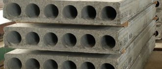
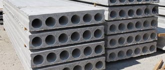
Calculation and design part
It is required to design a prefabricated hollow-core floor slab with the following data:
- slab width 1500mm;
- span of the slab in the axes is 5.9 m;
- standard payload on the overlap 1.5 kPa;
-environment class according to operating conditions – XC1;
- level of responsibility of the building –
II;
- slabs are manufactured using aggregate-flow technology;
- heavy concrete of compressive strength class C 25/30, subjected to heat treatment at atmospheric pressure;
— grade of concrete mixture for workability P1;
— working fittings class S800;
Design characteristics of materials
The working type is S800 class rod reinforcement tensioned by stops; The panel shelves are reinforced with welded wire mesh of S500 class. The concrete panels are accepted class C 25/30. The average relative air humidity is accepted at least 60%. Responsibility safety factor γ n
=0.95. Environment class according to operating conditionsХС1. Grade of concrete mix for workability P1. The concrete is subjected to heat treatment.
Characteristics of concrete
C 25 / 30 :
– guaranteed concrete strength
– standard resistance of concrete to axial compression
– average strength of concrete axial compression
– average strength of concrete in axial tension
– modulus of elasticity of concrete
– design resistance of concrete to axial compression
where c
– safety factor for concrete, adopted according to clause 6.1.2.11[1]:
1.5 – for reinforced concrete and prestressed structures;
– design resistance of concrete to axial tension
– average strength of concrete in axial tension
Characteristics
of prestressed reinforcement class S 800:
– standard resistance
– calculated resistance of prestressed reinforcement t.s. 6.2.2.3 [1]will be
where s
– safety factor for reinforcement, adopted according to clause 6.2.2.3 [1]:
1.25 – for prestressed reinforcement class S800;
– modulus of elasticity of rod reinforcement
Characteristics of non-prestressed reinforcement class
S 500:
– standard resistance
– calculated resistance for the wire
– calculated resistance of transverse reinforcement (welded frame)
Here s
1= 0.8 – coefficient of operating conditions for transverse reinforcement, takes into account the uneven distribution of stresses along the length of the rod;
s
2= 0.9 – the same, takes into account the possibility of brittle fracture of the welded joint. Accepted according to clause 6.2.1.3 [1]
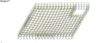
Load Definition
The composition of the floor is shown in Fig. 2.1.
Fig. 3.1 Floor composition
The definition of loads per 1 m2 of flooring is given in Table 3.1
Table 3.1 Loads per 1 m2 of floor
| Load name | Standard value, kN/m2 | γn _ | Design value γF =1, kN/m2 | γ F | Design value γF >1, kN/m2 |
| Constant load | |||||
| Linoleum, t = 4mm, ρ = 1500 kg/m3 | 0,06 | 0,95 | 0,057 | 1,35 | 0,077 |
| A layer of adhesive mastic, | 0,012 | 0,95 | 0,011 | 1,35 | 0,015 |
| t = 1mm, ρ = 1200 kg/m3 | |||||
| Cement-sand screed M200, t = 50mm, ρ = 1800 kg/m3 | 0,9 | 0,95 | 0,855 | 1,35 | 1,154 |
| Expanded polystyrene, t = 25mm, ρ = 30 kg/m3 | 0,0075 | 0,95 | 0,007 | 1,35 | 0,010 |
| Reinforced concrete hollow-core floor slab | 2,75 | 0,95 | 2,613 | 1,35 | 3,527 |
| Total | 3,730 | 3,543 | 4,783 | ||
| Variable load | |||||
| Payload | 1,5 | 0,95 | 1,425 | 1,5 | 2,138 |
| Total | 1,5 | 1,425 | 2,138 |
With a nominal panel width of 1.5 m, linear loads (at 1 m of length will be, N/m:
g
=
g d
1·1.5= 4.783·1.5= 7.175 kN/m – design constant;
q
=
q d
1·1.5= 2.138·1.5 = 3.207 kN/m – design variable.
When calculating the slab for the limit states of the first group, we compile the following combinations of loads:
– first basic combination
– second main combination
For further calculations we take the first
combination as the most unfavorable.
With a nominal panel width of 1.5 m, linear loads (at 1 m of length will be, N/m:
g
=
g d
1·1.5= 3.543·1.5 = 5.315 kN/m – design constant;
q
=
q d
1·1.5= 1.425·1.5 = 2.138 kN/m – design variable.
When calculating the slab for the limit states of the second group, we compose the following combinations of loads:
– normative (rare) combination
–frequent combination
– almost constant combination
Source: https://StudFiles.net/preview/4300412/
Programs for architects
Professional work on the design of buildings and structures is impossible without the use of technical programs for calculating floors. If building houses is your main occupation, it is worth making the effort to learn design tools.
ArchiCad program interface for floor calculations
The most common technical engineering programs in design organizations are ArchiCad, AutoCad, Lira, NormCAD and SCAD.
Advantages of engineering design programs:
- Versatility. Any of the programs can be used to construct and calculate all types of floors.
- Accuracy. The calculation takes into account a large number of factors that can affect the load and strength of the structure. Such detail in calculations allows you to obtain the most accurate data.
- Visualization. Having received the result, the builder clearly sees what and how he must install in order to obtain a guaranteed result.
- Preparation of project documentation. For professional developers, with the help of engineering programs, it is possible to prepare documentation that is accepted by all inspection bodies.
Disadvantages of engineering design programs:
- The claim that such tools are easy to learn is false. Often, their use requires special technical education, knowledge of strength materials and unified building codes.
- Volume of information: to work with engineering programs, you need to have a large amount of data, otherwise you can get unexpected calculation results.
- Access restriction: the programs are licensed; to use, you must purchase rights to use.
Calculation algorithm based on soil bearing capacity
When the dimensions of the foundation slab are determined, it is possible to calculate this structure based on the bearing capacity of the soil. The purpose of this operation is to assess the condition of the soil and its ability to withstand the total weight of all floor walls and other elements inside the building.
Example: Strong pressure on the soil will lead to excessive settlement of the foundation slab and displacement of soil layers. All this together will cause catastrophic consequences.
The foundation area is considered reliable if it exceeds the following condition:
in which S is the base of the house in sq. cm;
Kn – coefficient determining the reliability of the support (assumed equal to 1.2);
F – total mass of all floor slabs (including operational loads) on the foundation in kg;
Kр – coefficient that determines the working conditions;
R – conditional value of the calculated soil resistance in kg/sq.cm.
Reinforcement of a monolithic base
Working conditions on each soil take on different values. The type of building being constructed also affects the coefficient Kp. For example, it is necessary to build a heavy house on soil whose base is plastic clay. Kp in this case will be equal to 1. Light clay and fine sandy soils - Kp is equal to 1.2. Light construction on coarse sandy soil determines the Kp value to be 1.4. These coefficient values that determine construction conditions can be taken from special tables. The found figure is substituted into the above calculation.
Table 2. Values of coefficients that determine working conditions during the construction of a foundation on soils with organic components