Every building owner wants his structure to be reliable, functional, and not subject to destruction not just for years, but for decades. This is a completely natural desire for every person, regardless of what is in his property - a modest country house with a small plot or several huge production buildings of a factory enterprise. In order to fulfill his desire and keep the building in order, its owner regularly checks its condition and carries out the necessary repairs. It is especially important to remember that the condition of a building depends not only on its parts, but also on the site on which it stands. Therefore, building owners know that to take care of their property, installing surface drainage is essential.
Our Company offers you its services for the installation of surface drainage.
Installation of plastic trays.
Installation diagram of plastic trays.
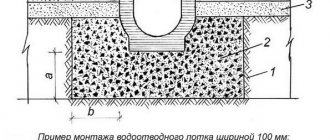
Scheme of joining trays with a sand trap and sewer pipes.
Plastic trays are installed in stages in the following order:
A trench is prepared in accordance with the diagram in the place where the tray will be installed;
-a concrete footing is made by laying concrete in even layers along the bottom of the trench; -plastic trays are located in the trench in the center; - the slopes are concreted to give the system stability.
Plastic drainage trays are connected to each other using the butt method. To do this, there is a tongue on one side of the tray and a groove on the other. To significantly increase the warranty period of plastic trays, the joints are sealed.
To attach the grid to the plastic tray, you must:
Install the main fastening system into the tray by unscrewing the bolt from it; - insert the bolt into the hole located on the grille; - firmly secure the bolt until it stops, checking the reliability of installation; - the stamped grille is attached very easily: the locks located at the edges of the grille are bent, the grille is fixed into the tray.
To make a side connection, you need to make a small hole in the side wall of the tray, connect the trays at right angles, seal and cap.
The advantages of plastic trays are much greater than their disadvantages.
The main advantages are: throughput. Smooth walls are not covered with growths, to which debris can cling and accumulate over time; durability, which is caused by resistance to loads, chemicals, temperature changes; light weight, which facilitates transportation and installation of such a system; several holes, which makes it possible to vary when connecting to a sewer pipe; installation is so primitive that one person can handle it without special education or specific or expensive equipment; Wide area of application - from intensive areas with a large number of pedestrians to small courtyard areas.
The disadvantages of plastic trays are: unreliability at temperatures below zero. Plastic may burst in severe frost or due to the weight of passing traffic; possible deformations over time due to different expansion coefficients of plastic and concrete. In addition, the plastic tray may fall out of the concrete trench over time; Due to the lightness of plastic, it must be pressed when connecting to concrete, which requires additional effort.
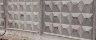
Installation of concrete trays.
Scheme of installing a concrete tray in asphalt.
Scheme of installing a concrete tray in concrete.
Scheme of installing a concrete tray in a tile.
Concrete trays are installed in a ditch on a concrete base in asphalt, concrete or tiles.
The thickness of concrete depends on the load class. The base, as a rule, is made of B25 concrete. The sides are fastened in the form of slopes. The width of the slopes also depends on the load class.
The correct deepening of concrete trays is checked as follows: after installation is completed, the extreme point on the grid should be 4 mm below the point of the road. Concrete trays are connected to each other and sealed. If the drain is connected
Installation of concrete trays.
Scheme of installing a concrete tray in asphalt.
Scheme of installing a concrete tray in concrete.
Scheme of installing a concrete tray in a tile.
Concrete trays are installed in a ditch on a concrete base in asphalt, concrete or tiles. The thickness of concrete depends on the load class. The base is usually made of B25 concrete. The sides are fastened in the form of slopes. The width of the slopes also depends on the load class.
at an angle, the concrete tray and lattice are sawn.
When installing concrete trays, one must not forget about expansion joints. The connection of concrete trays is carried out through a sand trap using a 100-160mm pipe or using a vertical pipe installed at the bottom of the tray.
The advantages of concrete trays are obvious - reliability and simplicity, special wear resistance. It should be noted that the scope of application of concrete trays is especially effective in Russia due to its special climatic conditions.
The correct deepening of concrete trays is checked as follows: after installation is completed, the extreme point on the grid should be 4 mm below the point of the road. Concrete trays are connected to each other and sealed. If the drainage is connected at an angle, the concrete tray and grate are sawed.
Concrete trays can withstand severe temperature overloads and retain their functionality. In addition, many concrete gutters and trays are resistant to various mechanical loads. Modern concrete trays are made using a special vibration pressing method; metal inserts are added to improve the class of the product and increase its wear resistance. Some products are made from fiber-reinforced concrete, concrete combined with fiberglass, the characteristics of which include increased impact resistance. An important factor in concrete trays is their correct installation and proper scope of application. Thus, there are general-purpose concrete trays, class C, with a cross-section of 100, and a load of up to twenty tons. For the movement of freight transport, more powerful drainage is required; super-class concrete trays are made for it for maximum load.
The only drawback of the average concrete tray is its low impact strength; this characteristic is especially important during transportation. As mentioned above, for a special type of work, especially strong concrete is made, trays from which are used on runways and in industry. Thus, when installing a concrete tray, you need the help of a specialist who will help you understand the class of concrete required for a specific drainage and install it correctly.
Drainage, as its name implies, ensures the removal of excess precipitation from the territory. While drainage systems save them from excess groundwater that harms the foundations of buildings, surface drainage saves the area from the occurrence of puddles and dirt, which harm the condition of the territory, make it difficult to move around it, and can also become dangerous, turning into ice in cold weather. of the year. Installation of surface drainage solves all these possible problems.
You should only trust such careful work as drainage installation to professional specialists. By contacting a professional company, you can be sure that all work will be carried out in compliance with all sanitary, hygienic, construction and safety standards.
Professionals will tell you in detail about each stage of work, its role in the drainage system, help you select the appropriate equipment, provide and agree on an installation plan. Our company guarantees you exactly this approach to work.
Our employees have significant experience working with such equipment, so we ensure that our customers complete their orders in the shortest possible time. In addition, the opportunity to work with one company from the moment of selecting and purchasing equipment to installing drainage systems will allow you to save money, since we value our customers and offer them the best prices.
The drainage systems installed by our company are always of high quality and reliable, because we work exclusively with proven equipment from the best suppliers. You can be confident that you have received certified equipment that meets all modern technical standards.
We carry out installation work within Moscow and the Moscow region. However, we always strive to meet our clients halfway, so it is possible for specialists to travel to regions close to the Moscow region.
For the drainage system to operate effectively, it is important to comply with all stages of its installation, in particular, the professional installation of drainage trays that collect and directed excess liquid to a specific location. Installation of drainage trays, which are special geometric structures shaped like a rectangle, square or oval, requires care and skill. Such work should only be trusted to experienced specialists.
The preliminary selection of the trays themselves is also important. Do you need trays made of concrete, or are plastic ones suitable? Is it possible to install open trays on your site or is it important to have a special grid? What depth and shape of trays best suit your conditions? Professional consultants from our company will give you answers to all these questions. You will definitely select the optimal equipment, and we, in turn, guarantee you professional installation of drainage trays. The combination of these two factors will allow you to get an excellent result, and the installation of drainage trays will be effective and efficient.
Drainage systems, the installation of which was carried out with high quality, will be effectively used for many years and will not create the slightest problems for the owners of the areas where they are installed. Provide yourself with the best equipment - contact professionals who have proven their effectiveness for installation work, contact our Company!
Drainage trays - plastic, concrete or cast iron - are used in the construction of surface-type drainage systems. Moreover, in such systems the tray “works” as a drainage channel that collects wastewater. Therefore, it is mounted near the road curb, under the sewer pipe, and at the end of the annular blind area.
And in this article we will look at typical types of trays, supplementing the overview of the product range with recommendations for the use of such catch basins in linear drainage systems.
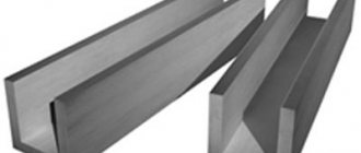
A typical tray is designed in the form of a cast U-shaped channel, the open edge of which is covered with a cast-iron grate.
Moreover, according to the European standard EN 1433, there are at least four types of such water conduits:
- The waste chute is made in the form of a straight gutter that receives water along its entire length (version I is mounted without lining and foundation, version M is mounted on a bedding and is equipped with its own foundation).
- Box-shaped tray - a U-shaped chute, the upper part of which is covered with a removable grid. This element protects the channel of the tray from large objects washed into the gutter by wastewater.
- A slotted tray is a square beam with a round through hole along the central axis, in the upper part of which a slot is cut, allowing access to the drain. Moreover, the gap can be longitudinal continuous or discontinuous. Such a tray can replace a box-shaped analogue with a grid.
- A curb tray is a slotted gutter with an L-shaped protrusion in the upper part that “covers” the gap in the tray body.
Such trays can be mounted not only under gutters, but also near the borders of garden paths. Well, the most durable products can be installed at airports, on highways and in heavy vehicle parking lots.
Range of drainage trays
Methods for manufacturing concrete trays involve the use of a limited set of initially plastic or thermoplastic structural materials during the production of such gutters. Therefore, storm gutters are made from thermoplastic polymers, cast iron and concrete.
This choice is explained by the use of foundry technologies (concrete and cast iron) or thermoplastic extrusion (plastic) in the production process. As a result, the manufacturer produces trays with different strength and performance characteristics.
That is why the classification of the range of trays, in most cases, is associated with the type of construction material used in the manufacture of such a product. And further in the text we will consider the assortments of polymer, cast iron and concrete trays.
Polymer trays
Structural polymer trays are made from mineral-filled polypropylene. This type of composite materials is highly resistant (they are almost impossible to scratch, and they are also inert to most chemicals) and no less noticeable strength (withstands loads of up to 60 tons/m2). And the operating temperature range of such material ranges from -50 to 120 degrees Celsius.
Therefore, such trays can be laid both near the house and near the railway track. Moreover, the weight of one module is only 9-14 kilograms.
Dimensions of a typical polymer tray:
- Length – one meter.
- Width – from 0.14 to 0.5 meters.
- Height – from 0.06 to 0.79 meters.
- The nominal diameter is from 0.1 meters.
Concrete drainage trays with grating
Concrete trays are made from compounds reinforced with fiberglass, polymer threads (polymer concrete) and steel wire (reinforced concrete). Moreover, in the process of manufacturing such products, vibration casting technology is used (a mold with a mass that has not yet hardened is immersed on a vibration stand).
As a result, concrete trays are characterized by high strength, which is unusual for standard reinforced concrete products (reinforced concrete products). Therefore, from such gutters it is possible to assemble both a surface-type home drainage system and its industrial analogue installed on highways and local roads.
Main dimensions of concrete trays:
- Gutter length, which ranges from 500 to 4000 millimeters
- The width and height of the gutter can be changed from 140x150 millimeters to 430x880 millimeters.
- Dimensions of the passage opening, which cannot be less than the catch diameter DN 100.
Specific dimensions of concrete trays are regulated by industry standards and manufacturer specifications.
Cast iron drainage trays
For the manufacture of trays, two types of cast iron are used: with lamellar graphite grain (ISO 185) and with spherical graphite grain (EN1563). Moreover, from these types of cast iron they produce not only the “body” (profile) of the tray, but also its grate.
And, of course, due to the tendency of cast iron to corrosion, the finished tray (and sometimes the grate) is subjected to hot-dip galvanizing (according to ISO 4161). However, a cast iron tray can be supplied to the consumer without a protective coating.
Due to their significant resistance to both longitudinal and lateral loads, cast iron gutters are installed only in critical areas (airports, heavy vehicle parking lots, etc.), where the installation of a cast iron drainage tray is justified from an economic point of view.
Main dimensions of cast iron gratings and trays:
- Maximum length – 500 millimeters
- The maximum width is 200 millimeters.
- The thickness of the grille is at least 50 millimeters.
- The through hole is at least DN100.
Concrete tray - the main types of tray products
Various types of trays are used in the construction and industrial sectors:
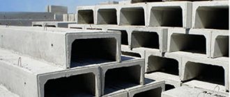
- U-shaped and rectangular profile products for the construction of prefabricated channels. Reinforced concrete cable trays are characterized by increased overall dimensions, allowing free placement of electrical communications for various purposes. The amount of free space inside the trays also allows them to be used to drain significant volumes of storm water. Prefabricated products have an increased margin of safety, as well as increased resistance to corrosion processes. This allows them to be used in soils with high humidity, as well as in the zone of soil freezing;
- trapezoidal telescopic trays of U-shaped configuration. Produced under production conditions, the products have precise overall dimensions. This greatly facilitates the pairing of trays during installation. Installation of telescopic trapezoidal trays is carried out in groups to ensure the required length of the line. The product is intended for installation along roadsides for accelerated drainage of precipitation. A distinctive feature of telescopic trays is their reduced water absorption, which significantly increases the duration of use of products of this type.
According to their functional purpose, design features and installation specifics, trays are divided into the following types:
- products for energy purposes, marked with the designation UBC or UBS;
- drainage and water disposal products marked MZhBL;
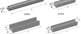
- tray channels for thermal routes and highways of type L;
- products for railway communications of the MPL or MSHL brand.
To seal concrete trays, special reinforced concrete slabs are used. The covering of cable trays is marked with the designation PT.
Reinforced concrete cable trays are used for laying electrical cables
Installation of drainage trays: basic rules
Installation of drainage trays is a very responsible operation. After all, the surface drainage system is located in a complex soil, which includes sandy loam and fertile soil. That is, you can’t count on high supporting ability.
In addition, such soil freezes 1-1.2 deep almost every winter. Therefore, heaving deformation will also act on the supporting surface of the tray, pushing the product out of the soil.
That is why when installing drainage trays you should be guided by the following set of rules:
- First, select a tray based on throughput capacity, based on the average monthly precipitation increased by 25 percent.
- Secondly, choose the optimal tray design and the material from which the product will be made, based on the location of the gutter. After all, a curb tray is not suitable for an airfield (based on its strength characteristics). In turn, the airfield tray will not fit into the home stormwater system (based on economic considerations).
- Thirdly, the minimum slope of a linear meter of the tray is 10 millimeters.
- Fourthly, do not skimp on the substrate - mount the tray on at least a 10-centimeter sand and gravel backing, or better yet, on a 10-centimeter gravel backing. Such a “cushion” will improve the strength characteristics of the soil and partially neutralize heaving deformation.
- Fifthly, stainless steel grates are easier to install (they weigh less than the cast iron version). In addition, they will last longer than their counterparts made of gray or ductile iron.
- Sixthly, the system must have a sand trap - the only protection of the drainage system from silting.
- Seventh, the grille must be secured using a special mechanism with a screw lock.
First, select a tray based on throughput capacity, based on the average monthly precipitation increased by 25 percent.
First, select a tray based on throughput capacity, based on the average monthly precipitation increased by 25 percent.
The process of assembling a drainage system based on drainage trays is implemented as follows:
- Along the curb or in another place chosen by the designer, the center line of the future drainage system is marked. To do this, just use pegs and twine.
- After this, meteorological observation data is requested, and based on this information, the average daily volume of runoff is determined, according to which the throughput diameter of the gutter is selected.
- The model and external dimensions of the water pipeline are determined by the flow diameter.
- Based on these dimensions, increased by 30-40 centimeters, the volume of soil excavation (trench dimensions) is determined. Moreover, the depth of the trench will be 10-15 centimeters below the height of the tray. After all, its edge, after installation, should be located below the zero level by at least 5 millimeters.
- At the next stage, a trench is dug, the selected soil is disposed of and a bedding is formed, with the help of which the slope is outlined and the bottom of the “pit” is strengthened.
- Next, drainage trays and sand traps are placed in the trench. Moreover, the outer catcher is connected with a DN100 pipe to the main (deep) drainage system.
- After this, concrete is poured into the space between the trench wall and the tray, fixing the drainage system in the selected location.
This drainage system is installed along the central paths on the site, laid between the gate and the entrance to the home. In addition, a ring water conduit is “circulated” around the blind area, which protects the soil from rain runoff. Moreover, a wall drainage system can be assembled from plastic, while a road drainage system can be assembled only from concrete blocks.
SECTION IV. AND METHODS OF LABOR WORKERS
Work prior to the construction of sewer wells is carried out by four specialized units: concrete workers, pipe layers, insulators and bulldozer operators.
The composition of units by profession and the work they perform are shown in the table.
| No. of links | Team composition by profession | Qty | List of works |
| 1 | Concrete worker - 4 rubles. Concrete worker - 2 rubles. | 1 1 | Installation of concrete preparation and trays Plastering of trays Installation of concrete blind area. |
| 2 | Pipelayers 4 r. | 2 | Completion of the pit manually. Checking the elevation of the pit bottom and the steepness of the slopes. Construction of foundations for wells. Installation of well and neck elements with sealing of seams and grouting of the surface with cement mortar. Well test. Soil compaction when filling a well. |
| Pipelayers 3 r. | 2 | ||
| Pipelayers 1 r. | 1 | ||
| Truck crane operator 5 r. | 1 | ||
| 3 | Insulator 3 r. | 1 | Heating bitumen in a mobile boiler. Cleaning and painting the inner surface of the rings with bitumen. |
| Insulator 2 r. | 1 | ||
| 4 | Bulldozer driver 5 r. | 1 | Backfilling the well pit with soil. |
| TOTAL: | 11 people |
The placement of equipment, devices and tools in the work area during the installation of wells is shown in the work flow diagram.
SEQUENCE OF WORK EXECUTION
| No. pp. | Process name | Sequence of work operations |
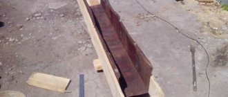
| 1. | Well construction. | Cleaning slopes and pit bottom. Mixing the soil at the base of the well with bitumen or tar materials. Soil compaction. Concrete preparation device for a well made of M-50 concrete. Installation of reinforcing mesh. Construction of a concrete tray M-100. Insulation on the edge of the pit with hot bitumen of the inner surface of the rings. Installation of well and neck elements. Grouting of joints with ironing and coating with hot bitumen. |
| 2. | Well test | Preliminary test of the well with water (before backfilling the pit). Elimination of defects. Final testing of wells (after backfilling the pit). |
| 3. | Backfilling of pits and trenches. | Filling well pits with soil (after testing the wells). Compacting soil with pneumatic rammers. Construction of a concrete blind area around the well neck. |
Features of drainage trays
Design and purpose
Drainage trays have a simple design. The product is a part in the form of a rectangular linear beam in which a gutter is made. If the tray is made of plastic, then it is U-shaped.
The purpose of a drainage tray can be understood from its name: collecting and draining water from the surface of paths, platforms, blind areas and other waterproof coatings. This is an important element of the site system.
A tray is a device that will help keep the area clean and well-groomed. Additionally, draining water around your home extends the life of your foundation.
A well-designed and constructed storm drain is essential if you want a site with beautiful landscaping and healthy plants, without puddles on the paths or dirt in the garden.
Types of trays
Drainage systems are used very widely, so there are a variety of trays for draining water. Concrete products are most often used.
But modern industry produces gutters from a variety of materials:
Disadvantages - heavy weight and more complex installation, fouling of the gutter with algae, silt and sediment.
Disadvantage: low strength and poor adhesion to concrete.
The disadvantage is high corrosion activity, so it is better to choose galvanized cast iron.
Trays for draining sediments may differ in such parameters as the maximum permissible load. Depending on this indicator, products are divided into classes:
- A15. Gutters of this class can withstand 1.5 tons of load and are used in local areas, sports fields, parks and pedestrian paths;
- B125. This class can withstand 12.5 tons and is used on roads for passenger cars, parking lots, and garage complexes;
- C250. Trays of this class can withstand 25 tons of load. They are used in parking lots, gas stations, car washes and other car service facilities;
- D400. These gutters can withstand 40 tons of maximum load. Their scope of application is wide: high-traffic highways, freight transport terminals, small enterprises, industrial zones;
- E 600. The products can withstand a load of 60 tons. They are used at piers, warehouses, large industrial facilities, road junctions and logistics centers;
- F900. This is the most durable class, capable of supporting up to 90 tons. Such trays are installed at airfields, military bases, heavy equipment parking lots, and at large mining enterprises.
For drainage of suburban areas, trays of classes A15 and B125 are used. The first are installed in a pedestrian area, the second - in places where a car can pass.
Installation of water drainage trays
Tool
It is quite possible to do the installation of drainage trays yourself. To do this you will need desire, technical savvy and a set of tools.
The most common tool needed:
- shovel,
- Bulgarian,
- level,
- thread,
- marker,
- rubber hammer,
- Master OK,
- basin for solution,
- construction knife,
- chisel,
- an ordinary hammer.
In addition, the technology requires the presence of a drawing or diagram according to which the trays will be installed. If you don’t have a professional document, draw the installation diagram “by hand” so that you don’t confuse anything during the work.
Step-by-step installation
The drainage system includes trays and a sand trap. The latter is installed at the lowest point. From it water flows into.
There is a special basket inside the sand catcher where settling debris and sand accumulate. Don't forget to clean it!
Instructions for installing concrete trays:
Reinforced concrete cable trays - product advantages
Concrete cable trays can significantly reduce the estimated cost of laying various communications by reducing the duration of laying highways, as well as significantly reducing the labor intensity of the work. From an economic point of view, the use of tray products provides a significant effect. Compared to performing an increased volume of excavation work associated with the need to lay power supply systems and various highways in the ground, installation of trays is less expensive.
Main advantages of the product:
- reliable protection of electrical cables and pipes from the influence of groundwater;
- preventing damage to highways as a result of soil pressure;
- the ability to install trays in wet soils;
- placement of utility networks in trays at the soil freezing level;
- safe location of communications in difficult terrain;
- the possibility of using electrical cables with reduced moisture protection;
- easier access to communications in case of need for repairs and maintenance;
- possibility of placing separating metal structures and special partitions inside the tray.
One of the advantages of trays is ease of installation. To install products in the soil, a trench is made into which U-shaped channels are laid. Coating waterproofing is mandatory when joining cable channels. After placing communications in the channel, the joint areas are treated with sealing mastic, a cover is installed and soil is backfilled.
All reinforced concrete trays, and heating main trays in particular, must have sufficiently high thermal and waterproofing to ensure protection of heating main pipes from environmental aggression
Professional builders are convinced of the following advantages of the product:
- increased strength properties;
- ability to perceive temperature fluctuations;
- Possibility of operation in conditions of high humidity;
- reliability and long service life;
- Possibility of use in aggressive environments;
- tightness of the box-shaped structure;
- practicality and maintainability.
If it is necessary to carry out activities related to the maintenance of communications and scheduled inspections, the soil should be removed to the level of the cover, the concrete tray ceiling should be dismantled, and damaged pipes should be replaced.
After completing the repair work and applying mastic to the mating surfaces, a cover is installed and soil is filled. Reinforced concrete channels are not dismantled and can be used for decades.
Conclusion
We looked at drainage trays, their features, types and installation rules. Now installing the gutter yourself should not cause you any difficulties. To consolidate your knowledge, watch the video in this article. And ask questions in the comments.
Before installing drainage trays, it is necessary to determine which objects and places most need protection from melt and rain water. These can be sidewalks, roads, buildings or entire areas. Considering that all the moisture accumulates in the lowlands, the main drainage system is first organized there and connected to the general drainage. Subsequently, it is there that the lines and slopes of drains are directed from the perimeter of the site, housing construction, paths, and on the scale of settlements from streets, sidewalks, squares and park areas.
Installation of drainage trays begins with an assessment of their strength and load-carrying capacity, depending on the location of their installation:
- on runways they use F900 tray blocks - with a lifting capacity of up to 90 tons;
- on areas and roads related to warehouses, logistics centers, industrial enterprises, with lifting capacity E600 - up to 60 tons;
- on transport highways, automobile enterprises and industrial zones, where the movement of all types of automotive equipment is provided, D400 is used - up to 40 tons;
- near workshops, services, car washes, gas stations serving all types of transport, they lay C250 - up to 25 tons;
- in areas where there is traffic for passenger cars, including garages, garden plots and parking lots, use B125 - up to 12.5 tons;
- under garden paths, pedestrian crossings, sports grounds, bicycle paths, it is recommended to install A15 - up to 1.5 tons.
Step-by-step installation technology:
- Marking and digging a trench along the external dimensions of the trays, taking into account the slope towards drainage, the height of the concrete pad is at least 100 mm. and deepening the grate under the level of asphalt or cement-sand coating at least 4 mm. For low-strength polymer products, it is necessary to fill walls with a thickness of at least 90 mm.
- Preparing the solution and laying the pillow
- At the beginning, a sand trap is installed on the damp concrete pad, and at the end, a pipe is installed to interface with the drainage system so that an optimal slope for drainage is provided, then a string is pulled between them.
- At the level of the string, blocks are laid on the raw mortar, simultaneously sealing the joints.
- After the concrete has completely dried, the side cavities are filled with appropriate material. In particular, the sidewalls of low-strength polymer products are filled with a solution.
- In the direction of the drainage line, special expansion joints are created using notches at a distance of 20 mm from each other, in order to avoid deformation of the tray system due to seasonal temperature changes.
- At the final stage, gratings are installed.
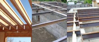
- In places where it is planned to organize a road surface, metal sheets are laid on the grid, the thickness of which is selected taking into account the expected load.
Further operation of the complex for collecting and draining melt and storm water comes down to periodic cleaning of the sand trap and ditch up to the connection with the drainage pipe.
Drainage trays are simple parts designed to create an open rainwater drainage system. Recently, the use of plastic trays has become widespread, as they are much more convenient than concrete ones. Let's look at how to select parts for a rainwater drainage system and install drainage trays.
An open rainwater drainage system copes with the assigned tasks quite effectively; its construction requires minimal expenditure of finance and labor.
The system has been in service for many decades, and its maintenance is extremely simple. The main element is a tray, closed on top with a protective grille to prevent debris from entering. You can assemble the system using concrete trays, but recently plastic trays have become much more popular.
Self-installation
Installing a drainage system with your own hands is not as difficult as it might seem. The most crucial moment is the calculation of all values and the selection of products with the required parameters, and their installation is relatively easy.
The preparatory stage looks like this: creating a project and diagram, taking measurements, calculations, selecting trays taking into account the design load and soil properties, determining the laying depth and ultimate capacity.
Preparing the trench
Often concrete channels are laid under drains in the form of a concrete layer at the bottom of the pit and side supports. The channels are made with a slope to ensure self-drainage of water. In this case, the length of the trench should be equal to the length of the entire system, the width should be 20 centimeters greater than the width of the drain. The depth is made equal to the height of the gutter with the grate plus a concrete layer and a 5 millimeter distance to the surface.
The location of the trenches can be marked with cords. After the trenches are ready, they are covered with sand in a layer of 10-15 centimeters, then thoroughly compacted. Concrete mortar is poured on top of the sand in a layer 10 centimeters thick. Only after this can the trays be installed.
If the system is installed on heaving soils, it is advisable to strengthen the trench and the entire structure with steel wire or rods.
Laying trays
The trays are laid using a certain technology. Despite the fact that the process itself is quite simple, you should not ignore any of the stages.
Sequence of laying trays:
- Laying out drains along the channels, choosing the highest point of the trench.
- Installing the gutter on still fresh concrete so that the elements do not move under load. It is imperative to maintain a certain level of inclination during installation.
- When 2 trays are installed, you need to ensure that the joints are sealed with a strand of any soft polymer, then fill them with concrete mortar.
- A tray is installed in the center of the trench, and to make it easier to remove the remaining concrete, it is covered with a polyethylene film when finished.
- The concrete mixture is poured into the distance between the trays and the sides of the trench.
- All corners are also treated with sealant.
- If you plan to lay asphalt on top of the drainage system, it is advisable to cover the trenches with fiberboards.
- After the trays are installed, all side spaces are carefully filled with a mixture of sand and gravel and compacted thoroughly (you can also fill it with concrete instead of backfill).
- After everything is compacted (if concrete was poured, it should harden), the upper parts of the drains are covered with grates. If it is necessary to make corner joints, the gratings are carefully sawed with a saw with a diamond blade.
Concrete water drains are high-quality and durable products, thanks to which you can quickly and easily install an effective water drainage system, guaranteeing the comfort and safety of operation of the territory and the objects located on it.
What are the advantages?
Why, when comparing concrete and plastic trays for a storm drainage system, do most developers choose parts made from polymer materials? The fact is that plastic trays are much more convenient, because they are durable, lightweight and have an affordable price. It is especially beneficial to use such parts when constructing rainwater drainage systems in areas near private houses and summer cottages, since in this case there is no significant physical stress on the drainage system.
Advice! Plastic trays are equipped not only with a horizontal, but also with a side fastening system, so they can be used to easily rotate. In addition, if necessary, you can connect the tray to the sewer pipe. This may be necessary if a mixed storm sewer is being built, when part of the system is laid underground.
Advice! Plastic trays are equipped not only with a horizontal, but also with a side fastening system, so they can be used to easily rotate. In addition, if necessary, you can connect the tray to the sewer pipe. This may be necessary if a mixed storm sewer is being built, when part of the system is laid underground.
Unlike conventional concrete trays, plastic products have a perfectly smooth inner surface. Therefore, the storm flow moves freely without hydraulic resistance. In addition, the absence of roughness on the bottom and walls significantly reduces the risk of clogging the system with sand and silt.
However, the main advantage of plastic trays, which distinguishes them from their concrete counterparts, is their low weight, which greatly facilitates transportation, loading and unloading and installation. Plastic parts, unlike concrete ones, are easy to process; they can be very easily shortened or cut at the desired angle.
Kinds
Plastic trays for rainwater drainage come in several types. Let's look at what options there are.
Universal
These details fully live up to their name. They can be used in a wide variety of areas. The parts are easy to install; they are often chosen for organizing storm drainage for a summer house or a personal plot near a house. They can be used in cases where the depth of the elements of the drainage system is standard.
Advice! Since the trays are covered with durable bars on top, their use is safe, even if children often play in the area.
Advice! Since the trays are covered with durable bars on top, their use is safe, even if children often play in the area.
Deep
If a stormwater drainage system is being built in an area where precipitation is heavy, deep trays should be selected. These parts are capable of draining large volumes of water from the territory. If, under such conditions, parts with a shallower depth are installed, the drainage system will quickly fail due to silting.
Extra strong
The difference between these plastic products is the presence of additional stiffeners. It is recommended to use the following storm drainage elements:
- in car parks;
- on the territory of garages;
- on the roadway.
Advice! Since the installation of extra-strong trays is expected in public areas, the models are equipped with anti-vandal fastening of the gratings.
Advice! Since the installation of extra-strong trays is expected in public areas, the models are equipped with anti-vandal fastening of the gratings.
Wear-resistant
These are storm sewer elements that are designed for use in particularly difficult conditions. They are designed for increased loads and are highly durable, as they are additionally reinforced with steel plates. This type of trays can withstand pressure of several tens of tons and ensures rapid drainage of rainwater.
How to install?
To assemble an open storm drain system, in addition to the trays, you need to prepare:
- sand;
- sealant;
- concrete solution.
In addition, if mixed rainwater drainage is installed, it is recommended to include a sand trap in the system, this will ensure normal operation of the drainage system. This element is installed at the junction of open trays with sewer pipes.
Installation of trays
The work is carried out as follows:
- The territory is marked according to the developed project;
- Trenches are dug in the designated locations. Its depth depends on the height of the tray used. This element is installed so that its edges are 5 cm below the ground level. In addition, you need to make a “reserve” of depth for installing a sand or concrete base;
- for the system to work effectively, the channels must be laid with a slope, the slope value is 1 cm per linear meter;
- the bottom of the prepared trenches is processed using a manual tamper. Then a layer of sand 5 cm thick is poured. If the soil in the area is weak, then it is necessary to provide a concrete base. In order for the trays to last longer, it is recommended to completely concrete the trenches, that is, cover not only the bottom, but also the walls with concrete mortar;
- the elements of the drainage system are being installed, and care must be taken to ensure that the slope is maintained;
- individual elements are joined to each other using special latches. To make the system more reliable, it is recommended to treat the joints with a special adhesive-sealant. It is important to choose a product that is resistant to high humidity and low temperatures;
- Grates are installed on top of the installed elements of the drainage system.
SECTION III. ORGANIZATION AND TECHNOLOGY OF THE CONSTRUCTION PROCESS
1. Before starting work on constructing wells, the following must be done:
— make a breakdown of well construction sites;
— clear the area of forest, bushes, etc.
— demolish or move buildings and structures from the construction site;
— build temporary roads or exits from permanent roads to service construction.
2. Transportation of reinforced concrete well elements and other building materials (mortar, cement, reinforcement) to well construction sites is carried out by trucks with trailers from the supply bases of construction and installation organizations.
3. The construction of wells is carried out in the following sequence;
— development of a pit;
— cleaning the bottom of the pit, checking that the bottom marks and the steepness of the slopes comply with the design;
— treatment of the base for wells with tar or bitumen materials to a depth of at least 0.2 m with careful compaction;
— concrete preparation device;
— installation of a concrete tray, reinforced with horizontal reinforcing mesh, and sealing of the ends of the incoming and outgoing pipes;
— insulation of the inner surface of reinforced concrete rings with bitumen mastic;
— installation of prefabricated reinforced concrete well elements;
— grouting the seams between the well elements with cement mortar;
- cement plaster and iron tray;
— backfilling the well with soil with careful compaction and installation of a waterproof lock on the pipe entries;
— installation of a concrete blind area around the neck of the well 1.5 m wide;
— insulation of the joints of the reinforced concrete rings of the well with hot bitumen over a primer;
— well testing (after completion of construction of the sewer network section).
Due to the fact that pits for wells are being developed simultaneously with trenches, issues of excavation work are not considered in this technological map. In calculating the costs of constructing wells, only the amount of excavation work that is associated with widening the trenches in the places where the wells are installed is taken into account.
CONSTRUCTION OF WELLS
1. Preparation of the foundations for wells is carried out as earthworks are completed at the site.
2. A preparation of 100 mm thick M-50 concrete is laid on the base.
3. The reinforcement mesh of the tray base is laid on the concrete preparation, the incoming and outgoing pipelines are installed in the design position and a tray made of M-100 concrete is installed.
4. After the concrete tray has acquired the required strength, the prefabricated reinforced concrete elements of the well are installed using a truck crane.
5. For slinging the elements, a four-leg sling with a lifting capacity of 2.0 tons is used.
6. All elements of the well are installed on M-50 cement mortar.
7. The construction of a clay castle is carried out after sealing the pipelines in the walls of the well. The width of the clay castle is taken to be 300 mm, and the height is 600 mm greater than the outer diameter of the pipelines connected to the well.
Well test
Wells of free-flow pipelines with internal waterproofing are tested for density by determining water leakage.
Testing of wells can be carried out either together with pipelines or separately. Before filling wells and trenches with soil, a preliminary test is carried out, and after filling, a final test is carried out.
Wells are tested for density no earlier than 24 hours after they are filled with water. Hydraulic pressure in a well in a leak test is created by filling the well to the top with water.
Wells are considered to have passed the preliminary test if no visible water leaks are detected during inspection. The amount of leakage should be determined by the volume of water added to the well to the original level during the test time, which should last at least 30 minutes. In this case, a decrease in the water level in the well is allowed no more than 20 cm. The well is recognized as having passed the final density test if the leakage or inflow determined during the test is equal to 60 l/day or less than this value.
Backfilling of trenches and pits
After testing the wells and pipelines, the well pits and trenches are backfilled layer by layer with soil using a bulldozer. Soil compaction is carried out using pneumatic rammers.