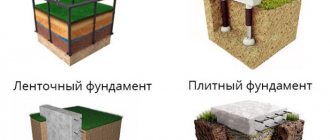
- Dense sand (coarse, medium, with gravel). An excellent foundation for building a house: the water drains quickly and the foundation is reliable. On such soils, you can build a house on a shallow foundation (laying depth from 50 cm).
Quick sands (fine and dusty). If the groundwater is deep, construction is possible. But these soils are dangerous because they float when saturated with water.
It is necessary to determine what kind of soils are in each layer
Difficulties often arise when trying to distinguish clay-containing soils. Sometimes it is enough just to look at them: if sand predominates and there are inclusions of clay, you have sandy loam in front of you. If clay predominates, but there is also sand, it is loam. Well, the clay does not contain any inclusions and is difficult to dig into.
There is another method that will help you make sure how correctly you have identified the soil. To do this, roll a roller from moistened soil with your hands (between your palms, like you used to do in kindergarten) and bend it into a donut. If everything has crumbled, it is low-plasticity loam; if it has fallen into pieces, it is plastic loam; if it remains intact, it is clay.
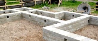
Having decided what kind of soil you have in the selected area, you can begin to choose the type of foundation.
Shallow strip foundation - calculation and design.
Shallow strip foundation according to SNIPs.
A shallow strip foundation (hereinafter referred to as MZLF) is one of the types of strip foundations, which is characterized by a shallow depth, significantly less than the depth of soil freezing, and a relatively small consumption of concrete mixture. This article discusses the main advantages and disadvantages of MZLF, the most common mistakes in their construction, a simplified calculation method suitable for private developers (not professionals), and recommendations for constructing a foundation with your own hands. The main advantages of MZLF are:
- economical - concrete consumption is significantly lower than during the construction of a conventional strip foundation. It is this factor that most often determines the choice of this technology in low-rise construction;
- reduced labor costs - less excavation work, less volume of prepared concrete (this is especially important when it is not possible to pour the finished mixture from a mixer);
- smaller tangential forces of frost heaving due to the reduced area of the lateral surface of the foundation.
However, during the construction of the MZLF, it is necessary to strictly adhere to the technology; a frivolous attitude to the process can lead to the appearance of cracks, and then all of the above advantages, as they say, will go down the drain.
The most common mistakes made when installing MZLF:
1) selection of the main working dimensions of the foundation without any (even the most simplified) calculation at all;
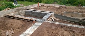
2) pouring the foundation directly into the ground without covering it with non-heaving material (sand). According to Fig. 1 (on the right), we can say that in the winter season the soil will freeze to the concrete and, rising, drag the tape upward, i.e. the tangential forces of frost heaving will act on the foundation. This is especially dangerous if the MZLF is not insulated and a high-quality blind area is not equipped;
Shallow strip foundation for a house according to SNIP.
3) improper reinforcement of the foundation - choosing the diameter of the reinforcement and the number of rods at your discretion;
4) Leaving the MZLF unloaded for the winter - it is recommended that the entire cycle of work (construction of the foundation, erection of walls, insulation of the foundation and arrangement of the blind area) be carried out one construction season before the onset of severe frosts.
Calculation of a shallow strip foundation.
The calculation of the MZLF, like any other foundation, is based, firstly, on the value of the load from the weight of the house itself and, secondly, on the calculated soil resistance. Those. the soil must withstand the weight of the house transmitted to it through the foundation. Please note that it is the soil that supports the weight of the house, and not the foundation, as some believe.
If an ordinary private developer can calculate the weight of a house if desired (for example, using our online calculator located here...), then it is not possible to determine the calculated soil resistance on your site on your own. This characteristic is calculated by specialized organizations in specialized laboratories after conducting geological and geodetic surveys. Everyone knows that this procedure is not free. Mostly, architects who design a house resort to it, and then, based on the data received, they calculate the foundation.
In this regard, it makes no sense to provide formulas for calculating the size of the MZLF within the framework of this article. We will consider the case when a developer carries out construction on his own, when he does not conduct geological and geodetic surveys and cannot accurately know the calculated soil resistance on his site. In such a situation, the dimensions and design of the MZLF can be selected according to the tables below.
The characteristics of the foundation are determined depending on the material of the walls and ceilings of the house and its number of storeys, as well as on the degree of heaving of the soil. How you can determine the latter is described here...
I. MZLF on medium and highly heaving soils.
Table 1: Heated buildings with walls made of lightweight brickwork or aerated concrete (foam concrete) and reinforced concrete floors.
Table 1. Shallow strip foundation according to SNIP.
— the number in brackets indicates the pillow material: 1 — medium-sized sand, 2 — coarse sand, 3 — a mixture of sand (40%) with crushed stone (60%);
— this table can also be used for houses with wooden floors, the safety margin will be even greater;
— see below for foundation design options and reinforcement options.
Table 2: Heated buildings with walls made of insulated wooden panels (frame houses), logs and timber with wooden floors.
Table 2. Shallow strip foundation according to SNIP.
— the numbers in brackets mean the same as in Table 1;
- above the line value for walls made of insulated wooden panels, below the line - for log and timber walls.
Table 3: Non-buried foundations of unheated log and timber buildings with wooden floors.
Table 3. Shallow strip foundation according to SNIP.
- above the line values for log walls, below the line - for walls made of timber.
Design options for MZLF on medium- and highly heaving soils, indicated in the tables by letters, are shown in the figures below:
Foundations on heaving soils according to SNIPs.
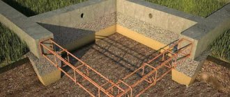
1 - monolithic reinforced concrete foundation; 2 - sand filling of sinuses; 3 - sand (sand-crushed stone) pillow; 4 - reinforcement frame; 5 - blind area; 6 - subfloor (shown conditionally); 7 - waterproofing; 8 - base; 9 — ground surface; 10 - sand bedding; 11 - turf.
Option a. — the upper plane of the foundation coincides with the surface of the earth, the base is made of brick.
Option b. - the foundation protrudes above the surface by 20-30 cm, forming a low base or being part of the base.
Option c. - the foundation rises 50-70 cm above the ground. At the same time, it also serves as a base.
Option d. - non-buried foundation-base; Table 3 shows that such foundations are used for unheated wooden buildings.
Option d. - used instead of option b. or in. . when the width of the base of the foundation significantly exceeds the thickness of the wall (more than 15-20 cm).
Option e. - a shallow strip foundation on a sand backfill is used quite rarely on weak (peaty, silted) soils with a high groundwater level for wooden buildings. Depending on the size of the building, bedding is done either under each strip or under the entire foundation at once.
Reinforcement of a shallow strip foundation.
MZLF reinforcement is made with meshes of working reinforcement and auxiliary reinforcing wire. The working reinforcement is located in the lower and upper parts of the foundation, and it must be immersed in the thickness of the concrete by about 5 cm. The lower mesh works to deflect the foundation tape downward, and the upper mesh works to deflect the tape upward. There is no point in placing the working reinforcement in the middle of the tape (as can sometimes be seen on the Internet).
Table 4: Options for foundation reinforcement.
Table 4. Options for reinforcing a shallow strip foundation according to SNIP.
MZFL reinforcement schemes are shown in the following figure:
Reinforcement scheme according to SNIP.
A. — a mesh with two working reinforcement rods; b. — a mesh with three working reinforcement rods; V. — T-shaped joint; g. - L-shaped corner joint; d. - additional reinforcement of MZLF with a large width of the sole, when the sole is more than 60 cm wider than the base (the additional mesh is located only in the lower part.
1 - working fittings (A-III); 2 — auxiliary reinforcing wire ∅ 4-5 mm (Вр-I); 3 - vertical reinforcement rods ∅ 10 mm (A-III), connecting the upper and lower mesh; 4 — reinforcement for strengthening the corner ∅ 10 mm (A-III); 5 - connection with wire twists (twisting length is at least 30 diameters of the working reinforcement); 6 — additional working fittings ∅ 10 mm (A-III).
II. MZLF on non-heaving and slightly heaving soils.
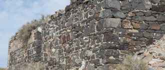
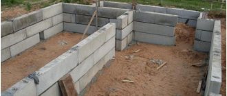
Shallow strip foundations on non-heaving and slightly heaving soils do not have to be made only from monolithic concrete. You can also use other local materials, for example, rubble stone, red ceramic brick. MZLF is laid at 0.3-0.4 meters without a sand cushion. Moreover, for wooden buildings and one-story brick (or aerated concrete) foundations, they don’t even need to be reinforced.
For 2- and 3-story houses with walls made of stone materials, MZLF is reinforced. Concrete foundations are reinforced according to the 1st reinforcement option (see Table 4 above). Foundations made of rubble or brick are reinforced with masonry mesh made from BP-I reinforcement ∅ 4-5 mm with a cell size of 100×100 mm. The nets are placed every 15-20 cm.
MZLF structures on non-heaving and slightly heaving soils are shown in the figure below:
Shallow strip foundation for a private cottage according to SNIPs.
1 - foundation; 2 - base; 3 - blind area; 4 - waterproofing; 5 - subfloor (shown conditionally); 6 - mesh made of wire reinforcement, 7 - reinforcement according to option 1 (see table 4)
Options a. and b. - for wooden and one-story brick (aerated concrete) buildings.
Options c. and g. - for two- and three-story brick (aerated concrete) buildings.
The width of the sole b is determined depending on the number of storeys of the building and the material of the walls and ceilings.
Table 5: Values of the width of the sole of the MZLF on non-heaving and slightly heaving soils.
Table 5. Width of a shallow strip foundation on heaving soils according to SNIP.
Stages of construction of a shallow strip foundation and recommendations.
1) Before starting construction of the foundation, if necessary, it is necessary to ensure high-quality drainage of surface rainwater from neighboring areas from the building site. This is done by cutting out drainage ditches.
2) The foundation is marked and trenches are torn out. It is recommended to begin excavation work only after all necessary materials have been delivered to the construction site. It is advisable to organize the process of cutting out the trench, filling the tape, backfilling the sinuses and constructing the blind area as a continuous process. The less it is extended in time, the better.
3) The dug trenches are covered with geotextiles. This is done so that the sand cushion and sand filling of the sinuses do not become silted over time by the surrounding soil. At the same time, geotextiles allow water to pass through freely and do not allow plant roots to grow.
4) A sand (sand-crushed stone) cushion is poured layer by layer (in layers of 10-15 cm) with careful compaction. They use either manual rammers or area vibrators. Tamping should not be taken lightly. Shallow foundations are not as powerful as foundations poured to the full depth of freezing, and therefore freezing here is fraught with the appearance of cracks.
5) The formwork is laid out and the reinforcement frame is knitted. Do not forget to immediately provide water and sewerage to the house. If the foundation is also a plinth, remember about the vents (does not apply to buildings with floors on the ground).
6) Concrete is poured. Filling of the entire tape must be done continuously, as they say, in one go.
7) After the concrete has set (3-5 days in summer), the formwork is removed and vertical waterproofing of the foundation is done.
The sinuses are backfilled with coarse sand with layer-by-layer compaction.
9) A blind area is being constructed. It is advisable (especially with a small height of the foundation tape) to make the blind area insulated. This measure will further reduce the forces of frost heaving affecting the MZLF in winter. Insulation is made with extruded polystyrene foam.
As already mentioned at the beginning of the article, it is not allowed to leave the MZLF unloaded or underloaded (the building is not fully built) for the winter. If this happens, the foundation itself and the soil around it must be covered with any heat-saving material. You can use sawdust, slag, expanded clay, straw, etc. There is also no need to clear the snow on the construction site.
It is highly not recommended to build a shallow strip foundation in frozen soil in the winter.
Load collection
The collection of loads is carried out by summing them of each type (permanent, long-term, short-term) and multiplying by the cargo area. In this case, load reliability factors are taken into account.
Values of reliability factors for load according to SP 20.13330.2011.
Standard values of payloads depending on the purpose of the room in accordance with SP 20.13330.2011.
Constant loads include the dead weight of structures. For long-term ones - the weight of non-load-bearing partitions (in relation to private construction). Short-term loads include furniture, people, and snow. Wind loads can be neglected unless we are talking about building a tall house with narrow plan dimensions. Dividing loads into permanent/temporary ones is necessary to work with combinations, which can be neglected for simple private buildings by summing all loads without reducing combination factors.
At its core, load collection is a series of arithmetic operations. The dimensions of the structures are multiplied by the volumetric weight (density) and the load safety factor. Uniformly distributed loads (payload, snow, weight of horizontal structures) form support reactions on underlying structures in proportion to the load area.
We will analyze the collection of loads using the example of a private house 10x10, one floor with an attic, walls made of D400 gas block 400 mm thick, symmetrical gable roof, ceiling made of prefabricated reinforced concrete slabs.
Diagram of cargo areas for load-bearing walls at the floor level of the first floor (in plan.
Diagram of cargo areas for load-bearing walls at the roof level (sectional view.
Collecting the snow load poses some difficulty. Even for a simple roof, according to SP 20.13330.2011, three loading options should be considered:
Scheme of snow loads on the roof.
Option 1 considers uniform snowfall, option 2 – asymmetrical, option 3 – the formation of a snow bag. To simplify the calculation and to form a certain reserve of bearing capacity of foundations (especially necessary for approximate calculations), you can take a maximum coefficient of 1.4 for the entire roof.
The end result for collecting loads on a strip foundation should be a linearly distributed (linear along the walls) load acting at the level of the base of the foundation on the ground.
Table for collecting uniformly distributed loads
| Load name | Standard value, kg/m2 | Load safety factor | Design load value, kg/m2 |
| Self-weight of floor slabs | 275 | 1,05 | 290 |
| Self-weight of the flooring | 100 | 1,2 | 120 |
| Self-weight of plasterboard partitions | 50 | 1,3 | 65 |
| Payload | 200 | 1,2 | 240 |
| Own weight of rafters and roofing | 150 | 1,1 | 165 |
| Snow load | 100*1.4 (bag) | 1,4 | 196 |
Total: 1076 kg/m2
The standard value of snow load depends on the region of construction. It can be determined according to Appendix “G” SP 20.13330.2011. The self-weights of the roof, rafters, flooring and partitions are taken as an approximate example. These values should be determined by direct calculation of the weight of a particular structure, or an approximate determination from reference literature (or in any search engine for the query “own weight xxx”, where xxx is the name of the material/structure).
Let's consider the wall along the "B" axis. The width of the cargo area is 5200mm, that is, 5.2m. Multiply 1076kg/m2*5.2m=5595kg/m.
But that's not the whole load. You need to add the own weight of the wall (above and underground parts), the base of the foundation (approximately its width can be taken as 60 cm) and the weight of the soil on the edges of the foundation.
For example, let’s take the height of the underground part of a concrete wall to be 1 m, thickness 0.4 m. Volumetric weight of unreinforced concrete is 2400 kg/m3, load safety factor is 1.1: 0.4m*2400kg/m3*1m*1.1=1056kg/m.
In the example, we will take the upper part of the wall to be 2.7 m made of aerated concrete D400 (400 kg/m3) of the same thickness: 0.4 m * 400 kg/m3 * 2.7 m * 1.1 = 475 kg/m.
The width of the sole is conventionally assumed to be 600mm, minus the wall of 400mm, we get overhangs totaling 200mm. The density of the backfill soil is taken to be 1650 kg/m3 with a coefficient of 1.15 (the height of the thickness will be determined as 1 m of the underground part of the wall minus the thickness of the first floor floor structure, let the total be 0.8 m): 0.2 m**1650 kg/m3*0, 8m*1.15=304kg/m.
It remains to determine the weight of the sole itself with its usual height (thickness) of 300 mm and the weight of reinforced concrete 2500 kg/m3: 0.3m*0.6m*2500kg/m3*1.1=495kg/m.
Let's sum up all these loads: 5595+1056+475+304+495=7925kg/m.
More detailed information about loads, coefficients and other subtleties is presented in SP 20.13330.2011.
Do-it-yourself shallow strip foundation from A to Z.
Shallow strip foundation for a private house according to SNIPs
Usually, when private buildings with a small number of floors are built from lighter materials (bricks, gas blocks, foam concrete, etc.), a strip foundation at a shallow depth is used. This solution is beneficial in terms of economy and practicality.
For such a foundation, a pit is created for a brick house or for a house made of aerated concrete. It goes deeper below the soil freezing mark. In the Urals and Siberia, and in other areas with severe cold, it deepens below 150 cm. And in such an area it is necessary to work with heavy equipment. This foundation covers the perimeter of all load-bearing walls. Its construction is only in exceptional cases lower than 150 cm. SNiP for this type of foundation is calculated from the load of the walls per area. The bearing capacity or characteristics of the soil in a particular area are also taken into account.
Advantages of this foundation:
- Ease of work.
- Good cost savings.
- There is no need to use special equipment (it is only needed in the specified regions).
- Excellent strength if a small building of 1-2 floors is being erected.
- Makes it possible to insulate semi-basement rooms.
- A wide range of materials and technological solutions for its construction.
- It can be created as a monolithic type, where concrete is poured.
- Its other configurations are bricks or concrete blocks.
The design of such a foundation:
Shallow strip foundation according to SNIP.
- Weak strength for buildings on heaving soils. The dilemma is solved thanks to sand filling and a drainage system. This reduces the impact of the soil.
- Impossibility of creation on frozen ground.
- It cannot be left unloaded during the winter.
- Points 2 and 3 determine the short time frame for pouring it and erecting walls: about 4-5 months.
Learn more about monolithic strip foundations and slabs.
There are several types or subtypes for MLF. Let's list everything:
- Ribbon belts. Without recesses, suitable for frame houses and light structures. The peculiarity is that the width is always greater than the height. This will make the supporting surface much better.
- Non-recessed tape. Ideal for wood structures. Feature: the base belt is raised.
- Shallow LF. Let's analyze its device more carefully. Can be used for any type of building, both log and stone.
- Recessed is, in fact, a monolithic slab, because it is poured below the freezing level. Suitable for absolutely any structure.
For your information! Any type or type of MLF cannot be put into operation without drainage, waterproofing and backfilling with sand.
Ways to reduce the depth of soil freezing
The rate of soil freezing can be reduced by insulating the foundation itself. The land outside the base is also cultivated. The procedure is performed using polystyrene foam plates. For hydrolysis, you need to wrap them in a membrane film. The amount of insulation is determined by the general climatic conditions of the region, the level of groundwater, the thickness of the foundation and other factors.
You can use other materials for insulation. The main thing is that they provide not only thermal insulation, but also the necessary strength. The thickness of the layer depends on the thickness of the insulation.
Stages of creating a strip foundation at shallow depths (LFMG).
When working on heaving soils, it is necessary to insulate the soles of the working tape of this foundation. In conditions of sand and sandy loam, it is fashionable to insulate only the blind area.
- Calculation of tape width and reinforcement section, creation of a reinforcement project.
- Creating a trench if a house without a basement is being built.
- A pit is dug if a base is planned.
- Laying drains to remove runoff.
- Warming of the sole.
- Creating a substructure.
- Installation of formwork.
- Laying of reinforcement.
- Pouring concrete. The organization of communications and ventilation ducts is provided.
- Waterproofing of all edges of the tape after dismantling the formwork.
- For a functioning basement, the outer walls are insulated with tape.
Determination of soil composition.
This procedure can be performed without specialists. Just dig holes in different places. Examine the soil visually. Here's how to do the test:
- It easily forms into a dense ball and does not collapse when pressed with your fingers. These are signs of clay.
- If it cracks under pressure, it is loam.
- If it has partially crumbled, it is sandy loam.
- It didn't turn out to be a ball at all - it was sand.
Calculation of tape width.
Here the total load is calculated. It includes the weight values of all structures:
- base;
- floors;
- walls;
- roof;
- facing;
- insulation materials;
- partitions;
- furniture;
- living people;
- loads from wind and snow.
Wind and snow data is obtained from the weather report for your area. Typically, a width of 40-50 cm is sufficient to create a strong tape even on difficult soils.
Calculation of depth.
Here are the rules:
- A depth of 40 cm is suitable if there is protection against heaving.
- 45 cm – subject to sandy soil; groundwater is low.
- 50 cm – when the clay freezes to 100 cm.
- 75 cm – clay freezes to 150 cm.
- 100 cm – freezing at 250 cm.
There are ways to protect against swelling in winter:
- Under the sole the soil is changed to non-metallic material. Minimum layer – 40 cm.
- Drainage is created around the perimeter.
- A blind area and storm drain are installed on the surface.
- The sole and blind areas are insulated.
Shallow strip foundation based on snips in section.
The following numbers will help in the question of how much the tape should be raised above the ground:
- for the base, the tape is buried in place and rises 170 cm above the surface;
- for a modest technical underground, a height of 40 cm above the ground will do;
- to create floors on the ground, the tape is at the same level with the ground or exceeds it by 20 cm.
Advice! Any of these options allows for normal two-layer reinforcement inside the tape. At the same time, you can still arrange a protective layer of 1.5 - 4 cm.
It is advisable to use a calculator when making calculations:
At the building site, you need to tighten the cords. They are located along the outer and inner perimeter. There is no need to remove the axes here, as when working on columnar or pile foundations.
Positional criteria for marks and cords.
- The starting angle of the main facade is positioned 3 m from the site line, 5 m from the axial border of the street.
- To mark the wall of the main facade, two cords are pulled over the cast-offs. A 60-80 cm strip is placed between the pegs. These cords also reflect the edges of the foundation.
- For each wall, a right angle is determined. After which the side walls are calculated. Here the work follows the triangle method. They also require pulling the cords over the cast-offs.
- The rear façade and interior walls are determined using the same method.
Next, pits are marked for the foundations of separate structures of the building: porch, pumping equipment, stairs, stove, etc.
A level is used to align the horizontal lines of all castoffs in a single plane. Correct positions of the cords: 5-7 cm below the top side of the formwork.
Also, the tape trenches must provide for the location of insulation, drainage, and access to the external walls of the tape. To do this, the width of the trench develops 50–80 cm inside the perimeter of the building, 80–120 cm outside.
For excavation work, you can only draw the contours of the trenches. This is done on the soil using lime mortar. If there is a base, a pit is dug out. The cast-offs in the corners should not interfere with the removal of soil, which is carried out by special equipment.
Substrate made of sand or crushed stone.
Typically the substrate is formed from:
- sand, layer 20 cm, it is treated with water or compacted with a vibrating plate;
- crushed stone, the same layer, it is manually bayoneted in layers or similarly compacted.
An example of a sand cushion.
Shallow strip foundation of the house according to SNIPs.
The crushed stone layer covers the sand layer.
Shallow strip foundation of a private house according to SNIPs.
At this stage, drainage is installed along the entire strip perimeter. They should be flush with her sole. The drains are looped into a single circuit. This results in one slope towards the underground compartment where wastewater will accumulate.
With a 40-centimeter immersion of the foundation, it is possible to get rid of heaving. To do this, line the outer side of the tape with polystyrene. Required layer – 5 cm. Width – 60 cm.
When the foundation is 70–100 cm deep, it is necessary to insulate the blind area. Insulation is carried out at a level of 30-40 cm. Heaving impulses are not completely eliminated, but are reduced significantly.
As a rule, the following materials are used to create shields:
- Edged board. The minimum thickness is 5 cm. Its advantages are that it can be reused. Disadvantage: assembly takes a lot of time.
- Plywood with many layers. Its advantages: powerful resistance to moisture, strength. The downside is the huge price.
- OSB. Pros: can be used after the formwork has been dismantled, strong moisture resistance, retains geometry.
For your information! Crossbars are placed at the level of the formwork, and the cast-offs are pulled out. This way the formwork is level, both horizontally and vertically.
It is important to know! In areas of connections in shields, gaps larger than 2 mm are not allowed. The concrete base is poured without formwork. Its functions are performed by the walls of the trench.
Formwork installation options:
- Removable. The top side of the boards exceeds the design mark by 5-7 cm. The walls inside are insulated with extruded polystyrene foam.
- Fixed. Polystyrene blocks are used for assembly. The rigidity of the structure is determined by the jumpers.
The first option is more popular, because after pouring, water protection is installed on the surface. Then insulation is laid on it.
Shallow strip foundation of the cottage according to SNIPs.
An example of placing and strengthening formwork:
Screeds are used for vertical fixation of panels. Required pitch: 50 – 100 cm. Holes are placed inside the ties at different heights. The cartridges will pass through them. And in the underground side, engineering technologies will be introduced through such pipes. Above ground level, the holes will become ventilation ducts. Through them, moisture will leave the underground.
Minimum depth depending on the type and depth of soil freezing
Laying the foundation to a certain depth is carried out taking into account many factors. We will also have to build on the minimum standards for deepening the foundation. The lowest indicators are determined by the level of soil freezing, the location of groundwater, and the porosity coefficient.
Minimum foundation depth according to SNiP:
- With a freezing depth of heaving soil of 1 m and non-heaving soil of 2 m, the foundation depth is 50 cm;
- With a freezing depth of 1.5 and 3 m for non-heaving and heaving soil, respectively - 75 cm;
- For large indicators, a minimum depth of 100 cm is used.
Greater freezing depth and close proximity of groundwater increase the load during seasonal heaving. That is why it will be necessary to equip the foundation deeper. But if you properly insulate the base and arrange a drainage system, then the depth indicator can be small.
Reinforcement and filling.
Foundations built on heaving soils experience impressive loads. For this reason, reinforcement is carried out at the edge of the tape at the top and near its sole. The rods are protected from corrosion. The thickness of the protective layer should reach at least 1.5 - 4 cm.
To reinforce the monolith, rods of 8-16 mm are used. This is a periodic longitudinal section. The reinforcement structure becomes more rigid if rectangular clamps are attached to it. They are formed from smooth reinforcement with a parameter of 6-8 mm.
One of the popular reinforcement schemes:
Shallow strip foundation of a private cottage according to SNIPs.
Independent calculation of reinforcement is based on the cross-section of the tape, taking into account 0.1% of the reinforcement from the total area. Calculation methods:
- The total cross section is calculated. The height of the tape (H) is multiplied by its width (W) and divided by 100 (calculation is in mm). Formula: H x W. 100.
- The cross-section of the longitudinal rod is determined from the reinforcement diagram sheet.
- The adjustment takes into account a 4 cm layer of protection, according to the criteria of SP 52.101. THAT is, the maximum number of rods in a row is 40.
- The thickness of the clamps should be a quarter less than the main rods.
Example of corner reinforcement:
Shallow strip foundation of the house according to SNIP.
Wire is used to tie the frame. It can be tied mechanically or manually.
Example of reinforcement of mating sections:
Shallow strip foundation of a private house according to SNIP.
Reinforcement criteria for this foundation:
- The overlap is spread in adjacent lines of one belt by at least 60 cm.
- The length of the overlap is equal to 50 rod diameters.
- In areas where walls meet and at corners, joints of rods are not allowed. One rod is bent there and ends up on the adjacent side by 40-60 cm. Then it is overlapped with the next part of the reinforcement.
Criteria for independently creating a concrete composition.
The elements of concrete mortar are classic: crushed stone, sand and cement. Each brand of cement has its own mixing proportions:
M 300: crushed stone - 3.7 shares, sand - 1.9 shares, cement - 1 share.
M 250: 3.9 (crushed stone), 2.1 (sand), 1 (cement).
M200: 4.8 (w), 2.8 (p), 1 (c).
M150: 5.7 (w), 3.5 (p), 1 (c).
M100: 7 (sch), 4.6 (sand), 1 (c).
Mixing should only be done in a concrete mixer. The time of this operation is 1.5 minutes. You can add various additives to improve the quality of the composition. Grade M100 should be used only for footings.
An example of laying engineering sleeves in formwork:
Shallow strip foundation of a cottage according to SNIP.
The filling criteria are:
- The composition is laid one vector at a time in layers. Each layer is 40-60 cm. It is compacted with a vibrating tool.
- The formwork is filled in one session.
- Allowable pauses are 2 hours, no more.
- The composition is poured from a height of 50 -200 cm above the formwork.
- The vibrating tool attachment is placed in the composition for 2-10 seconds. Air bubbles should disappear.
Concrete maintenance and formwork removal.
When the composition in the formwork has strengthened by 50-70%, maintenance of the concrete is necessary. Here you will need the following operations:
- It is covered with a film that creates protection from precipitation and excessive moisture.
- A heat cable is laid into it, a warm formwork or a layer of straw is installed. This protects the concrete from freezing. This is especially true in winter.
- The concrete is covered with a tarpaulin and watered from a watering can. There should be a diffuse stream. The operation is performed in the first three days after filling. This protects the concrete from active evaporation.
These actions help eliminate the appearance of cracks, shrinkage, and internal stresses. In hot weather, concrete should be moistened after 8 hours. Maintenance of constant compress conditions is required.
Removal of formwork can be done in accordance with air temperatures:
At +30, removal 4 days after pouring,
At +20 – after 8 days,
At +10 – after 14 days
At +5 – after 28 days.
After removing the formwork, waterproofing is installed on the sides of the foundation.
Shallow strip foundation of a private cottage according to SNIP.
Methods for waterproofing a monolith:
- Applying 2-3 layers of bitumen mastic.
- Pasting with roll polymers.
- Treatment with penetrating compounds.
The outer walls of the foundation should be insulated along their entire height. Bitumen mastic is used to attach the insulation. Then the blind area is insulated around the circumference of the foundation.
If there is high ground water in the area, drainage is created.
Example of a completed foundation:
Shallow strip foundation for a house according to SNIPs.
Manufacture and scope.
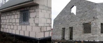
They use a shallow strip foundation for a house made of aerated concrete, for buildings made of wood, or for structures with a light load. At the same time, it has many advantages over a full-fledged type of base, since it allows you to save on material and physical labor during installation.
Scheme of a shallow foundation for a house made of aerated concrete.
The manufacturing principle of all strip foundations produced using pouring.
Excavation.
- First of all, it is necessary to level the surface to create a platform for work.
- Next, a shallow strip foundation is calculated, on the basis of which markings are made on the ground.
- The appearance of the proposed structure is practically no different from typical structures of this type. Therefore, the trench under it is made exactly according to the same principle.
- Its width should be taken from the calculation of the thickness of future walls with tolerances of 10 cm on each side.
- The planting depth must be determined based on the type of soil and the severity of the structure. It is worth remembering that the design of a shallow strip foundation is based on the fact that this parameter should be minimal.
Advice! When performing these works, you should use a water level to avoid the occurrence of unevenness, which can lead to the destruction of not only the foundation, but also the structure itself.
Making a trench for pouring a concrete base according to SNIPs.
Making a trench for pouring a concrete base.
Making a special pillow.
First of all, it is worth noting that a shallow strip foundation for a house made of aerated concrete must itself have a solid foundation, for which a special floor is made.
- First, a layer of crushed stone at least 10 cm thick is poured onto the bottom of the trench.
- Then sand is placed on top of it, compacting it and bringing the total height of the floor to 20 cm.
- After this, some craftsmen prefer to install a layer of roofing felt waterproofing, but this is not a prerequisite.
Shallow strip foundation for a cottage according to SNIP.
Option for making a pillow.
- Next, a small layer of concrete is poured, the height of which is 15-20 cm. It is worth noting that all subsequent work can be done only after 10 days. This is done so that the foundation cushion has time to harden and the concrete gains more than 50% of its strength.
Advice! To save time during the hardening process of the substrate, you can start manufacturing formwork and metal structures for reinforcement.
The principle of tying reinforcement using steel wire SNIP.
The principle of tying reinforcement using steel wire.
Preparation and pouring.
All shallow strip foundations are based on a frame made of metal reinforcement.
It is made in the form of a double-sided lattice, which is placed in a trench on a cushion.
- First, the metal rods are tied together using steel wire. This type of connection is considered the most optimal, since it is resistant to shrinkage and is movable.
- Welded installation methods can only be used at corners. to create a solid foundation.
- It is worth noting that the instructions for the manufacture of these structures assume that the reinforcement will be located almost at the very top. covered with concrete literally a few centimeters deep.
Installation of reinforcement on the prepared SNIP cushion.
Installation of reinforcement on the prepared cushion.
- Next, formwork for the foundation is made. which should correspond to the height of the base above ground level. It can be made from old boards using various fastening materials.
- After all components are placed in the trench and along its sides, pouring can be done.
- You can make concrete yourself, but it is better to order a ready-made solution, which can be poured directly from the machine into the prepared trench. In the end, it will be a little more expensive, but it will save a lot of effort and time.
Shallow strip foundation for a private cottage according to SNIP.
Photo showing a trench prepared for filling with reinforcement and formwork placed.
- When performing this work, it is necessary to evenly place the material in the trench, filling all voids. To make the foundation dense and uniform, you can use special vibrators that compact the mixture and remove air bubbles from it.
- After all foundation work has been completed, the structure should be covered with film and left to dry. To speed up this process, you can place a rag soaked in an ammonia solution under the film. Usually the price of this material is not very high, and its ability to draw out moisture will help reduce the drying process of the foundation by almost half.
Advice! The usual time from pouring a concrete structure to complete readiness is several months, but if necessary, construction can begin in 20-30 days. However, it is worth remembering that the foundation has not yet reached maximum strength and may not even have frozen inside, and this can lead to its deformation or other types of damage in the presence of heavy loads.
The foundation is poured using special equipment according to SNIP.
Pouring the base, performed using special equipment.
Preparatory work
Before calculating the foundation for a house, the designer needs to find out the geological data of the site. For large buildings, special geological surveys are carried out. In private construction, it is permissible to conduct research yourself. In this case, all characteristics are assigned based on visual inspection.
To correctly calculate the foundation, the soil is examined in two ways:
- excerpts of pits, which are deep holes with plan dimensions of 1x2 m (on average);
- drilling wells with a hand drill.
In the first case, the type of soil is looked at by the walls of the pit. In the second, they check the soil on the drill blades.
To study the soil, the walls of the pit are inspected
Research is carried out to a depth that is 50 cm greater than the intended laying of the tape (which was determined only by the freezing mark). When carrying out work, you need to find out the following characteristics:
- soil type at the base level;
- location of the groundwater level (GWL);
- the presence of weak soil in the lens area.
To accurately understand the GWL, it will be necessary to conduct research at several locations. At least one of these points must be located at the bottom of the site. Working in a drought does not give an accurate result, since moisture can go deep into the ground.
Soft ground lenses can be difficult to find. To do this, you need to make pits or wells very often. In most situations this is not necessary. If such a nuisance is discovered during construction, it is covered with crushed stone, gravel or a sand-gravel mixture.
If the groundwater level on the site is deep, then you can use a deep tape (more than 1.5 m). In this case, the water should be located 50 cm below the base of the building. When the groundwater level is located at a distance of less than 1.5 m from the surface, it is reasonable to choose a shallow structure. But this type has limitations. If the moisture is higher, it is worth considering another foundation option: slab or piles.
The choice of foundation depth depends on the groundwater level
To calculate the foundation base, you will need to know the strength of the soil. Characteristic features of each type of soil can be found in GOST 25100-2011
Particular attention should be paid to the appendices to this document. The load-bearing capacity of each type is taken from the table below
| Base type | Maximum load-bearing capacity in kg/cm2 |
| Pebbles mixed with clay | 4,50 |
| Gravel | 4,00 |
| Coarse sand | 6,00 |
| Medium sand | 5,00 |
| Fine sand | 4,00 |
| Sand of silt fraction | 2,00 |
| Loam or sandy loam | 3,50 |
| Clayey | 6,00 |
| subsidence | 1,50 |
| Bulk with compaction | 1,50 |
| Bulk without compaction | 1,50 |
Types that have a strength of 2 or less kg/cm2 are not recommended for use as a base. Before construction, you will need to replace them with medium or coarse sand.