Installation of formwork is one of the key moments in the technological process of building a house. It is an auxiliary structure that is installed only for a certain time. The purpose of this design is to fix the shape of various structural elements made of concrete.
The main elements that make up the structure:
- load-bearing and supporting parts are needed to fix the given shape of concrete structures;
- fasteners are designed to fasten the structure in the desired position;
- shields It is they, in direct contact with concrete, that give the desired shape to the concrete structure.
Types of formwork
Depending on a number of factors, formwork is divided into separate subtypes:
- According to the location of the structures in the spatial plane, the formwork can be horizontal or vertical.
- Based on individual design characteristics, the following are distinguished:
- block formwork;
- large and small panel structure;
- sliding, adjustable or drive-up model;
- block or fixed design.
- Depending on the type of materials from which the formwork is installed, they can be divided into: wooden, steel, plastic or a combined structure.
- According to the method of influencing the concrete solution, the following types of formwork are distinguished: warming, with or without insulation, special.
- Based on how often formwork is used, they can be classified into:
- one-time option. Not reusable;
- inventory After completing its main mission, the structure is disassembled and can be stored in a warehouse until it is reused.
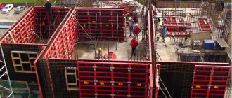
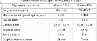
The most practical is a panel structure made of metal, or a combination of steel and wood. In this case, the frame is made of steel corners with additional stiffeners. Steel sheets with a thickness of at least 3 mm are attached to them.
If a combined type is used, then a plywood sheet or plastic panel is used as side elements. For fastening, this design uses brackets with springs, as well as various types of locks. The structure mounted in this way is characterized by increased strength and durability, but it has one drawback - installation of the structure requires a fairly large financial investment. Not in all cases such costs are justified from an economic point of view.
Therefore, the most popular option, attractive not only for its practicality, ease of assembly and low financial costs, is wooden formwork.
Material for formwork structures
Fences are made from different materials:
- wood - lumber, chipboard, plywood;
- polymers – polystyrene foam, polystyrene;
- metal shields.
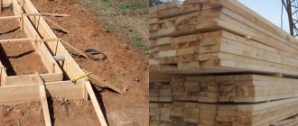
Tree
Wood invariably takes precedence in the creation of formwork fencing. In a country with vast areas occupied by forest, lumber is the most accessible and inexpensive building material.
Both edged boards and unedged material are used as fencing for pouring concrete into foundations, walls and ceilings. Unedged boards are used for small buildings in the household.
In all other cases, fences are made only from planed edged boards. Such structures form a high-quality smooth surface of the monolith and do not allow liquid solution to pass through.
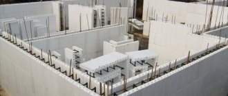
Polymers
Recently, many forms of polymer concrete barriers have appeared in civil and industrial construction.
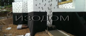
Formwork made of polystyrene panels
For vertical monolithic structures (walls, strip foundations) of small thickness, up to 30 cm, fencing made of foam plastic and polystyrene boards is used. This is explained by the low load-bearing capacity of polymer fences. If the thickness of the monolith is large, the pressure from the volume of liquid concrete can destroy polymer fences.
Ready-made polystyrene forms are used for strip foundations. Factory-made products must be certified indicating the maximum loading of molds with concrete.
Metal shields
Metal shields are reusable structures. The accompanying documentation for the shields must indicate the maximum load that the shield can withstand.
Only a design organization commissioned by the manufacturer can calculate formwork made from prefabricated metal panels. Based on the calculations, the thickness of the steel panel, the profile of the stiffeners and auxiliary elements are determined.
Adjustable formwork from metal panels
Along with removable metal panels, adjustable and mobile formwork is produced. Such structures are used for the construction of high monolithic walls. Mobile and adjustable fences are calculated by the design organization.
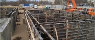
Wooden formwork for walls, columns and foundations
The main elements of this design are made of wooden panels of various thicknesses and sizes. The load-bearing supports are made of wooden beams.
Wire twists and ties are used as fastening elements.
Pouring concrete floors, vaults and beams requires the use of permanent formwork, the main part of which cannot be re-installed. In order to impart strength, this structure is supported by logs - round timber.
As a rule, coniferous and deciduous trees are used to make wooden formwork. It is very important to monitor the moisture level of the wood. This figure should not exceed 25%.
When formwork is used repeatedly, wood material of at least third grade with a minimum number of knots and defects is used.
It is necessary to ensure that the surface that is in direct contact with the concrete solution is perfectly smooth. Only in this case can you obtain a high-quality surface.
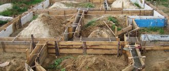
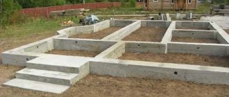
Foundation formwork
To ensure that the structure for pouring the concrete mixture that forms the foundation is of high quality and practical, wooden panels are most often used. The thickness of the material must be at least 5 cm, height 20 cm.
In order not to disturb the configuration of the future foundation, the formwork is limited on the inside with spacers, and on the outside it is fixed with special pegs, which should fit as tightly as possible to the board. With their help, you can reduce the pressure of the concrete mixture and maintain the desired shape of the foundation.
Internal struts also help in fixing the correct shapes, because the pressure of supports from the outside can significantly change the given parameters of the foundation.
When installing formwork for the foundation, do not forget that the height of the structure must correspond to the parameters of the future foundation. If the height of the walls exceeds the standard 20 cm, then special corners, clamps, spacers and struts are used to regulate the parameters of the erected structure.
Column formwork
In practice, a collapsible, movable formwork structure is used, made of four panels connected to each other with nails. The width of two panels in the structure must correspond to the parameters of the column. The remaining two panels should be wider in width than the parameters of the column by the thickness of the board.
Shields can be fastened with nails and steel clamps. Installation of fasteners is carried out only after the installation of the panels is completed.
Important! Fasteners must be selected in such a way that they can withstand the pressure of the concrete mixture during pouring and compaction.
Formwork of purlins and beams
The production of formwork for purlins and beams takes place simultaneously. For this purpose, the panels are installed in the form of a box without the top part. The quality of the fit of the panels to each other must be monitored. It should be so dense that the cement mortar does not leak.
Advice! Since the assembly and fixation of beams is carried out at a fairly high height, it will be practical and convenient to use scaffolding with a height of more than six meters.
Wall formwork
This process is quite simple from the technological side and from the calculation side. Two panels are installed parallel to each other, with an internal distance equal to the thickness of the future wall. To ensure the surface is perfectly flat, a system of supports is used to help fix the structure in level.
If the wall is less than 50 cm thick, then the presence of stiffeners will be sufficient for the formwork. When the surface thickness is over 50 cm, contractions are used. They are hollow beams with bolts, which I mount inside the structure. They can be simply removed after pouring the concrete and the holes sealed with cement.
A special case of calculation for the height of the interfloor foundation over 6.0 m
Let's assume that the formwork of a monolithic floor is installed to a height of 9 meters. In this case, the calculations will be the most complex and time-consuming. First, we’ll figure out what kind of formwork is needed; we’ll leave the calculation on the calculator for later. If the thickness of the interfloor span is 45 centimeters or more, then we recommend using a structural forming system. It is also voluminous, but it belongs to more durable and large-scale structures that also act as scaffolding. It is assembled as a single cage, which ensures stability, system stability and reliability. Cup-lock fasteners are used during assembly. Now we will calculate the volumetric formwork of the floor using known parameters:
- measuring the distance from the ceiling to the floor (denoted H1);
- beam parameter (let’s denote the height H6);
- dimensions of the universal jack (Nd = 50.0 cm);
- parameters of the support-jack (let's denote Nod = 50.0 cm);
- the number of three-meter racks to increase the required height (denote Nst.3 m).
Calculate racks for floor formwork using the formula:
Nst.3 m=N ⁄ 3.0
In this formula, the unknown H is calculated using the formula:
N=H1-H6-N beat— N od
When calculating the formwork of the floor slab, it is taken into account that the components (supports and jacks) can also have a different height of 100-200 cm and 75 cm (respectively). The correct calculation of the floor formwork racks must take into account the individual calculation of the number of axles. To do this you will need to know the following parameters:
- width of the platform (denoted B);
- length of the platform (denoted by L);
- dimensions of the crossbar (located in the horizontal plane, let’s take Lр=150 cm);
- number of axes (denoted No).
The horizontal formwork is calculated using the following formula:
N0=(B/Lp+1)*(L/Lp+1)
Thanks to the structure of the forming structure, it is possible to optimally distribute the load across the supporting components. This increases the reliability and safety of the formwork. To complete the calculation of the formwork for floors over 6 m in height, it is necessary to
Calculation of wooden formwork
At the beginning of the calculation, we measure the perimeter of the foundation. Multiply the result by 2, since the concrete is poured between two boards of the erected structure
The height of the structure being erected is equal to the height of the foundation + 20 cm of margin. Additional height, when calculating, is necessary, since the entire structure must be higher than the level of the poured concrete mixture.
To calculate the required number of cubic meters of boards for installing the formwork, it is necessary to multiply the resulting perimeter length by the height of the board and multiply by the thickness of the board.
Advice! If the final result of the calculation is a fractional number, it must be rounded up.
Let's look at an example of calculating wooden formwork:
- house perimeter -100 m;
- foundation height = 0.5 m boards + 0.2 m stock = 0.7 m;
- board thickness -0.05 m.
Using simple mathematical calculations, we calculate: (100*2)*0.7*0.05=7 m3.
Normative documents
We advise you to read the official documents, which reveal all the secrets of formwork work. So, you can look at SNiP 3.03.01-87, where you will learn a lot of interesting things, in particular, that it was replaced by GOST R 52086-2003. One will cling to the other, and soon foundation formwork calculations will seem more difficult to you than foundation calculations. For this reason, we present in the article a fairly simple method for calculating the parameters of the formwork - more than one foundation of the house was filled with concrete, and the formwork calculated using this method perfectly withstood the load from the concrete mixture.
Fully recessed strip foundation
This type of tape is suitable for any buildings, except frames and houses made of SIP panels - for them its load-bearing capacity is excessive. It is made from FBS, monolithic reinforced concrete, and solid brick.
This type of foundation requires careful calculation - it is necessary to take into account the ground level, geological features (this type of foundation must rest on dense layers of soil with high bearing capacity); if basements are planned, their height is taken into account.
Such foundations are made 150-200 mm below the soil freezing depth. The groundwater level should be no higher than 500 mm from the bottom of the sand cushion, but it can be higher if you make very good waterproofing and drainage. Just like MZLF, a recessed tape can be rectangular and with a sole, but the second option is used in the construction of high-rise buildings; for low-rise construction this may be redundant.
The recessed strip base is made either monolithic or prefabricated from FBS blocks. A monolithic strip foundation is inferior to a block foundation on soft and crumbly soils - masonry joints make the structure flexible enough so that cracks do not form on it.
Melnich23 Member of FORUMHOUSE
A foundation made of FBS significantly speeds up the construction process, all reinforcement and other parameters have long been calculated by the designers, assemble it yourself calmly. With a monolith, only when tying the reinforcement you will curse everything, and there’s also the formwork and pouring!
Marking
Marking is carried out by marking on the ground both the external and internal boundaries of the future foundation. To do this, it is best to use pegs or reinforcement rods and ropes. But it will be more effective to use special devices, such as laser levels. Remember that large errors in markings will noticeably affect the appearance of the finished building.
To achieve ideal results you need:
- determine the axis of the structure being built
- use a plumb line to mark an angle, and from it, at an angle of 90 degrees, pull a rope to two more corners of the structure
- use a square to determine another angle
- check the angles, focusing on the diagonals. If the test gives positive results, pull a rope between them
- take on the internal markings, retreating from the external markings to the distance of the thickness of the future foundation
When you are finished with the markings, study the differences in the surface at the construction site and select the lowest point to measure the depth of the trench and eliminate the difference in the height of the foundation. If the building is planned to be small, then the depth of the pit can be 40 cm.
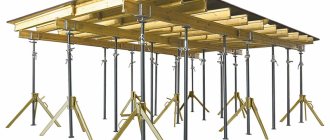
How to calculate the need for formwork for monolithic floors
A monolithic floor requires precise calculations.
When calculating formwork for pouring floor slabs, you need to know the height of the room and the designed thickness of the slab.
It is customary to perform two types of calculations of the need for lumber for pouring monolithic floors, which are used depending on the height of the ceiling in the building under construction.
If the ceiling height does not exceed 4.5 meters, the calculation is performed as follows:
Example:
- Floors are poured in a room 5 meters long and 4 meters wide.
- Floor thickness up to 0.4 m.
The area of the room is (5 x 4) – 20 m2. The need for telescopic racks to support the structure when pouring floors is calculated based on the area of the room. Consumption of telescopic supports – 1 pc. per 1 m2. The need for telescopic supports in our case: 20 m2: 1 + 20 pcs.
According to the technology, it is necessary to install one tripod on each rack; this operation is performed for safety reasons to prevent collapse. Tripod requirement: 20 pcs.
Wooden beams are fastened using special uniforks, which are purchased according to the number of racks. Requirement for uniforks: 20 pcs.
The calculation of the need for wooden beams is carried out based on the established consumption of materials - 3.5 pm of beams per 1 m2 of poured floor. Requirement for beams: 70 pm.
The consumption of plywood sheets is calculated based on the area of the room and the plywood sheet (take, for example, laminated plywood with sheet dimensions of 1525 x 1525), taking into account cutting losses (K-1.1). Requirement for plywood: (20: 2, 3256) x 1.1 = 9.45 l.
In total, you will need 10 sheets of laminated plywood with a thickness of at least 18 mm.
We recommend watching a video showing how to correctly install finished materials when pouring a monolithic floor.