Reinforced concrete floor slabs simultaneously serve as enclosing and load-bearing structures of buildings or structures.
Another function that is assigned to these structural elements is to ensure the overall geometric immutability of the spatial frame of the frame.
This is achieved by combining load-bearing vertical elements with a horizontal disk within each floor. To ensure the collaboration of walls, columns or pylons with floor slabs, it is necessary to define hinged or rigid nodes for their connection, which, in turn, depends on the nature of the support of the floors on the walls.
What does the concept mean?
Floors always operate in a building within one floor, taking permanent and temporary loads from their own weight, the mass of floors, equipment, furniture and people using the room.
When external forces are applied, internal forces arise in the element , which determine the geometric section and make it possible to calculate the span structure according to 2 groups of limit states.
At the same time, in the floor slab, along with the loads applied to it, support reactions arise, which are concentrated in places where the elements rest on walls or point vertical structures. These reactions are distributed over the support area and the larger its area, the smaller the load on each cm2 of the vertical element.
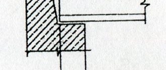
Thus, the depth of embedding of the floor in the wall is an important parameter that affects both the value of the supporting transverse force Q in the slab and the axial force N arising in the wall or column. Also, the size of the embedment affects the possibility of local crushing or chipping of the reinforced concrete product during load transfer .
Advice from professionals
Floor slabs are placed on the walls in strict accordance with the design and industrial documentation for the construction of the structure. The “box” of the upcoming object is designed in such a way as to guarantee the best depth of support - without breaks around the perimeter, as well as pinching.
If you need to order floor slabs, you should contact IS GROUP. We are ready to provide various designs to any region of the country. Here you can find various road slabs, airfield slabs, FBS blocks, PILES, floor slabs and many other reinforced concrete slabs. Delivery is carried out by rail. If there is no company in your city that can provide you with building materials, then be sure to contact us by phone.
Source
SNiP requirements
The depth of embedding of the floor slab into the wall is standardized based on the requirements of SNiP 2.08.01-85 (“Residential buildings”), as well as SP 335.1325800.2017 (“Large-panel structural systems. Design rules”).
According to the information contained in the reference tables of these documents, developed on the basis of static calculations for 2 groups of limit states, the minimum and maximum required value of floor support is:
- 40 mm when supported on 4 sides. The same condition when supported on 3 sides (if the contact surface runs along both long walls).
- 50 mm – in case of laying the slab on two supports in a span of up to 4200 mm. The same value is required when supporting the floor on 3 sides, if the contact line passes through only one of the two long walls.
- 70 mm – when supported on 2 walls with a span from 4200 to 6000 mm.
- 90 mm – if there are two supports and the floor length is more than 6000 mm.
If we are talking about a monolithic frame of a building, then rigid embedding of horizontal and vertical reinforced concrete elements is achieved when the ceiling is fully supported by the wall. As the contact area between the surface of the wall and the ceiling increases, the uniformly distributed load decreases, which makes it possible to reduce the embedment depth.
Important! As a rule, when installing prefabricated slabs such as PC or PB, builders play it safe and provide a standard embedment size of 120 mm, which is a multiple of ½ the linear size of a standard clay brick.
Armopoyas
Before installing the floors on the main structures, a monolithic reinforced belt is installed. It is carried out along the perimeter of the area of the main walls, along their entire width. Formwork is installed along the edge, then a reinforced frame of longitudinal, transverse and vertical reinforcing bars is mounted and filled with concrete.
When constructing an armored belt, the following requirements must be met :
- The height of the armored belt is from 20 to 40 cm (not less than the height of a standard aerated concrete block).
- The width must correspond to the width of the supporting element.
- The thickness of the reinforcement is at least 8 mm. The frame is tightly knitted with wire or fastened by welding.
- The concrete must match the brand of mortar used for masonry. The recommended grade of concrete used is at least class B15.
The armored belt serves to evenly distribute all loads. It also contains reinforcement fasteners, which are designed for reliable installation of interfloor ceilings. Since the armored belt is a cold concrete layer, it is provided with a thermal insulating coating.
Attention!
Floor slabs are installed only after the monolithic reinforcing belt has completely dried.
Installation methods
There are 3 main ways to support span structures on walls, each of which has both advantages and disadvantages:
- On both sides – the slab operates according to the classical beam scheme, as a bending element, under the influence of permanent and temporary loads. Suitable for installation in any room.
Pros: the design lends itself to elementary calculations, eliminating errors when selecting the type of floor.
Disadvantages: the increased value of support reactions leads to the need to ensure deep embedding of the span element into the wall to increase the contact area. - On three sides. The design is used when it is necessary to create a two-light space in a high room, or when constructing a loggia in the plane of the building facade. There are 2 subtypes of this support:
- Two short and one long sides.
Two long and one short sides.
- On four sides – the slab covers the entire space of the room with a single structure. It is used when special requirements are imposed on the room (for example, to ensure the tightness of the ceiling).
Pros: minimal pressure on the supports eliminates local collapse. It is allowed to reduce the area of contact between the ceiling and the wall.Disadvantages: when the aspect ratio of the slab is a/b or b/a < 2, the structure begins to work as if supported along the contour and requires double calculation in the longitudinal and transverse directions. This leads to an increase in the number of working reinforcement and, accordingly, an increase in the cost of the structure.
Pros: in both cases, the contact area increases compared to support on 2 sides. Accordingly, the pressure from the weight of the slab is reduced by 1 cm2, and the embedment depth can be reduced.
Disadvantages: the overlap ceases to obey a linear relationship when calculated using 2 groups of limit states.
When supported, uneven deflections occur when one long side lies completely on the support, and the second acts as a span structure, deforming under load. If next to such a slab there is a floor element supported on 2 sides, then the difference in deflections can be noticeable to the naked eye.
In practice, prefabricated reinforced concrete slabs supported on 2 sides are most often used, since this design is considered optimal from the point of view of installation and operation under load.
Useful video
The video clearly explains why it is impossible to lean deeply into the wall. But I would argue with the maximum depth of 30 cm. It should be no more than 15 cm.
The ceiling is a very important component of any capital building. Their use is also closely related to leaning on walls. Let's try to understand this topic in more detail.
How is the scheme drawn up?
When preparing a detailed design for a living room or public building, the support scheme for floor slabs depends on both the design, design and functional parameters.
When creating a drawing with the layout of reinforced concrete slabs, the designer takes into account the following factors :
Requirements of regulatory documentation.- Thickness of wall structures. For example, if the thickness of the internal brick wall is 250 mm, the ceiling supported along the contour can only be sealed to a depth of 40 mm.
However, if the design scheme provides for supporting the slabs on both sides of the wall, then the total embedment depth will be 80 mm.As a result, a technological gap of 170 mm will remain at the end of the vertical structure, and 20 - 30 mm is sufficient to form an installation joint. This leads to the designer artificially increasing the embedment depth to avoid the appearance of free space.
- Load-bearing wall material. If the upper rims of masonry are combined with a monolithic reinforced concrete belt, then its homogeneous structure allows it to withstand the requirements of SNiP. When support occurs on a brick or large-block structure, the human factor can affect its local strength, as a result of which the embedment should be performed in excess of standard requirements - up to 120 mm.
- Floor slab span. Here it should be taken into account that when installing an extended slab (6 m or more), the deflection can reach 30–40 mm, due to which the product is deformed and the contact area with the wall may decrease. In this regard, it is necessary to artificially increase the depth of the ceiling.
- Availability of effective thermal insulation. The condition concerns support on the load-bearing part of the outer wall. The floor slab must be located within the warm contour of the building to avoid the formation of cold bridges. Therefore, the support should be provided in such a way that the thermal insulation layer does not become thinner.
- Seismic activity of the area where installation work is carried out - for such floors, an increase in the support area is provided, as well as embedded parts for organizing welds.
The diagram should show the amount of embedding for each element on the floor . If the designer has achieved universality and provided a uniform embedment depth, this fact should be indicated in the notes to the graphic materials.
Supporting floor slabs on walls: design parameters
But it is not always possible to guarantee the best support depth. In this case, it is necessary to carry out calculations to calculate the smallest probable value. Similar activities are carried out by competent experts when studying design and industrial documentation. Without the Help of Others, it is little possible to think through it, in the absence of certain knowledge and abilities, since it is necessary to take into account a large number of characteristics: all types of functioning loads; the required degree of seismic resistance of the structure; long weights of reinforced concrete slabs; load-bearing wall thickness; the presence of thermal insulation and finishing material in the “wall cake”.
Rules for designing interface nodes
When carrying out a detailed design for the installation of floor slabs, in addition to the basic layout of the elements, it is necessary to provide detailing of the nodes , indicating all the nuances when pairing horizontal and vertical elements.
With external walls
The working drawing of the interface between a prefabricated reinforced concrete floor slab and a vertical enclosing structure should show the following details:
- Sectional view of a slab of a given thickness.
- The complete composition of the external wall, including cladding, backfilling and insulation.
- The depth of embedding the structure into the wall.
- Fastening elements to ensure connection (c/p mortar, embedded parts).
- If there is a reinforced concrete belt, a section along this element.
- Scheme of reinforcement of the interface.
- The presence of an elastic insert at the end of the plate.
- Scheme of filling the space between the ceiling and wall cladding.
- If provided for by the project, a diagram of a clean floor with a connection point to the internal part of the vertical enclosing structure.
- When detailing a unit on a typical floor, an image of the overlying external wall.
If the floor slab simultaneously rests on sections of the wall with different designs (for example, at the location of the lintels above window openings), then the assembly must be duplicated for all situations.
With internal carriers
When detailing the support of the slab on internal load-bearing walls, all elements of the drawing are indicated similarly to the algorithm described above. If there are additional design parts, they are also indicated on the unit :
- If the slab is not located in the extreme span, the designer depicts 2 horizontal structures and describes solutions for their connection.
- If the pairing of elements involves twisting or welding, then such parts are also indicated in the project with the designation of the pitch, seam length and other features.
- If there are ventilation ducts located in the thickness of the load-bearing internal wall that affect the installation diagram, such sections are drawn out in a separate drawing.
All additional consumables included in the project are also displayed in the specification for the drawing, indicating their brands and quantities.
Recommendations for use
You must understand that this structural unit is very important for the entire house, both at the design and construction stages. Plus, one more point should be taken into account, which is directly related to the reliability of the ceiling - brickwork, or rather the contact of the wall with the foundation (Find out here how to lay brick partitions).
There are two main points to consider here:
- The reliability of the foundation of the house, which must be designed for high loads. It is necessary to avoid those places where the foundation can be weakened, which will lead to uneven shrinkage of the structure, resulting in curvature of the ceiling.
- The width of the foundation should in no case be less than the brickwork. In this case, deformation of the load-bearing walls is inevitable - the load of the ceiling will affect the bricks and weaken the cement mortar.
You also need to focus on the thickness of the slab in relation to the thickness of the load-bearing wall. And this is provided that high-quality building bricks are used that comply with standards and GOSTs.
Installation technology
When installing prefabricated concrete floor slabs on a construction site, a typical interface is performed according to the following algorithm :
- The laying of load-bearing walls is completed 2 - 3 rows before the design floor height.
- A reinforced monolithic belt is arranged along the support lines of the slabs, allowing the support reactions from the floor to be evenly distributed throughout the entire volume of the masonry. In some cases, the project does not provide for such a structure, and the installation of span structures is carried out over an underlying layer of rigid c/p mixture.
- An underlying layer is applied on top of the belt, smoothed over the entire intended area of support for the slab.
- A sling bracket or chains are attached to the ceiling element through mounting loops.
- The lifting mechanism lifts the slab to the desired level, and the installers carefully bring it to the support area.
- A truck or tower crane slowly lowers the slab onto the support platform under the control of the installers.
- If there is a slight deviation in the position of the structure, workers correct the element with crowbars or a sledgehammer through a wooden block.
- The following floor elements are laid using a similar principle.
- When the installation of prefabricated concrete products is completed, workers caulk the seams with a rigid cement-sand mixture.
- Reinforcing anchors are installed in the mounting loops of the slabs, which are subsequently intersected “crosswise”.
- The anchors are welded together, and the hinges are pressed to a horizontal surface with sledgehammers.
Upon completion of the installation work, the installation of monolithic sections begins, if the layout of the slabs provides for such a design solution.
About hollow reinforced concrete products
Errors in laying the floor.
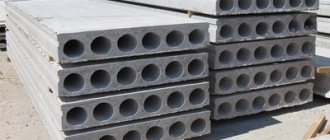
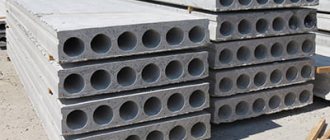
It is difficult to understand the issue if you do not know what floor slabs are. These are structural elements of permanent buildings, made of reinforced concrete, for the installation of floors between floors. Inside along the entire slab there are voids of various shapes, most often round.
Products are manufactured according to standard designs - a series of drawings that indicate design features and dimensions. The length of the elements is 1.5-12 m. Modern production technologies make it possible to cut slabs of the required length in increments of 100 mm. The width of the product is made into 4 types: 1000, 1200, 1500 and 1800 mm.
The standard distributed load for which each element is designed is 800 kg/m2. The slab can have a thickness of 16-33 cm depending on the design and length, the most common size is 22 cm.
Floor slabs are practically irreplaceable products. An alternative is a floor made of wooden beams or monolithic reinforced concrete. Wood is inferior to reinforced concrete in terms of load-bearing capacity, and the construction of a monolithic structure is a complex and expensive process.
Errors during the work process
Calculation of the area for supporting the floor slab on the walls is a responsible process, the correct execution of which determines the safety of the operation of the future structure.
If the designer makes mistakes, deviates from regulatory requirements, or omits important details when performing interfaces, serious consequences may occur :
- If the embedding is not deep enough, local crushing of the masonry may occur, which is fraught with the loss of geometric immutability of the entire structure with subsequent collapse.
- When deep embedding, zones of freezing of the structure and condensation from the dew point in the room may form.
- When walking through ventilation ducts, partial trimming of the end of the slab may be necessary.
- If the actually erected walls have a slight deviation from the vertical axis, and the designer did not provide for a margin when calculating the support, the entire floor structure will no longer meet the requirements of SNiP.
Thus, when calculating the support of the floor slab on the walls, all the features of the installation of the structure should be taken into account - from the values recommended by regulatory documents to the human factor and possible deviations of the structure from the design dimensions.
Features and purpose
It is appropriate to start the conversation about the use of floor panels with the fact that if the installation technology is violated, problems very quickly arise in them. Periodically it is reported that ceilings are collapsing in different places. Immediately after this, it becomes impossible to use the buildings normally.
Slabs or floor panels can rest either on a column or on an external wall. In any case, they are located horizontally.
The purpose of using slabs is to absorb the load exerted from above, with partial transfer of it to the vertical supporting structures of the house. In most cases these are standard products. The advantage of ready-made slabs is:
- reliability;
- ease of use;
- no special requirements for use;
- retention of vapors, gases and water;
- zero fire hazard.
Minimum Maximum Limits
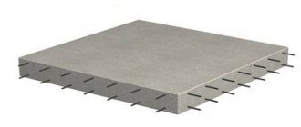
Modern technologies make it possible to implement almost any design solution. Thus, with the help of a monolithic slab floor, you can confidently cover a span of 6x6 m. Additional support points will not be needed. Such a problem can be confidently solved:
- a plate resting on 4 sides (10 cm thick);
- bottom mesh 10 mm;
- upper mesh 6 mm.
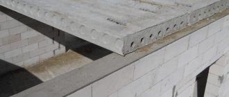
In most residential buildings built of brick, the end part of the hollow core slab should extend 9 cm onto the wall. The largest figure is 12 cm. The most accurate information can be obtained through special calculations. When laying a precast slab with voids on a panel wall, the minimum limit is 5 cm and the maximum is 9 cm.
If the wall is made of aerated concrete or foam blocks, these figures are 12 and 25 cm, respectively.
When using a ribbed slab, all the smallest and largest parameters remain the same as for hollow products. In both cases, they start from a single-span beam design. The parameters for supporting slabs for a wooden house deserve special attention. In this case, the walls must have a thickness of at least 250 mm. The smallest support value is 1 cm; the largest, according to various sources, is 16, 22 or 25 cm.