The use of reinforcement technologies for monolithic floor slabs in low-rise residential construction is a prerequisite. Concrete and metal in monolithic structures complement each other. Concrete protects the reinforcing bars and provides a strong floor surface. The reinforcement takes structural loads and protects the concrete layer from destruction.
As a result, the structure receives a strong and durable floor. To enhance its strength and stability, in addition to the supporting reinforcement, the structure is provided with a crown that connects the frame being installed with the ends of the reinforcement of walls, columns, beams, and pylons.
For reinforcement, metal rods with a diameter of 6-25 mm made of smooth (AI) or ribbed (AIII) steel are used. Specific parameters are indicated in drawings, diagrams and reinforcement specifications.
Additional strengthening, span calculation
Additional strengthening of single reinforced areas (areas of high overload and the presence of holes) is carried out with single iron rods with a length of 400 - 1500 mm, depending on the loads and span lengths:
- the lower part of the mesh is in the middle of the slab;
- the upper part is located on supports.
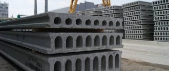
The rolled products used affect the relief of the ceiling; the fascias are placed in 2 or 1 directions. The advantage of openwork increase is the likelihood of reducing the thickness of the finished product near the same areas.
Supporting reinforcement protects the slab from cracking in wall areas.
The calculation of the reinforcement slab for the floor slab must be carried out with absolute accuracy, since the reliability of the entire structure as a whole will depend on this process. Some experts in the field of calculating reinforcement for a floor slab argue that the calculation should be made uniquely for almost every case, since many factors are different, including the dimensions of the slab itself.
It is worth considering that rolled metal will have a huge impact on the load-bearing capacity of the floor. And the advantage of the mesh used is the reduction in the thickness of the entire structure as a whole, but this is after all the “rough work” has been completed.
In absolutely any building, the best guarantee of quality work will be the correct and accurate calculation of the reinforcement for the floor slab. And when performing the calculation itself, it is necessary to comply with all the norms of technological progress, many of which are indicated above.
Advantages and disadvantages of monolithic frame technology
Monolithic reinforced walls have the following advantages:
- the one-piece construction without seams is strong and reliable, it does not blow through, and temperature bridges do not form;
- a smooth, even surface allows you to begin finishing work without prior preparation;
- building construction in a short time;
- monolithic houses have an open layout;
- increased service life of reinforced concrete structures;
- complex architectural curved elements and arches are made quite easily.
Disadvantages of monolithic walls:
- low sound insulation;
- mandatory wall insulation;
- the ability of concrete to conduct vibrations.
Calculation of accurate data
So, in order to make the correct calculation of the reinforcement for the floor slab, it is necessary to start from the initial data, since for each building they are unique and therefore it is much easier to compare and display accurate data on size, thickness, height, material, material class and other indicators regarding the building .
Accurate calculation of reinforcement for the floor slab, initial information:
Components of floor slab reinforcement.
- The dimensions of the building (initial stage) plan are 6x6 meters, taking into account the transverse walls, the dimensions of which should not be more than 3 m.
- The calculated thickness of the floor tiles is 160 mm.
- The exact height of the entire section of the floor, taking into account the steel reinforcement, is equal to – h0 = 14 cm2.
- If we take reinforcement made of carbon fiber, then the data is equal to h0 = 14 cm2.
- The construction material is concrete grade B20, the calculations are equal to:
- Rb = 117 kg/cm 2, Rbin = 14.3 kg/cm 2 Eb = 3.1*10 '5 kg/cm.
- Steel reinforcement has a class - A-500C.
- Rs = 4500 kg/cm2, E2 = 5.5*10 '5 kg/cm.
- Fiberglass reinforcement has the AKP-SP class, then the data is equal to:
- Rs = 12,000 kg/cm2, E = 5.5*10 '5 kg/cm.
Step-by-step instruction
Preparation
The initial stage is inspection of the fittings before purchase. Usually it is packed in packs with product tags. They indicate the brand, weight and diameter, batch number, heat and other data. In the case when the material is purchased without a design, the required amount of metal is purchased by weight at the rate of 80-100 kg per cubic meter of monolithic flooring.
During the work process there will definitely be waste and scraps will remain, so the material is purchased with a reserve of approximately 10%. If for some reason it is planned to use more reinforcement than the specified norm, then this implies redundancy and irrationality of the slab reinforcement.
The rods must be smooth, without obvious kinks or wrinkles, without pronounced manifestations of rust in the form of “flakes”; a small coating of rust is acceptable.
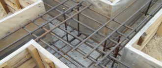
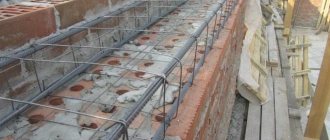
The frame includes longitudinal and transverse rods and special-purpose products. The reinforcement works most effectively with the optimal location of the upper and lower mesh of the frame - they should be located in the thickness of the concrete as close as possible to the top and bottom of the structure, respectively. Otherwise: the reinforced frame must be tightly compressed with concrete, having a sufficient external protective concrete layer. Control of the thickness of the protection from the bottom and sides of the concrete layer is ensured by installing standard plastic clamps.
They are manufactured in various versions according to their intended purpose, for example, for installation on a base of sand and crushed stone or for fixing a concrete layer on the side surfaces of the formwork. You should not place various bricks or stones under the reinforcement if you can use inexpensive products for fixation.
The required distance between the meshes is ensured by installing “frogs” - homemade products made from 10 mm periodic profile.
Laying reinforced frame
Reinforcement already cut to size is supplied to the work site. Installation of the reinforced frame in the ceiling is carried out approximately according to the following scheme:
- All transverse rods are laid out along the shortest distance from one supporting wall to another. Longitudinal rods are laid on them in increments of approximately 3 m, and all intersection points are connected. It turns out like a sketch of the bottom layer.
- Next, all the longitudinal rods of the bottom row are installed with the required or design spacing. Fixation with wire is performed every two intersections. There is no need for a tie in each node, since the wire does not perform any other functions in the operation of the frame other than fixing the reinforcement in a given position. Welding is not used for several reasons: high temperature weakens the rods and can damage the formwork, and the process itself is labor-intensive and time-consuming.
- Tying the rods is done using special hooks. This simple device is used not only by amateur builders, but also by professional monolithic workers. Automatic knitting guns are used only for large volumes of work. By the way, the use of various kinds of devices for a screwdriver when tying reinforcement does not indicate the advancement of the work performer, but rather his lack of professionalism.
- If the length is insufficient, the rods are connected to each other with an overlap, the length of which should be in the range from 30 to 40 rod diameters, at least three knitting knots are performed. Overlaps in adjacent rows are spread to different directions.
- After the lower mesh is completely installed, “frogs” are installed. The installation step is calculated for a person weighing approximately 90 kg - he must move along the grid without its deflection. To work without a project, a standard solution is used: a step of 80x80 cm, with reinforcement of 12 mm and a cell of 20 cm. The frogs are aligned along a single line.
"Frog"
- The guide rod is routed along the “frogs” as closely as possible over the bottom reinforcing rod.
- Between the laid guides, reinforcing bars are laid without fixation in an amount equal to the number of corresponding lower bars.
- Next, additional products are placed on the lower grid in accordance with the project. These can be releases, U-shapes, reinforcement fittings for openings, communication channels, sleeves and other elements.
- The reinforcement of the upper mesh is placed on the guides with fixation at all intersections; it is better if the rods are located exactly above the lower reinforcement.
- Then the rods laid without fixation are lifted with hooks and tied to the upper reinforcement every two intersections.
- At the last stage, the assembled frame is lifted using mounting crowbars, and clamps are installed under it.
Technical difficulties for performers often arise when lifting rods placed without a ligament on the lower net. This operation requires certain skills. Then the debris is cleared from the structure, and control measurements of protective layers and other parameters are carried out. After which the frame is ready to receive concrete.
Assembly of load structures, their calculation
| No. | Type of structures | Formulas for accurate calculations | Load data kg/m² | ||
| 2nd floor. Missing data | – | – | – | ||
| 1. | Stove (160) | g = 0.16m * 2.7 m/m '2 = 0.432 m/m '2 | 432 | 1.1 | 475 |
| 2. | C.-p. screeds are equal (30) | g = 0.03*1.8 m/m '2 = 0.054 m/m '2 | 54 | 1.1 | 60 |
| 3. | Ceramic tiles | Missing data | 27 | 1.1 | 30 |
| 4. | Weight indicators | Snip = 2.01 0.7 – 85* | 50 | 1,3 | 65 |
| 5. | Loads, useful type | Snip = 2.01 0.7 – 85* | 150 | 1,3 | 200 |
| 6. | Data output No data | – | – | 830 | |
Calculation of reinforcement for a floor slab during deformation using steel reinforcement
a. Selection of cross-section, calculation data
Determination of maximum data using the formula:
M = g*l2/8 = 0.83 mn / m * (3m)2/ 8 = 0.93 t * m
Determination of the coefficient, where =1(m) using the formula:
A0 = M*y/ b*h02R6*y62 = 93,000 kg/cm * 0.95/ 100 cm*13cm2 * 117 kg/cm = 0.045, n=0.0975
Indicators of the cross-sectional area where the reinforcement has class A-500C according to the formula:
A2 = M*y/n*h0*R2 = 93,000 kg/cm * 0.95/ 0.975*13 cm* 4500 kg/cm2 = 1.55 cm2
The basic data at the bottom of the entire reinforcement is accepted: Ø8 A-500С, taking into account the step of 200 (As = 2.51 cm2)
b. Calculation of reinforcement for a floor slab during deflection
The presence of a constant load on the floor itself is equal to 0.63 t/m².
The presence of a temporary load on the floor is 0.2 tons/m².
Maximum values for these long-term floor loads:
Mdl = g*ll2/8 = 0.63mh/m*3m2/8 = 0.71 mh * M.
The maximum values for these temporary loads on the floor are Mxp = g*l2/8 = 0.2 mh/m*3m2 / 8 = 0.22*m.
Reinforcement of slabs depending on support
A coefficient that takes into account the type of load and loading pattern S = 5/48 - for a beam with constant uniform load data y = y = 0.
Design of various concrete and iron structures made of heavy materials.
The coefficient for determination is equal to – k1, k2, k3.
Mn = f2/b*h0 * Ea/Eb = 2.51 cm2/100 cm * 13 cm * 2*10 '6 kg/cm / 3.1*10 '5 kg/cm2 = 0.012.
k1 = 0.64, k1 = 0.43, k2 = 0.10.
Axle irregularities under the simultaneous action of constant, long-term and short-term loads, which are calculated by the formula: 1/p = 1/Ea*Fa*H02 = Mkp/k1kp + M – k2 *b*n2*Rbin / k1 = 1/2* 10'2 kg/cm * 2.51 cm2 *13'2 cm2 * 22,000 ru * cm/ 064 + 71000 kg*cm – 0.1*100cm * 16 cm2 * 14.3 kg/cm2 = 1/848380000 * 34 375 + 71000 – 36 608/ 0.43 = 0.000135 1/cm = 13.5*10′-5 1/cm.
The maximum deflection data in the middle of the span are: f = 1/p *S*l2 = 13.5 * 10'-5 1/cm * 5/48 * 300'2 cm2 = 1.27 cm. f = 1/200 = 300 cm/200 = 1.5 cm. Fm = 1.27 cm = f = 1.5 cm.
These conditions are met with the adopted reinforcement, where (Ø8 A-500С in increments of 200). Calculation of reinforcement for a floor slab during deformation using fiberglass reinforcement (AKP-SP).
The tile load and design data are similar.
Calculations are made based on deformations for some reinforcement options.
The initial data, as well as the characteristics of the materials, are presented in the initial data.
Do-it-yourself pouring and grounding of the slab
Grounding is carried out after installation of the frame. To do this, install a ring made of galvanized material. It is located on the outside of the base and is equipped with connecting bars for fastening lightning rod elements and draining precipitation.
Then the concrete solution is poured. The process is carried out continuously until the formwork is completely filled. Vibratory pressing removes air bubbles from the mixture. Strengthening of the structure occurs within 28 days.
Calculation of AKP-SP data
c. With AKP-SP fittings Ø 14, in increments of 200
A2 = 7.69 cm2.
Coefficient data to accurately determine k1pr * k2pr * k3pr data.
M = Fa/b*h0 = Ea/Eb = 7.69cm2/100 cm * 14 cm * 550000 kg/cm2 / 3.1 * 10'2 kg/cm = 0.0098.
K1rp = 0.664, k1 = 0.043, k2 = 0.10.
Axle data curves under simultaneous actions, constant, long-term, short-term loads.
1/p = 1/Ea*Fa*h2 = Mkp/k1kp + M – k2 *b*n2*Rbin / k1 = 1/2*10'2 kg/cm * 2.51 cm2 *13'2 cm2 * 22,000 ru * cm/ 064 + 71000 kg*cm – 0.1*100cm * 16 cm2 * 14.3 kg/cm2 = 1/848380000 * 34 375 + 71000 – 36 608/ 0.43 = 0.000135 1/cm = 13.5*10′-5 1/cm .
The maximum deflection data in the middle of the spans are: f = 1/p *S*l2 = 13.5 * 10′-5 1/cm * 5/48 * 300'2 cm2 = 1.29 cm. f = 1/200 = 300 cm/200 = 1.5 cm. Fm = 1.27 cm = f = 1.5 cm.
The conditions are met, the accepted reinforcement is calculated correctly (Ø14 AKP-SP, taking into account the step equal to 200
d. For valves of AKP-SP class Ø 10, in steps of 100
Longitudinal section of the slab.
A2 = 7.86 cm2.
These coefficients are equal – Kpr * k1 * k2.
M = Fa/b*h0 = Ea/Eb = 7.69cm2/100 cm * 14 cm * 550000 kg/cm2 / 3.1 * 10'2 kg/cm = 0.0098.
K1rp = 0.664, k1 = 0.043, k2 = 0.10.
Data on the curvature of the axis for constant, long-term, short-term loads.
1/p = 1/Ea*Fa*h2 = Mkp/k1kp + M – k2 *b*n2*Rbin / k1 = 1/2*10'2 kg/cm * 2.51 cm2 *13'2 cm2 * 22,000 ru * cm/ 064 + 71000 kg*cm – 0.1*100cm * 16 cm2 * 14.3 kg/cm2 = 1/848380000 * 34 375 + 71000 – 36 608/ 0.43 = 0.000135 1/cm = 13.5*10′-5 1/cm .
The maximum deflection data in the middle of the spans are:
f = 1/p *S*l2 = 13.5 * 10′-5 1/cm * 5/48 * 300'2 cm2 = 1.29 cm. f = 1/200 = 300 cm/200 = 1.5 cm. Fm = 1.27 cm = f = 1.5 cm.
fm = 1.27 cm = f = 1.5 cm – the conditions are met, the accepted reinforcement is calculated correctly (Ø14 AKP-SP, taking into account the step equal to 100).
e. For fittings of class AKP-SPØ 8, taking into account a pitch of 100, calculation
The data is calculated using the formula:
A2 = 5.05 cm2.
Coefficients for exact determinations are k1*k2*k3.
M = Fa/b*h0 = Ea/Eb = 7.69cm2/100 cm * 14 cm * 550000 kg/cm2 / 3.1 * 10'2 kg/cm = 0.0098.
K1rp = 0.664, k1 = 0.043, k2 = 0.10.
The curvature of the axis is affected by the simultaneous actions of constant and long-term (and non-long-term) loads of different nature. Calculate using the formula:
1/p = 1/Ea*Fa*h2 = Mkp/k1kp + M – k2 *b*n2*Rbin / k1 = 1/2*10'2 kg/cm * 2.51 cm2 *13'2 cm2 * 22,000 ru * CM/064 + 71000 KG * CM - 0.1 * 100CM * 16 CM2 * 14.3 KG/CM2 = 1/848380000 * 375 + 71000 - 36 608/0.43 = 0.000135 1/CM = 0.00021 1/CM = 21 * 10 ′ -5 1/cm.
The maximum deflection data in the middle of the spans are:
f = 1/p *S*l2 = 13.5 * 10′-5 1/cm * 5/48 * 300'2 cm2 = 2 cm. f = 1/200 = 300 cm/200 = 1.5 cm. Fm = 2 cm = f = 1.5 cm.
All conditions are met using reinforcement, where (Ø8 AKP-SP, taking into account the pitch equal to 200).
Why do you need a frame made of reinforcement?
Concrete is an artificially created building material, which contains a binder and various fillers (sand, gravel) and water. The exception is asphalt concrete. It does not contain water. The mixture of all components hardens over time and becomes a monolith that is very resistant to destruction.
Having so many positive qualities, concrete, under certain loads, becomes a brittle material.
Monolithic blocks do not tolerate bending and stretching. In an already built house, when the soil subsides, in some place a longitudinal load will act on the concrete monolithic foundation, which can lead to deformation of the block or its destruction.
The same problems can arise at the corners of the building. Subsidence or swelling of the soil will cause bending load and, as a result, tensile load.
Cracks appear. Reason: incorrect determination of soil properties; the soil along the length of the foundation is heterogeneous and takes the load differently in different areas. To reduce this effect on concrete, reinforcement is used, which will help protect against such influences.
Conclusion
1. Reinforcement of an interfloor slab with a span that does not exceed 3 meters using steel reinforcement, then the data will be Ø8 A-500C taking into account a step of 200. 2. Reinforcement of the slab taking into account various spans and the use of reinforcement made of fiberglass, then The data can be of several options:
- Ø14 automatic transmission-SP, taking into account the pitch equal to 200;
- Ø10 AKP-SP, taking into account the pitch equal to 100.
3. If you use a mesh as reinforcement, the material of which is Ø8 AKP-SP, and even taking into account a step of 100, then the maximum data deflections of the slab will be greater than all existing aisles, which is not desirable.
Installation of formwork
Professional formwork for pouring such slabs can cost a fairly large amount of money, approximately the same as the cost of the slab itself along with the work. However, do not be upset, if the house is being built on your own, you can get by with ordinary 50x150 mm boards or plywood. Plywood and boards may later be needed to line the roof and ceiling, which means you would still need to spend this money.
Today there are quite a large number of companies that rent out telescopic stands and formwork. Renting racks can cost approximately 70-100 rubles per 1 m² of area.
The formwork installation process should be carried out in stages:
- Racks with tripods should be placed in rows, and the distance between them should be 1-1.2 m.
- The longitudinal beam is laid on top of the racks, after which the racks must be extended to the required height.
- A transverse beam is laid on the longitudinal beam (laying can be done lying down). The beam will need to be knocked down into a single mesh, after which plywood will be laid on it.
- After the plywood flooring is completed, using a level you will need to completely level the entire slab. Next, reinforcement begins.
Comparison of reinforcement options, calculation output
| Type of fittings | Diameter calculation. | Step indicators | AS Credentials | Deflection data (cm) | Ultimate deflection data (cm) |
| A-500S | 8 | 200 | 2.51 | 1.27 | 1.5 |
| AKP-SP | 14 | 200 | 7.69 | 1.29 | |
| 10 | 100 | 7.86 | 1.30 | ||
| 8 | 100 | 5.05 | 2.00 |
The comparative stage “calculation of the reinforcement slab” is quite simple. After all, you probably noticed that the formulas used to derive accurate calculation data are similar and practically the same in many cases. This calculation method has been accepted for quite a long time and not only in construction topics, but also in promoting economic statistics and for faster and more accurate calculations various accounting data.
If we consider a comparison of two completely different types of fittings as an indicator of functionality, then the calculation will show that the AKP-SP is several times superior to its rival. A person has a huge number of possibilities when using this product. However, this calculation shows that although the A-500S has numerous capabilities, the quality of work is rather different in a positive direction, which is not observed in the AKP-SP.
Excavation
The soil is marked according to design standards, increasing its perimeter by 50 cm on each side for the installation of a drainage system
- The soil is marked according to design standards, increasing its perimeter by 50 cm on each side for the installation of a drainage system. It is worth remembering that the slab itself should protrude beyond the walls of the future house by 10 cm on each side.
- Pegs are driven into the ground and a marking cord is pulled. The axes of the future slab should also be drawn.
- The soil is removed from the pit to a depth of 60 cm. At the same time, you should carefully monitor the quality of the soil being removed. If early digging of soil is observed on a building site, then the loosened soil must be removed layer by layer until you reach layers untouched by a shovel. Here, according to the instructions, you will have to remove layers of soil around the entire perimeter of the pit in order to completely level it. After this, the bottom of the pit is compacted and filled with sand to the design level of the pit. If this is not done and the foundation is mounted on soft soil, then the force of the house’s pressure on the slab will simply break it over time precisely in the place of loose soil.
- A drainage system is laid around the design base area in the form of special perforated pipes with their slope towards the storage well or central storm drain.
- Then you should lay a layer of crushed stone 20 cm thick and carefully compact it according to the principle of laying a sand cushion.
- Now we install the formwork from high-quality wooden panels. Their height should be at least 40 cm. It is advisable to clean the inner walls of the formwork. The formwork is fastened with bolts, screws or self-tapping screws. From the outside, the wooden frame can be supported with wedges for greater stability.