When constructing buildings and structures for the installation of floors and wall masonry over various openings, often, in addition to the use of reinforced concrete beams and factory-made lintels, there is a need to install individual monolithic reinforced concrete beams directly at the construction site.
As for construction using permanent formwork, individual beams are an integral structural part of it. If the design and design documentation is available, questions regarding their design do not arise.
But on the sites of individual developers, the practice of building according to architectural designs, the so-called sketches, is very common, and calculations of monolithic beams have to be performed during construction.
Let's look at how you can calculate a reinforced concrete beam yourself.
Determining the type of beam support
Depending on the type of support (see Construction of bored piles), the calculation method is selected. Let's consider the main types of supports for reinforced concrete beams on load-bearing structures.
Hinged type of support.
This is considered the case when a prefabricated reinforced concrete beam is installed in the design position.
Moreover, the design does not provide for any embedded parts for subsequent rigid connection with the structural elements of the building. As a rule, with this type of support, the width of the plane of support on load-bearing structures (walls, columns) does not exceed 20 cm.
A rigidly clamped beam.
To consider a beam to be rigidly clamped at the ends, the conditions must be as follows: the beam is concreted simultaneously with adjacent structures as part of a monolithic wall, its structure contains embedded parts for subsequent rigid connection with other structural elements.
When concreting, it creates monolithic joints for structures.
Multi-span support.
If it is necessary to cover several successively located spans, the beam is supported on several supporting structures (columns, partitions between windows).
Such support is calculated as multi-span if the supports are hinged). If the supports are rigid, then the calculation is carried out for each individual span, as if for an independent beam.
Cantilever support.
We are talking about this type of support when one or both ends of the beam do not have supports, as well as when the supports are indented from the ends by a certain distance (overhang from the support).
For example: part of the floor slab is extended beyond the wall in the form of a canopy. Such a slab can be considered a beam with a cantilever support.
Purpose of the calculator
The calculator for calculating reinforced concrete floor beams is designed to determine the dimensions, specific type and grade of concrete, quantity and cross-section of reinforcement required for the beam to achieve the maximum load-bearing capacity.
According to SNiP 2.03.01-84 “Concrete and reinforced concrete structures”, the dimensions of reinforced concrete floor beams and their structure are calculated according to the following principles:
- The minimum height of the floor beam must be at least 1/20 of the length of the opening to be covered. For example, with an opening length of 5 m, the minimum height of the beams should be 25 cm;
- The width of the reinforced concrete beam is set according to the ratio of height to width in ratios of 7:5;
- The beam reinforcement consists of at least 4 reinforcements - two rods at the bottom and at the top. The reinforcement used must be at least 12 mm in diameter. The lower part of the beam can be reinforced with rods of a larger cross-section than the upper part;
- Reinforced concrete floor beams are concreted without interruptions in pouring, in one portion of the concrete mixture, so that there is no delamination of the concrete.
The distance between the centers of the stacked beams is determined by the length of the blocks and the set width of the beams. For example, the length of the block is 0.60 m and the width of the beam is 0.15. The distance between the centers of the beams will be equal to - 0.60 + 0.15 = 0.75 m.
Possible errors during reinforcement
When reinforcing concrete, technology violations are often observed, leading to a decrease in strength characteristics.
When carrying out work, you should pay attention to the following points:
- The use of aluminum rods, waste, substandard metal products of arbitrary shapes, and wire is not allowed as working reinforcement. The use of such materials that do not have the required performance properties will lead to deformation of the concrete and the appearance of cracks.
- It is not allowed to pre-heat the bend areas; use a cutting tool to facilitate their bending. This leads to weakening of the rods and, consequently, to unpredictable consequences when operating under the design load. Bending operations must be carried out under natural temperature conditions.
- Steel rods of class A400 and A500C can be bent at an angle of up to 90 degrees when using special equipment. The bending radius of the reinforcement should be equal to five times the diameter of the reinforcement. Bending at an angle exceeding 180 degrees leads to a decrease in the strength of the product by 10%.
Reinforcement in a reinforced concrete beam increases its strength characteristics, and it is able to withstand bending and tensile loads. When performing work in accordance with the recommendations, the safe operation of reinforced concrete structures is ensured throughout their entire service life.
Calculation of an individual reinforced concrete beam
As for construction using permanent formwork, individual beams are an integral structural part of it.
If the design and design documentation is available, questions regarding their design do not arise. But on the sites of individual developers, the practice of building according to architectural designs, the so-called sketches, is very common, and calculations of monolithic beams have to be performed during construction.
Let's look at how you can calculate a reinforced concrete beam yourself.
Calculation of floor beams
Independent calculation of a wooden floor beam is a long and tedious task that requires you to know the basics of engineering disciplines and strength of materials. Without certain skills and knowledge, manually selecting the material, calculating the required section or pitch of the beam is not only difficult, but sometimes impossible. However, we will try to tell you about the main characteristics that are needed for calculations and what algorithm our calculator uses.
Types of beams
Currently, wooden beams used for the manufacture of floors can be divided into two fundamentally different types:
Based on the name, it becomes clear that in the first case, it will be a solid piece of wood of a certain type of section (most often it is a beam with 2 or 4 edges), in the second case, it will be a laminated beam made of boards or LVL veneer.
Despite the low cost, for a number of objective reasons, wooden beams made of solid wood have recently been used less and less . The quality characteristics of this material are significantly inferior to laminated wood: the low modulus of elasticity contributes to the appearance of large deflections in the middle of the span (this becomes especially noticeable when the distance between the load-bearing walls is more than 4 meters), when drying, longitudinal cracks appear on the beams, which lead to a decrease in the moment of inertia of the deflection, Lack of impregnation exposes the wood to pests and rot.
Thanks to modern technologies, glued beams do not have such disadvantages . Their structure is homogeneous and the fibers are oriented in all directions - the overall strength and elastic modulus of the material increases, it receives protection from cracking, and special impregnation provides an increased level of fire safety and moisture resistance. These beams are allowed to be used for openings of 6-9 m and can be considered as a full-fledged analogue of an iron floor.
Advantages and disadvantages of reinforced concrete beams
Like any structure, a reinforced concrete beam has both advantages and disadvantages.
Advantages:
- High mechanical, chemical, biological and physical strength;
- Reinforced concrete beams do not burn;
- Resistance to bending, compressive, tensile and vibration forces;
- A properly manufactured beam in a damp environment only increases its tensile strength over time.
Flaws:
- Large mass, creating a load on the walls and forcing the use of lifting equipment during installation;
- The thermal conductivity is not high enough compared to wood;
- The cost of reinforced concrete products is higher than that of wooden beams and floors.
Scheme of destruction of a reinforced concrete beam
Requirements for fittings
Beams are reinforced with longitudinal and transverse rods, followed by knitting or welding. In the first case, a binding wire is used. For the reinforcement of monolithic beams and floor slabs, corrugated profile rods are used, which have a more than 3-fold reserve of tear-out resistance relative to smooth reinforcement.
Table of maximum tolerances for the number of rods in the beam section.
Work must be carried out in accordance with the requirements of SP 52-101-2003:
- for longitudinal reinforcement, use rods with a diameter of 10 mm or more;
- for non-tensioning elements, rods with a cross-section of 12 mm or more should be used, while for knitted frames used as supporting walls, their height should be at least 400 mm;
- longitudinal rods in frames must be placed at a distance from one another of at least 30 mm for the top layer and from 25 mm for the bottom chord.
Table of recommended sizes for rectangular beams.
The following requirements apply to reinforcing bars:
- the surface must be degreased;
- the presence of dirt, traces of paint compositions and other non-metallic decorative and protective coatings is not allowed on the rods;
- Before reinforcement, the surface must be cleaned of loose rust.
There is an opinion that the fittings should be moistened 7-10 days before installation. As a result, its surface will become covered with rust, which will provide better adhesion to concrete. Such rods bond better with the concrete mortar, but the presence of rusty peelings is not acceptable. More details in the article: “Is it possible to use rusty fittings?”
Principle of operation
According to GOST 26519-85 “Reinforced concrete structures of buried rooms with beam-type ceilings. Technical conditions" formula for calculating the payload of reinforced concrete floor beams consists of the following characteristics:
- Standard and operational load on floor beams with a certain coefficient of safety. For residential buildings, this load indicator is 151 kg per m2, and the safety factor is 1.3. The resulting load is 151*1.3=196.3 kg/m2;
- Load from the total mass of the blocks that fill the gaps between the beams. Blocks made of lightweight materials, for example, foam concrete or aerated concrete, the density of which is D-500, and a thickness of 20 cm will carry a load of 500 * 0.2 = 100 kg/m2;
- The tested load from the mass of the reinforced frame and subsequent screed. The weight of a screed with a layer thickness of 5 cm and a density of 2000 kg per m3 will form the following load - 2000 * 0.05 = 100 kg/m2 (the weight of the reinforcement is added to the density of the concrete mixture).
The payload indicator of a reinforced concrete floor beam is made up of the sum of all three listed indicators - 196.3+100+100=396.3 kg/m2.
How to determine the cross-sectional area of reinforcement in a reinforced concrete beam. Calculation example
Or you can use a ready-made program written in Excel
Download a program for calculating the cross-sectional area of reinforcement in a reinforced concrete beam:
After we have calculated the required cross-sectional area of the reinforcement , it is necessary to select the number of rods and their diameter.
The program implements a method for selecting reinforcement of only the same diameter, and if you need to select reinforcement for a beam with different diameters, then use the table of the cross-sectional area of the reinforcement:
By following these recommendations, you can easily calculate the required cross-sectional area of reinforcement in a reinforced concrete beam.
Determination of the load-bearing capacity of a reinforced concrete beam without reinforcement in a compressed zone
Given:
reinforced concrete beam 4.5 m long, h = 30 cm high, b = 240 mm wide, made of concrete grade M300, which corresponds to class B22.5. The beam is reinforced with class A-III (A400) reinforcement, two rods with a diameter of 18 mm at the bottom. Granite crushed stone was used as a coarse aggregate (as a result we have heavy concrete)
You need to determine:
what uniformly distributed load will such a beam withstand, provided it is hinged on supports.
Solution:
The calculation algorithm in this case is as follows: first, the height of the compressed zone of concrete is determined, then the value of the moment, and after that the value of the load can be determined. Well, now in more detail:
Beam span determination
Since it is advisable to take the length of the supporting sections of the beam at least h/2, in our case the design span will be l = 4.5 - 0.3 = 4.2 meters.
Determination of strength characteristics
We can immediately accept the calculated tensile strength of the reinforcement from the corresponding table Ra = 3600 kg/cm2 . The tables do not list the calculated resistance of class B22.5 concrete. However, nothing prevents us from determining this value by interpolation:
Rb = (11.5 + 14.5)/2 = 13 MPa or 13/0.0981 = 132.5 kg/cm2
and taking into account various coefficients that take into account the possible duration of the load, repeatability of loads, operating conditions of concrete, etc., for reliability, we will accept Rb = 132.5 0.8 = 106 kg/cm2 .
Two reinforcement bars with a diameter of 18 mm have an area As = 5.09 cm2 . This can be determined either directly from the formula A = nd2/4 or from the table.
Determination of relative height ho
If ho is not known to us, then for design reasons in this case the protective layer of concrete is a ≥ 1.8 cm, respectively ho ≤ 30 - 1.8 - 0.9 ≤ 27.3 cm. For further calculations we will take the value ho = 27 cm .
Determination of the height of the compressed zone of concrete
According to formula 220.6.5, the height of the compressed zone y is
(6.5)
Then
y = 3600·5.09/(106·24) = 7.2024 ≈ 7.2 cm
At the same time, we will determine whether this value is within the acceptable range
у/ho ≤ ξ R
7.2/27 = 0.267 < ξR = 0.531 (for class A400 fittings)
Determination of the maximum torque value
Since according to formula 220.6.3
M < Rbbу (h0 — 0.5у)
Then the moment value will be
M < 106·24·7.2(27 - 0.5·7.2) = 428613.12 kgf cm
those. the maximum permissible value of the bending moment will be M = 4286 kgf m
Determination of uniformly distributed load
Because
M = ql2/8
That
q = 8M/l2 = 8 4286/4.22 = 1943.46 kg/m
Those. the existing beam, provided that during its design and manufacture all design and technological requirements were met, can withstand a load of up to 1943 kg/m. If one or more concentrated forces act on the beam, then the final part of the calculation will be slightly different. However, often a concentrated load or loads can be reduced to an equivalent uniformly distributed one.
And if there is also reinforcement in the compressed zone of the section and you want to take its effect on the strength into account, then the calculation algorithm does not change, only the formulas become slightly more complicated:
Reinforcement calculation
Reinforcement is carried out according to pre-made calculations, which make it possible to determine the total area of the rods according to the specified operating conditions. Or vice versa - calculate the load-bearing capacity of the element based on the actual parameters of the existing reinforcement.
Calculations determine:
- rod diameter;
- reinforcement length;
- rod placement diagram;
- reinforcement consumption per 1 m3 of concrete.
To calculate the optimal method of beam reinforcement, the following parameters are taken into account:
- product dimensions;
- protective layer (distance from the edge of the rod to the outer wall of the concrete beam);
- value and type of load (point or distributed).
I, as a person who has been working in monolithic construction for more than 10 years, always recommend not to make calculations yourself. It is better to provide the necessary data to the design bureau, they will calculate and provide you with a finished project, and you will be able to independently reinforce the beam using it.
Types of beams and purposes of their reinforcement
Beams are elements of building structures that take on external loads, made of concrete and reinforced with steel rods. According to location, method of location and manufacture, they are divided into:
- monolithic – freely placed, including console ones;
- prefabricated - elements composed of several parts, forming two-span or multi-span structures.
An example of a frame made of reinforcement to strengthen a monolithic beam of a semicircular shape.
Beams can have a cross-section of various shapes: rectangular, trapezoidal, T-shaped or I-beam, box-shaped. In construction they are used as elements of floors and foundations. According to SP 52-101-2003, the section width is assigned starting from 150 mm, and the height - from 300 mm to 1200 mm in increments of 100 mm, and then in multiples of 300 mm.
Thanks to the use of reinforcement technology, the following characteristics of reinforced concrete beams are improved:
- the load-bearing capacity of the structure is improved;
- crack resistance and rigidity increases;
- resistance to stress increases.
Beam dimensions
When ordering or making reinforced concrete beams with your own hands, you should clarify their dimensions and shape in advance. The following standardized requirements according to existing state standards will help with this:
- The length of the reinforced concrete L must be 40 cm greater than the distance between the load-bearing walls;
- The height H of a concrete beam must be at least 1/20 of its length;
- Width B of reinforced concrete beams must have a ratio of at least 5:7 to their height.
Factory floor beams are manufactured in accordance with GOST 24893.1-81, 24893.2-81 and GOST 20372-90, so the dimensions of these products are known in advance. To make a beam structure yourself, you will need to carry out the appropriate calculations, which will be easier and more accurate to calculate using an online calculator or desktop computer program:
Calculator for calculating reinforced concrete structures
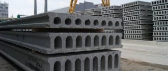
Reinforced concrete products not only have different sizes depending on their purpose, but also different sections (for example, round beam, rectangular section, square beam, trapezoidal products, I-beams, L- or T-shaped) and functionality. The state standard for filling with concrete provides for two subtypes of products: solid and hollow. When choosing the size and purpose of the beam, it should be borne in mind that for interfloor floors, a beam made in accordance with GOST must withstand a mass load of ≥ 205 kg/m2 with a compressive and bending rigidity ≥ 1/250; for attic floors, the corresponding values are 105 kg/m2 and 1 /200.
Reinforced concrete beam of rectangular section
How to form a beam with your own hands
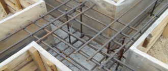
Before manufacturing reinforced concrete beams, they independently form a wooden formwork into which concrete will be poured. The internal surfaces of the formwork are covered with waterproofing films.
- A frame is assembled in the formwork from reinforcement Ø 12-14 mm, the minimum number of rods is 4 pieces, the overlap of rods is ≥ 800 mm, the connection is made with soft knitting wire;
- The frame must be completely hidden under a layer of concrete ≥ 50 mm thick to prevent metal corrosion;
- Concrete grade ≥ M 350;
- The volume of solution must be sufficient for pouring in one go;
- During strength development (up to 28 days), the concrete is kept covered under a film and periodically moistened.
Types of reinforced concrete beams
The figure above shows the different shapes and designs of reinforced concrete beams:
- Beam with a rectangular cross-section (Fig. No. 1);
- Beam with a T-shaped section (Fig. No. 2);
- Beam with an L-shaped section (Fig. No. 3);
- Purlin beam (Fig. No. 4);
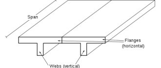
- Beam with an I-section (Fig. No. 5);
- Gable beam on two supports with an I-section (Fig. No. 6).
Such reinforced concrete products are also used to cover openings of windows and doors.
I-beam
Example of calculation of a reinforced concrete lintel
- It is necessary to obtain a reinforced concrete lintel 3 meters long, 0.4 m thick; hollow reinforced concrete slabs 6 meters long with a specific weight of up to 350 kg/m2 should be placed on the lintel on both sides (the total load on the lintel is up to 700 kg/m2);
- Estimated load value for 1 linear line. m: 700 x 6 = 4200 kg/l.m;
- Beam bending force: 4200 x 32 / 8 = 4725 kg/m.
Design dimensions: With a minimum lintel width of 0.4 m, its height can be taken as 0.2 m.
- Reinforcement and concrete classes: A0 = M / b x h20 x Rpr = 4725 / (0.4 x 0.182 x 1450000) = 0.251;
- According to the table below, η = 0.853 and ξ = 0.293 are determined;
- Calculated cross-sectional area of the reinforcement: Fa = M / η x h0 x Ra = 4725 / (0.853 x 0.18 x 36000000) = 0.000854 m2 or 8.54 cm2;
- Reinforcement is carried out with four rods Ø 18 mm. The cross-sectional area of the rod is 10.17 cm2;
- Reinforcement density: μ% = 100 x 0.293 x 145 / 3600 = 1.18%.
Table with data for calculations of reinforced concrete beams
When using reinforced concrete structures in individual or industrial construction, it is possible to more effectively distribute the load by mass that the floors produce on the load-bearing walls of the facility.
Necessary requirements for reinforced concrete beams
According to the design features of products, reinforced concrete beams are divided into:
- Regular type and gable lattice reinforced concrete slabs;
- Reinforced concrete single-pitch monolithic reinforced floors;
- Rafter beams with parallel rail clamps for equipment or other structures.
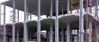
These prefabricated reinforced concrete structures are made in linear dimensions or in broken proportions, and are designed for the construction of heavy-duty floors and spans with heavy loads. An example would be spans for lifting special equipment, structures for warehouses or industrial premises.
Reinforced concrete beam in the crane workshop
Structures depending on the area of use of reinforced concrete beams:
- High-strength I-beams for reinforced concrete slabs in industrial or large-panel residential buildings;
- Beams for tying concrete structures, which are used only when constructing concrete lintels for window or door openings between powerful load-bearing walls;
- Units and elements of crane structures that serve to maintain balancing during operation of lifting equipment;
- Lattice reinforced concrete floors of a wide range of sections for all kinds of overpasses;
- Reinforced concrete beams for rafter systems in the construction of roof structures of low-rise residential buildings;
- Foundation reinforced concrete elements that are used in the construction of monolithic strip foundations.
Markings and dimensions of reinforced concrete beams
According to GOST, prefabricated reinforced concrete structures intended for the construction of interfloor, ceiling and other heavy ceilings are marked and have their dimensions according to the classification:
- The abbreviation BSP denotes structures of beam reinforced concrete rafter elements with parallel reinforced chords;
- Beams of the BSO brand are single-pitch reinforced concrete rafter structures;
- Beams marked BSD include gable rafter elements made of reinforced concrete;
- Sub-rafter reinforced concrete beams are marked with Cyrillic symbols BP.
Alphabetic Cyrillic characters can be supplemented with a digital code from various groups of numbers. For example:
- The type of beam is indicated by an alphabetic symbol, and the Arabic numerals following it indicate the standard size and span, the length of which is measured in meters;
- Also, Arabic numerals are used to indicate the category of a beam according to its load capacity, to indicate the class of reinforcement and the grade of concrete from which the beam is made;
- To indicate and classify auxiliary parameters and data, such as differences in design, operating conditions, etc.
Beam structures made of reinforced concrete can be purchased at the manufacturer, or poured into molded formwork with your own hands, which (the second option) is sometimes simply necessary due to the design features or dimensions of the product. Both the shape of the formwork and the dimensions, shape, characteristics and properties of the beam are pre-calculated, displaying the results in the design and specification. And, if for the manufacture of the beam itself you only need reinforcement and bulk materials, then to install the formwork you may have to use some curved shapes and patterns, since it is not always possible to assemble complex formwork from ordinary boards or plywood.
Beam markings
Reinforcement of ceiling or interfloor reinforced concrete beams for a house is carried out with 4 reinforcing bars with a diameter of up to 18 mm, but reinforcement of more powerful structures should be carried out by linking several belts and from thicker rods. Welded connections are not allowed - only bonding with soft wire, since when tensile, bending or compression forces are applied, the welding may burst, which will lead to a decrease in the strength of the beam and the entire building structure. To ensure that the entire reinforcing frame is in concrete, it is installed on special plastic stands, and the sides of the formwork are retreated by 3-5 cm.
To ensure that the beam is strong and monolithic, without cracks or deformations, it is watered with water during the entire period of concrete hardening and then covered with polyethylene. If this condition is not observed, the top layer of concrete will dry out faster under the influence of wind and sun, which will lead to unevenness of the entire concrete material and its cracking.