Diagram of two T-beams
T-beam
(or
tee beam
[1]), used in construction, is a load-bearing structure made of reinforced concrete, wood or metal, with a T-shaped cross section. The top of the T-shaped cross-section serves as a flange or compression member in resisting compressive stresses. The web (vertical section) of the beam below the compression flange serves to resist shear stress and to provide greater separation of associated bending forces. [2]
The T-beam has a major disadvantage compared to the I-beam (I-shaped) because it does not have a bottom flange that can withstand tensile forces. One way to make a T-beam more structural is to use an inverted T-beam with a floor slab or bridge deck connecting the tops of the beams. When done correctly, the plate acts as a pressure flange.
History[edit]
A T-beam is a structural element that can withstand heavy loads due to the resistance of the beam or internal reinforcements. In a sense, the T-beam dates back to the first time man built a bridge with a pier and deck. After all, a T-beam is in some sense nothing more than a post with a horizontal frame at the top or, in the case of an inverted T-beam, at the bottom. [3]The vertical part that carries the tension of the beam is called the web or rod, and the horizontal part that carries the compression is called the flange. However, the materials used have changed over the years, but the basic structure remains the same. {T-beam structures, such as highway overpasses, buildings and garages, have additional material added on the underside where the web meets the flange to reduce the T-beam's vulnerability to shear stress. [4] However, when one examines T-beam design more deeply, some differences emerge.
Requirements for beams
To meet the modern needs of builders, reinforced concrete beams are subject to numerous requirements:
- The strength value for each type of building is strictly selected: for residential premises and attic structures the maximum load is 105 kg/m2, for basement floors and interfloor ceilings – 210 kg/m2.
- The stiffness parameter for floors between floors should be equal to the ratio of 1 to 250, for attic floors - 1 to 200.
- The values of sound and heat insulation must exactly comply with the requirements for the premises being constructed according to regulatory documentation.
- If necessary, you need to sheathe the beam or select the type of filler for the interbeam openings.
Return to contents
Design[edit]
The T-beam, although simple in design, contains many interesting structural elements. Unlike an I-beam, a T-beam does not have a bottom flange, which saves materials but reduces resistance to tensile forces. [5] In garages, however, the absence of a bottom flange on a T-bar is an advantage since the rod rests on the flange, making the flange the top deck. T-beam structures come in a variety of sizes, lengths and widths depending on the structure and its required compressive stress. However, the simplicity of the T-beam is questioned by those who would rightly test more than one complex structure; For example, a group of researchers tested inverted pretensioned T-beams with round holes in the webs [6], with mixed but generally favorable results. Thus, in some cases, the extra time and effort put into creating a more complex structure pays off. A simpler question is what material or materials are used to construct the T-beams.
An example of calculating a T-section beam taking into account deflection
The strength calculation performed above (calculation for the first group of limit states) is usually insufficient for simply supported single-span beams and requires additional calculation for deformations. There are several methods for determining the deflection of reinforced concrete structures. In my opinion, the easiest way is to determine the approximate value of the deflection when calculating based on permissible loads.
Calculation based on permissible loads, which assumes elastic operation of the material and does not provide for plastic deformations in the compressed zone of concrete, gives the following results:
With the parameters defined above, the height of the compressed zone of concrete will be:
y = √3M/2b'fRb = √3·326765.6/2·76·105.3 = 7.826 cm
In this case, the required height of the compressed zone when calculating by deformations is determined by solving the following cubic equation:
y3 = 3As(ho - y)2Es/b'fEb (321.2.4)
and at Eb = 270000 kgf/cm2, Es = 2000000 kgf/cm2, will be approximately уf = 6.53 cm (ур = 5.234 cm).
Then at Ip = b'f(2yp)3/12 = 76(2·5.234)3/12 = 7264.8 cm4 the approximate deflection of the beam will be:
f = 0.83·5·10.456·5004/(384·270000·7264.8) = 3.6 cm > fu = 500/250 = 2 cm (according to SNiP 2.01.07-85)
This is a fairly large deflection and to reduce it, you can increase the number of beams, but you can also increase the height and cross-sectional width of the accepted number of beams, especially if this is necessary to do this to use a concrete mixture with large crushed stone. For example, with an increase in the height of the beam by only 2 cm - up to 17 cm and the width of the beam up to 11 cm and with the same reinforcement ho = 22.3 cm:
уf = 7 cm (yp = 6.174 cm), Ip = 76(2 6.174)3/12 = 11924 cm4, approximate deflection
f = 0.83·5·10.456·5004/(384·270000·11924) = 2.194 cm ≈ fu = 2 cm.
Note : the given method for determining deflection is not recommended by regulatory documents; moreover, to simplify the calculations, it was not taken into account that the load from the beam’s own weight will slightly increase. Nevertheless, this technique allows one to quickly determine the approximate value of the deflection and evaluate its effect on the operation of the structure.
Materials [edit]
Steel T-beams[edit]
The production process of steel T-beams includes hot rolling, extrusion, sheet welding and welding. The process of connecting two steel plates with large rollers by pressing them together, called a clamp fitting, is a common process for non-structural beams. The reality is that for most roadways and bridges today, it is more practical to use concrete in the structure. Most T-beam structures are made not only of steel or concrete, but of a combination of both, namely reinforced concrete. [7]Although the term can refer to any of a number of means of reinforcement, in general the definition is limited to the concrete poured around the reinforcement. This shows that when considering the materials available for a task, engineers must consider the possibility that no single material is suitable for the job; rather, a better solution may be to combine several materials. So steel and concrete together may be ideal.
Reinforced concrete T-beams [edit]
Concrete itself is brittle and is thus excessively subject to shear stresses at the T-beam surfaces where the web and flange meet. This is the reason why steel is combined with concrete in T-beams. Shear stress problems can cause flanges to fail, separating from the walls under load. [8] This could be disastrous if it happened in real life; therefore, there is a real need to reduce this possibility by reinforcing concrete T-beams. Such composite structures raise many questions regarding design considerations, including what the ideal distribution of concrete and steel might be: “To evaluate the objective function, the ratio of the cost of steel to the cost of concrete is necessary.” [9]This demonstrates that for all aspects of the design of composite T-beams, equations are prepared only when the appropriate information is available. However, there are design aspects that some may not have even considered, such as the possibility of using external fabric reinforcement, as described by Chajes et al., who say of their tested beams: "All beams failed in shear and with composite reinforcement showed excellent adhesion characteristics. Increases in ultimate strength from 60 to 150 percent have been achieved for externally reinforced beams.” [4] When it comes to resisting shear forces, external reinforcement can be considered. Thus, overall, numerous important aspects of T-beam design impress engineering students.
An example of calculating the strength of a T-section beam
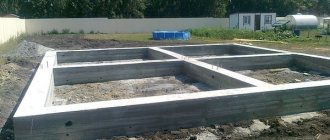
It is planned to have a monolithic ceiling in a residential area measuring 5x8 meters with 4 main beams. The preliminary accepted height of the main slab is 8 cm, the preliminary dimensions of the beams are 10x15 cm:
Figure 326.2
Note : In the general design diagram (Fig. 326.2.a), the dimensions are given in millimeters, and the cross-sectional dimensions of the beam (Fig. 326.2.b) are given in centimeters to simplify further calculations. To simplify the calculations, the structural reinforcement of the main slab is not taken into account.
1. If both the main slab and beams are concreted simultaneously, then the height of the main slab will be the height of the flange h'f, and the total height of the T-beam h = 8 + 15 = 23 cm, a = 2.5 cm, ho = 20.5 cm. For the floor it will be class B20 concrete should be used, with a design compressive strength of Rb = 11.5 MPa (117 kgf/cm2) and class AIII (A400) reinforcement with a design tensile strength of Rs = 355 MPa ( 3600 kgf/cm2 ). If the concrete mixture will be prepared at home (i.e. without proper control of the strength of the samples) and concreting will be carried out by non-specialists, the design resistance of the concrete should be reduced. SNiP SNiP 2.03.01-84 does not provide a reduction factor that takes into account the quality of work performed for such cases, and it is difficult to predict how much the above reasons can affect the design resistance of concrete. The approximate value of this coefficient can range from 0.5, if there is no self-confidence, to 0.9, if self-confidence is high. Further calculations will be made using the work quality factor γk = 0.9. Then the calculated value of concrete compression resistance will be:
Rb = 117·0.9 = 105.3 kg/cm2
2. The span of the beams is 5 m, while bсв ≤ 500/6 = 83 cm, the first condition is met. The beam in question is part of a monolithic floor, while the height of the slab is 8 cm > 0.1h = 2.3 cm, according to clause 2.2, the calculated width of the flange will be:
b'f = 152/2 = 76 cm
3. To determine the height of the compressed zone of the section, it is first necessary to determine the maximum bending moment acting in the considered cross section of the T-beam. And for this you need to know the loads acting on the floor.
When calculating the floors of residential buildings, the following value qvr = 400 kg/m2 can be used as the calculated live load. For beams with a pitch of 162 cm, the calculated live load per linear meter will be
qвр = 400·1.62 = 648 kg/m
Note: A more accurate value of the design load should be determined according to SNiP 2.01.07-85 “Loads and impacts”, which provides the values of standard loads. According to the specified SNiP for floor slabs in apartments of residential buildings, the standard value of the distributed load is 150 kg/m2. Then this value must be multiplied by the load reliability factor, at this value of the standard load the component is γн = 1.3 (1.4 according to the old standards). Thus, the calculated value of the temporary load without taking into account the screed, floor covering and possible other temporary loads will be
qsv = 150 1.3 = 195 kg/m2
As practice shows, if the temporary distributed load determined in this way is added to the temporary loads from the leveling screed, floor covering, etc., multiplied by the corresponding load safety factors, then the total live load will be slightly less than the specified 400 kg/m2. If the thickness of the future screed, the type of floor covering, the location of furniture and engineering equipment are known before the calculations begin, then the value of the total live load can be calculated more accurately. In this case, the value of the calculated temporary load can be reduced by 30-70 kg/m2. However, further calculations will be based on the above mentioned live load of 400 kg/m2.
Note : The installation of any partitions is not provided for in this calculation. If it is planned to install partitions along the floor, then separate beams should be provided for the partitions and calculated taking into account possible loads. An exception may be light gypsum plasterboard partitions, near which furniture will not be installed.
The constant load from the self-weight of the monolithic floor on one beam will be qп = (0.08·1.62 + 0.1·0.15)2500 = 361.5 kg/m. The load safety factor for concrete and reinforced concrete structures is γн = 1.1. Then the calculated value of the constant load will be qpr = 361.5·1.1 = 397.65 kg/m. Thus, the total distributed load on the beam will be:
qр = qп + qв = 397.65 +648 = 1045.65 kg/m
Then the maximum bending moment for a non-cantilever beam on two hinged supports:
Mmax = ql2/8 = 1045.65 52/8 = 3267.656 kg m = 326765.6 kg cm
Why this is so is discussed in another article.
4. Check the fulfillment of condition (326.1.2):
M = 326765.6 < Rbb'fh'f(ho - 0.5h'f) = 105.3·76·8(20.5 - 4) = 1056369.6
5. The condition is met, the reinforcement cross-section in the compressed zone can be calculated using formulas (220.6.6) and (220.6.7), then:
am = 326765.6/(105.3·76·20.52) = 0.09716
6. am = 0.09716 < aR = 0.39/1.5 = 0.26, which means that reinforcement is not required in the compressed zone, then the required cross-sectional area of reinforcement in the tension zone will be:
Аs = 105.3·76·20.5(1 - √1 - 2·0.09716)/3600 = 4.67 cm2
The diameter of the fittings can be selected according to the following table:
Table 2. Cross-sectional areas and mass of reinforcing bars.
7. To reinforce the beam, you can use 2 rods with a diameter of 18 mm, the cross-sectional area of the rods will be 5.09 cm2.
8. We check compliance with the required thickness of the protective layer of concrete with the selected reinforcement. The thickness of the protective layer according to clause 5.5 of SNiP 2.03.01-84 must be no less than the diameter of the reinforcement and ≥ 15 mm. In our case, the thickness of the protective layer of concrete will be:
hз = a - d/2 = 25 - 18/2 = 16 mm
The condition is not met, so for calculations a larger value of a should be taken. For example, with a = 27 mm ho = 20.3 cm.
am = 326765.6/(105.3·76·20.32) = 0.0991
Аs = 105.3·76·20.3(1 - √1 - 2·0.0991)/3600 = 4.71 cm2
9. The clear distance between the reinforcement bars will be 100 - 2a - d = 100 - 54 - 18 = 28 mm. This means that for concreting a beam, a concrete mixture with a maximum crushed stone grain size of 28 mm should be used. If you plan to use large aggregates, then you should either increase the width of the beam or increase the height of the beam, which will reduce the diameter of the reinforcement used.
Note : if the beams and slab will be concreted separately, then the beams should be calculated as elements of a rectangular section with a height equal to the height of the beams.
Problems[edit]
The problem with a T-beam compared to an I-beam is the lack of a bottom flange. It also makes the beam not as versatile due to the fact that the weaker side does not have a flange, making it less tensile strength.
Concrete beams are often poured as one piece with the slab, creating a much stronger T-beam. These beams are very efficient because the slab portion carries the compressive loads while the reinforcing bars located at the bottom of the beam carry the tension. A T-beam typically has a narrower shaft than a regular rectangular beam. These rods are typically spaced from 4'-0" to over 12'-0". The portion of the plate above the rod is designed as a one-way plate that extends between the rods. [ citation needed
]
Markings and sizes
According to existing standards, all prefabricated reinforced concrete structures for the construction of floors have their own markings according to the classification. Each beam is assigned its own standard size. The abbreviation BSP denotes reinforced concrete rafter beams with parallel chords. BSO beams are called reinforced concrete rafter, single-pitch elements, and BSD are called rafter, gable elements. Rafter structures are usually marked with the letters BP.
It is customary to append numbers to letter designations. The marking contains three groups of letters and numbers.
- To indicate the type (letter), standard size and span covered in meters (whole Arabic numerals).
- To identify the category by load-bearing capacity, the class of steel rods used and the grade of concrete mixture.
- To clarify additional characteristics, such as design differences, features of application conditions, etc.
Regardless of the area of application of the beams, there are three size indicators for which a clear calculation is required.
- Length (L). This value should be 0.4 m greater than the span length and extend beyond the edges of the supporting parts by 0.20 m onto the load-bearing walls.
- Height (H). The parameter must be equal to at least 5% of the length or 1/20 of it.
- Width (B). The ratio of this value to the height should be 5:7.
Return to contents
I-beams [edit]
Main article: Double Three
An I-beam or I-beam is a load-bearing structure that resembles two T-beams connected to each other. Double tees are manufactured from prestressed concrete using a pretensioning frame ranging from 200 ft (61 m) to 500 ft (150 m) in length. The strong connection of the flange (horizontal section) and two walls (vertical elements) creates a structure that can withstand high loads over long spans. Typical sizes for double tees are up to 15 ft (4.6 m) for flange width, up to 5 ft (1.5 m) for wall depth, and up to 80 ft (24 m) or more for span length. [10]
Theoretical basis of calculation
According to SNiP 2.03.01-84 and SP 52-101-2003, it is recommended to calculate T-sections without reinforcement in a compressed zone using the following provisions:
a) If the neutral plane (the boundary between the compressive and tensile zones of the section) passes in the flange (Figure 326.1.a), i.e. conditions are met:
RsAs < Rbb'fh'f(326.1.1)
M ≤ Rbb'fh'f(ho — 0.5h'f) (326.1.2)
And
ξ = у/ho < ξR (220.6.1)
then the calculation is performed as for a beam of rectangular cross-section with width b'f. The details of the calculation using this algorithm are described in detail in the article “Calculation of a reinforced concrete floor slab”. Here I will give only the basic formulas:
ξR is the maximum permissible value of the relative height of the compressed zone of concrete, determined by the following formula:
(220.6.2)
where Rs is the design resistance of the reinforcement in MPa. Also, the limiting value of the relative height of the compressed zone of concrete can be determined from the table:
Table 220.1 . Limit values of the relative height of the compressed zone of concrete
Note : When performing calculations by non-professional designers who are limited only to calculations for the first group of limit states, I recommend underestimating the limit value of the relative height of the compressed zone ξR (and the value aR) by 1.3-1.5 times. In this regard, a possible calculation option when y > ξRho is not considered further.
When determining the cross-section of reinforcement, the coefficient am is first determined:
(220.6.6)
when am < aR, reinforcement in the compressed zone is not required; the value of aR is determined according to table 220.1.
In the absence of reinforcement in the compressed zone, the cross-section of the reinforcement is determined by the following formula:
(220.6.7)
In formulas (220.6.6) and (220.6.7), the values of b are replaced by b'f.
Figure 326.1
b) If the neutral plane passes through the edge of the beam (Figure 326.1.b), then the calculation is performed based on the following condition:
M < Rbbу (h0 — 0.5у) + Rbh'f(b'f — b)(h0 — 0.5h'f) (326.2)
where (b'f - b)h'f = Aov is the cross-sectional area of the shelf overhangs.
In this case, the height of the compressed zone y is determined based on the following formulas:
RsAs = Rbby + Rbh'f(b'f - b) (326.3.1)
y = (RsAs - RbAov)/Rbb (326.3.2)
in this case, the height of the compressed zone is taken to be y ≤ ξRho.
When determining the cross-section of reinforcement, the coefficient am is first determined:
(326.4.1)
when am < aR, reinforcement in the compressed zone is not required; the value of aR is determined according to table 220.1 (see above).
In the absence of reinforcement in the compressed zone, the cross-section of the reinforcement is determined by the following formula:
(326.4.2)
2. Since the width of the T-section flange can be quite large, for example, for beams that are part of a monolithic beam floor, the beam flange width b'f is taken taking into account the following conditions:
2.1. The width of the flange overhang in each direction from the beam edge bсв = (b'f - b)/2 (not shown in Figure 326) should be no more than 1/6 of the span length of the element being calculated, and also no more than:
2.2. In the presence of transverse ribs (secondary beams when calculating main beams or main beams when calculating secondary beams, in which case the edge of the beam in question is considered longitudinal) or when h'f ≥ 0.1h, the calculated flange width b'f is taken equal to 1/2 the distance between the longitudinal ribs in the light.
2.3. In the absence of transverse ribs or when the distance between the transverse ribs is greater than the distance between the longitudinal ribs and for h'f < 0.1h, the design width of the flange is b'f = 6h'f.
2.4. For cantilever overhangs of the shelf (when calculating individual T-section beams that are not part of various types of floors):
a) for h'f ≥ 0.1h, the design width of the flange is b'f = 6h'f;
b) at 0.05h ≤ h'f < 0.1h, the calculated flange width b'f = 3h'f;
c) for h'f < 0.05h, shelf overhangs are not taken into account in the calculations.
2.5. When the height of the shelf overhangs varies, it is allowed to use the average height h'f in calculations.
All these, so to speak, are theoretical, and therefore not entirely clear, let's see how they can be applied in practice.
Links[edit]
- "Continuous span reinforced concrete bridge with beam tee" (PDF). Virginia Department of Transportation. December 2011. Retrieved April 25, 2015. Quote journal requires |journal=(help)
- Jump up
↑ Ching, Francis DK (1995).
Visual Dictionary of Architecture
. New York: John Wiley and Sons. p. 203. ISBN 978-0-471-28451-2. - Ambrose, James; Tripeny, Patrick (2007). Simplified design of concrete structures (8th ed.). Chichester: Wiley. paragraph 104. ISBN 978-0-470-04414-8. Retrieved April 26, 2015.
- ^ ab Chajes, Michael J.; Januska, Ted F.; Mertz, Dennis R.; Thomson, Theodore A., Jr.; Finch, William W. Jr. (May 1, 1995). "Shear Strengthening of Reinforced Concrete Beams Using Exterior Composite Materials". ACI Structural Journal
.
92
(3). DOI: 10.14359/1130. Retrieved April 26, 2015. - Furlong, Richard W.; Ferguson, Phil M.; Ma, John S. (July 1971). "A Study of Shear and Anchorage Reinforcement in Inverted T-Beams in Flexural Cap Beams" (PDF). Research Report No. 113-4
. Retrieved April 26, 2015. - Cheng, Hock Tian; Mohammed, Bashar S.; Mustafa, Kamal Nasharddin (3 March 2009). "Experimental and analytical analysis of pre-tensioned inverted T-beam with round holes in the web." International Journal of Mechanics and Materials in Design
.
5
(2): 203–215. DOI: 10.1007/s10999-009-9096-4. S2CID 136040255. - University, Jack C. McCormack, Clemson University, Russell H. Brown, Clemson (2014). Design of Reinforced Concrete (Ninth Edition, ACI 318-11 Code ed.). Hoboken, NJ: Wiley. ISBN 978-1-118-12984-5. Retrieved April 26, 2015.
- Paramasivam, P.; Lee, S.L.; Lim, T.Y. (9 January 1987). “Shear and moment strength of reinforced concrete beams.” Journal of Concrete Research
.
39
(140): 148–160. DOI: 10.1680/macr.1987.39.140.148. - Jump up
↑ Chou, Takashi (August 1977).
"Optimal sections of reinforced concrete T-beams". Journal of the structural department
.
103
(8):1605–1617. Retrieved April 26, 2015. - Gurley, Evan; Hanson, Kayla (October 13, 2014). "Strength to the double tee". Precast Solutions Magazine
. Retrieved April 26, 2015.