Explanation and form
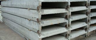
The abbreviation PKZH stands for large-panel reinforced concrete slab. It has an increased length, which is why it got its name.
The cross-section of the slab is U-shaped. Stiffening ribs increase the load-bearing capacity of the structure, which allows it to be used as a floor and roofing. On the underside they can be either sharp or rounded for safety.
V. MARKING AND Certification
34. The brand of the slab must be indicated on the top and bottom surfaces of each slab (in the center of the outer field).
On the side edge of the longitudinal rib of each slab (at a distance of no more than 1 m from the end of the rib) the following must be indicated: the brand of the slab, the date of manufacture and the brand of the manufacturer.
35. The manufacturer must provide each batch of slabs with a document that certifies the slabs’ compliance with the requirements of this standard and indicates:
a) name and address of the manufacturer;
b) batch number and date of its manufacture;
c) brand, design load and number of slabs;
d) strength of concrete;
e) results of bending tests of slabs (deflection and coefficient) indicating the test date;
e) number of this standard.
Dimensions and characteristics of PKZh slabs
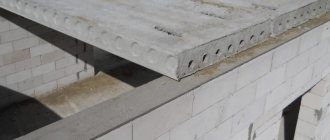
Large-panel slabs are used primarily in the construction of large industrial facilities, because they are not designed to produce a perfectly flat ceiling. Their characteristics, production and other requirements are regulated in GOST 21506-87. Design diagrams of products and design drawings of PZhK series slabs are contained in the album PC Series 01-106.
Regulatory documents regulate the dimensions of large ribbed panels:
- length – 5970 mm;
- width – 1490 mm;
- height – 300 mm;
- The mass of the plate is 1540 kg.
Characteristics of PKZh panels:
- maximum load – up to 780 kg/m²;
- water resistance – at least 2;
- frost resistance not less than 150;
- seismic resistance up to 9 points;
- operating temperature range from -40° to +50°C.
For the manufacture of slabs, concrete of a grade not lower than M200, reinforcing bars for the frame AI, AII and wire BP-I are used. The upper part and ribs of the panel are reinforced, and reinforcing mesh is placed in the lower part. Metal products are reliably protected from corrosion by a layer of concrete, which ensures long service life of the structures. The weight of the PKZh slab is unified, but may differ between different manufacturers due to the use of different concrete - light, heavy or silicate. Some manufacturers also produce slabs with other dimensions (1.5×6, 1.5×12, 3×6, 3×12 or 3×18), which will affect their weight.
III. TECHNICAL CONDITIONS
6. The slabs must be made of concrete grade “200”.
7. The slab ribs are reinforced with flat welded frames, the shelf - with welded mesh. Frames and meshes must be manufactured using resistance spot welding.
8. Welded frames are made from rods: with a diameter of up to 5 mm inclusive - from steel low-carbon cold-drawn wire in accordance with GOST 6727-53*; with a diameter of 14 mm or more - from hot-rolled steel of periodic profile in accordance with GOST 5781-61, grade St.5 in accordance with GOST 380-60; diameter 6; 8 and 10 mm - from hot-rolled round steel grades St.3 and St.3kp according to GOST 380-60.
________________
* GOST 6727-80 is in force on the territory of the Russian Federation. Here and further. — Note from the database manufacturer.
Welded mesh is made from low-carbon steel cold-drawn wire in accordance with GOST 6727-53.
Drawings of recommended slab reinforcement are given in the appendix (sheets 1-5).
Notes:
1. Instead of hot-rolled steel of periodic profile, it is allowed to use cold-rolled steel of periodic profile in accordance with GOST 6234-52 or, as an exception, hot-rolled round steel of grades St.3 and St.3kp in accordance with GOST 380-60, with a corresponding increase in the cross-section of the rods.
2. Hinges for lifting slabs must be made of round steel grades St.3 and St.3kp. The use of steel of other grades for this purpose is not permitted.
3. The quality of reinforcing steel, welded frames and meshes is checked in accordance with the current technical specifications for monitoring the strength and rigidity of reinforced concrete parts of prefabricated structures and technical specifications for welded reinforcement for reinforced concrete structures.
9. In all cases, at the ends of the longitudinal ribs, special steel parts must be installed, welded to the main working reinforcement of these ribs, intended for anchoring the working reinforcement and for attaching the slabs to the supporting structures using arc welding.
The recommended design of these parts is shown in the application drawings (sheets 2 and 4).
Note. By special order, it is allowed to manufacture slabs with additional metal embedded parts installed at a distance of 350-500 mm from the ends of the longitudinal ribs (for fastening the slabs to load-bearing structures adjacent to the transverse expansion joint or to the end wall of the building).
10. The thickness of the protective concrete layer is set:
a) for lower reinforcement in longitudinal ribs - 20 mm;
b) for lower reinforcement in transverse ribs - 15 mm.
Permissible deviations in the thickness of the protective layer in the ribs: +5 and -3 mm.
The thickness of the protective layer of the welded mesh in the slab flange (top and bottom) is 11 mm, permissible deviations are ±5 mm.
11. The appearance of the slabs must meet the following requirements:
a) curvature of the edges in the horizontal plane is allowed no more than 2 mm per linear meter of the slab, and for the entire length no more than: outward 5 mm and inward 10 mm;
b) sinks on the ribs and lower surface of the slab are allowed with a size of no more than 10 mm and a depth of no more than 5 mm in an amount of no more than two per linear meter of the slab;
c) on the upper surface of the slab, local sagging and irregularities with a height of no more than 5 mm and cavities of no more than 10 mm in size and no more than 8 mm in depth are allowed;
d) cutting the ends of longitudinal ribs is not allowed;
e) breaks on the lower edges and corners of the ribs are allowed to a depth of no more than 7 mm: only one break is allowed in one cross section;
f) on the surfaces of the ribs and flanges, shrinkage cracks with a width of no more than 0.05 mm are allowed;
g) exposed reinforcement is not allowed.
Notes:
1. Permissible chips and holes must be repaired before installing the slabs into the coating.
2. The requirement of clause 11g does not apply to steel anchor parts at the ends of longitudinal ribs, embedded parts, hinges for lifting slabs and to the ends of fixing reinforcing bars.
12. The strength and rigidity of the slabs during short-term bending tests in accordance with clauses 24-29 must meet the requirements of clause 30 of this standard.
13. When manufacturing slabs, step-by-step technological control must be ensured at all stages of production.
Application
PZhK floor and coating slabs are used in the construction of industrial structures:
- stadiums;
- production facilities and workshops;
- in road construction;
- sports facilities, etc.
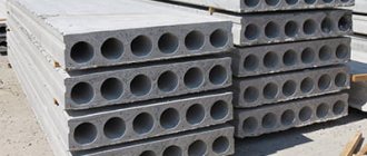
Ribbed slabs PKZh are indispensable in cases where there is a need to cover long interaxial spans of load-bearing walls. As a rule, the strength of conventional slabs with a rectangular cross-section and voids is significantly inferior to their ribbed “counterparts”.
The panels are used to cover the first floor above the basement and the last floor above the upper floor. The non-rectangular cross-section does not allow obtaining a flat ceiling; for this reason, the structures are not used in residential construction.
PKZh slabs on the first floor floors are insulated to reduce heat leakage through the basement. Thermal insulation of the roof top floor is also provided.
Floor load calculation
Before purchasing ribbed floor slabs, it is very important to reproduce important calculations. Thanks to them, it will be possible to get ahead of what load the slab must withstand. Based on the obtained value, it will be possible to purchase building material of a certain series, size and weight.
The video talks about the load on the floor slab:
As for the load, it can be very different: constant, temporary, uneven and uniform. When calculating, only a uniform load will be used, since it is considered the most common. Units of uniform load measurement are kg/m2.
What is the size of PC floor slabs according to GOST can be read here.
As a rule, the calculation of a ribbed floor slab in a building where people will live is based on a value of 400 kg/m2. If the height of the presented building material is 10 cm, and its weight will add another load of 250 kg/m2, the screed and floor covering will add another 100 kg/2.
It is this load that concentrates the combination of possible loads on the floors of the building in which people will live. However, calculations can also occur for higher loads. To be on the safe side, you should multiply the reliability coefficient, the value of which reaches 1.2. In other words, the uniformly concentrated load will be: 400+250+100)*1.2=900 kg/m2.
You can find out what the standards are for hollow-core floor slabs here.
Technical drawing PKZH
The photo shows a technical drawing of a ribbed floor slab:
Since the ribbed PKZh slab has a width of 100 cm, the resulting value must be considered as a plane load, which exerts its influence along the Y axis, and its units of measurement are kg/m2.
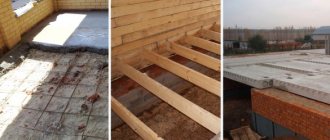
Installation features
The slabs are laid on load-bearing beams. The process cannot be done without a tower or truck crane. Its lifting capacity must be designed for the weight of the load.
How the slabs are installed:
- the ribs and ends of the panels are covered with cement mortar. This is done to secure the structure to the base;
- With four slings, the reinforced concrete product is hooked to the mounting loops and lifted to the platform;
- Above the installation site, the PKZh covering slabs are centered, leveled and lowered.
Installation of slabs is allowed only in a hinged manner, without pinching.
IV. ACCEPTANCE RULES AND TEST METHODS
14. Plates must be accepted by the technical control department (QCD) of the manufacturer in accordance with the requirements of this standard.
When accepting slabs, check:
a) strength of concrete;
b) appearance and dimensions of the slabs;
c) strength and rigidity of slabs;
d) thickness of the protective concrete layer.
15. The strength of concrete is determined by testing the cubes for compression, according to GOST 6901-54 “Methods for determining the workability of a concrete mixture and the strength of concrete.”
16. If, as a result of the test, the strength of the concrete does not satisfy the requirements of clause 6 of this standard, then the slabs are not subject to acceptance and can be submitted for secondary acceptance after achieving the required concrete strength.
17. The appearance is checked by inspecting each slab with proper measurements taken, in accordance with clauses 11b, c, d, e, f, g of this standard.
18. The width of the cracks is determined with an accuracy of 0.01 mm using a measuring lens.
19. Slabs that do not meet at least one of the requirements of paragraph 11b, c, d, e, f, g are not subject to acceptance.
20. To check the size and curvature of the slabs, 5% samples are taken from a batch of 200 slabs of the same brand.
Notes:
1. Each batch must consist of slabs made from the same materials and using the same production technology.
2. If the number of slabs to be accepted is not a multiple of 200, then the remainder is up to 100 pcs. added to the last batch, and the remainder is over 100 pcs. considered a separate party.
21. The dimensions of the slabs are determined with an accuracy of 1 mm using a metal measuring tool.
22. The curvature of the slab edges is determined by measuring, with an accuracy of 1 mm, the largest gap between the surface of the slab and the edge of a calibrated metal ruler attached to it.
23. If during the inspection it is established that at least one sample does not comply with the requirements of paragraphs 2 and 11a, then a secondary selection of samples from the same batch is made in the amount of 10%, which are subject to inspection.
If at least one sample from the newly selected ones does not meet one of the requirements of the above points, the slabs are accepted individually.
24. To check the strength and rigidity, four slabs are selected from each batch, of which two are tested first.
Note. For these tests, it is allowed to use slabs that do not meet the requirements of paragraphs 2 and 11 of this standard.
25. Bending testing of slabs is carried out with a load that is almost uniformly distributed according to the diagram shown in Figure 5.
Dimensions in mm
Damn.5
Two supports at one end of the longitudinal ribs must be articulated-fixed (knife), and the other two supports at the other end must be articulated-movable (on rollers). In the transverse direction, all supports can be stationary.
The slab is loaded in the form of a series of individual loads or a continuous load created by air cylinders or water.
The load in the form of a series of weights is placed in separate pillars with a plan size of no more than 430x430 mm over the entire surface of the slab. Gaps of at least 50 mm must remain between the pillars for the entire test period.
Loading is carried out in small fractions of the load, constituting no more than 25% of that indicated in Table 2.
table 2
| Stove brand | Test load (without slab’s own weight), kg/m |
| PKZH1 | 120 |
| PKZH2 | 200 |
| PKZH3 | 300 |
| PKZH4 | 400 |
| PKZH5 | 500 |
After applying each fraction of the load, the slab is held for 10 minutes before the next load begins.
Note. Bricks, stones, pig iron and other piece goods can be used to load slabs.
26. After applying the test load given in Table 2, the slab is kept under this load for 30 minutes and the deflections of both longitudinal ribs in the middle of their span are measured with an accuracy of 0.1 mm.
The deflection of the slab is calculated as the arithmetic mean of the deflections of two longitudinal ribs.
Note. When determining the deflection of longitudinal ribs, the settlements of the supports must be measured. The actual deflection of each rib is equal to the measured value in the middle of the span minus half the sum of the support settlement.
27. The rigidity of the slabs is characterized by deflection, determined by the formula:
, (1)
where is the deflection in mm, established in accordance with clause 26;
— test load in kg/m (according to Table 2);
160 - standard load from the dead weight of the slab in kg/m.
28. After fixing the deflection at a load equal to (160) kg/m, further loading of the tested slab is carried out until its destruction and the magnitude of the destructive load applied to the slab at the moment of its destruction is determined.
29. The strength of slabs is assessed using the value of the coefficient, calculated with an accuracy of 0.01 using the formula:
, (2)
where is the breaking load (without the dead weight of the slab) in kg/m, established in accordance with clause 28;
160 - standard load from the own weight of the slab in kg/m;
— maximum design load in kg/m (according to Table 1);
— coefficient of working conditions (according to clause 4).
30. If, as a result of testing each of the first two slabs, it turns out that the deflection calculated by formula (1) will not exceed 20 mm and the coefficient calculated by formula (2) will be equal to or more than 1.4, then no further tests are produced and the entire batch of slabs is considered acceptable.
If, when testing the first two slabs, the deflection of at least one of them is in the range of 20.1-23 mm or the coefficient is less than 1.4, but more than 1.2, then the remaining two slabs from those specified in clause 24 are tested.
If the deflection of each of the newly tested slabs is no more than 23 mm and the coefficient is not less than 1.2, then the entire batch of slabs is considered suitable.
If the deflection of at least one of the initially or subsequently tested slabs is more than 23 mm or the coefficient is less than 1.2, then the entire batch of slabs is not subject to acceptance.
Notes:
1. When testing slabs calculated taking into account the operating conditions coefficient of 1.10, a coefficient value below 1.25 is allowed only for one of the tested slabs.
2. If the results of testing the strength or rigidity of the slabs are unsatisfactory, it is allowed to relabel the given batch and present it for secondary acceptance at a reduced grade.
31. If in at least one of the tested slabs the longitudinal ribs are destroyed in a section 1.5 m long from the supports, or if the destruction of the transverse ribs or flange occurs before the destruction of the longitudinal ribs, then, regardless of the coefficient value obtained during testing, the entire batch of slabs is not subject to acceptance .
32. The thickness of the protective concrete layer is checked in two slabs subjected to bending testing by cutting out concrete in the middle of the span of longitudinal and transverse ribs, as well as in the center of each field of the slab - until the working reinforcement is exposed.
Note. The thickness of the protective concrete layer can be checked using other proven and reliable methods without destroying the concrete.
33. If the thickness of the protective layer in at least one of these slabs does not correspond to the indicators of clause 10 of this standard, these indicators are re-checked in the same manner in two more slabs selected from the same batch.
If the thickness of the protective layer in at least one of the newly tested slabs does not correspond to the indicators in clause 10, then the entire batch of slabs will not be accepted.
VI. STORAGE AND TRANSPORTATION
36. Slabs sorted by grade should be stored in stacks with the slabs laid in the working position in the correct rows.
37. Wooden spacers must be laid between horizontal rows at a distance of no more than 50 mm from the ends of the slabs. The dimensions of the gaskets must be no less than: length 1700 mm, width 100 mm, thickness 50 mm.
Pads must be placed under the bottom slab (adjacent to the base). The dimensions of the pads should ensure the strength and stability of the base under the stack.
38. During transportation, slabs must be placed in their working position on spacers under the ends of the slabs.
All gaskets must be the same size in thickness and placed in the same vertical plane, one above the other. Measures must be taken to ensure that the slabs are positioned strictly one above the other in the transverse and longitudinal directions and cannot move.
39. When transporting slabs on vehicles with single-axle trailers (dissolutions), the turnstile on the vehicle must be installed on a slide that allows for longitudinal movement of the support, and the turnstile on the trailer must be of the swinging type with pressure transferred to one point. When transporting slabs on spreaders, the overhang of the slab over the spacer should not exceed 750 mm.
40. During storage and transportation, measures must be taken to protect the slabs from damage and deformation.
Replacement
GOST 5781-61 was introduced to replace GOST 5781-53.
GOST 380-60 was introduced to replace GOST 380-50.