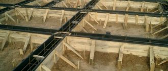
The construction of a formwork system (forms for hardening and giving concrete a specific shape) is the most important stage in the construction of monolithic buildings or reinforced concrete structures. It is responsible for the operational characteristics of concreted objects, reliability and safety of structures. Therefore, the installation process begins with the calculation of formwork elements for monolithic construction - floors, walls, foundations, internal partitions.
What does the concrete-forming structure consist of?
- supporting elements;
- shields and panels;
- connecting elements and locking systems;
- load-bearing elements: puffs, beams, jacks and others.
Let's figure out how to calculate the formwork for the floor, walls and foundation, its cost and the amount of materials needed. Project documentation will help you perform the correct calculation, which indicates the following necessary variables:
- the height of the walls and their actual length;
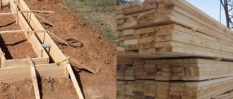
- characteristics of the material used (if the foundation formwork is calculated from wooden boards);
- height of the floor or foundation;
- area and thickness of the required floor (will help calculate the area of the formwork of walls and other parts of the building);
- perimeter of the house.
If the structure has a complex configuration and involves the use of different types of forming systems, then it is quite difficult to independently calculate the formwork for monolithic construction without errors. Especially if you have no experience in this field of work. Our company is ready to offer you specialist assistance and ready-made forming structures of various sizes. We will also help you make a preliminary calculation of the material for foundation systems, floors and wall formwork calculations using our calculator, which works online on the website. Having enlisted the support of a counting service, let’s understand the theory.
Calculation of formwork for all types of floors
When constructing monolithic buildings, three types of formwork systems are often used:
- interfloor span height up to 4.5 m;
- interfloor span height 4.5-6.0 m;
- the height of the interfloor span is over 6.0 m.
When calculating the floor formwork for 1 m2, you should know the permissible thickness of the object and the characteristics of the system components used. Let's assume that a building is being constructed with a ceiling height of up to 4.5 m. In this case, a floor thickness of less than 40 cm is allowed. The optimal formwork system option would be forming structures on telescopic racks. Support elements are available in various sizes. To perform the correct calculation of floor formwork on telescopic racks and correctly select its components, you need to consider:
- dimensions of the support beam - 40 cm (important when choosing the height of the telescopic stand);
- one support per 1 m of floor area - important when calculating the volume of telescopic racks;
- the maximum permissible load on the support is 1.5-2.0 tons.
These parameters will indicate how strong the floor formwork should be and will help calculate the number of supporting elements and components. Having counted the number of support pillars, you should take care of the stability of the entire structure. If you can’t do the calculation yourself, a table for calculating floor formwork based on the thickness of a monolithic object will help you. Returning to the stability characteristics of the system, let's talk about special tripods - components of the forming structure that are designed to hold supports. Their number will be equal to the number of telescopic stands.
If the calculation of the number of floor formwork posts has shown the need to use a large number of supports and tripods, you should not reduce it in an attempt to save money. Such a move, as our practice shows, in 8 out of 10 cases inevitably leads to collapse. The floor formwork calculation calculator proposed by our experts will help you determine the required number of supports and tripods.
When constructing a concrete-forming structure, 40 cm thick beams and plywood will also be required to create a flat and smooth surface for pouring the mortar. Calculate the floor formwork, taking into account the cutoff allowance of 1.1. The calculation formula involves dividing the floor area S by the dimensions of the plywood sheet. The result obtained is multiplied by 1.1. For a ceiling height of up to 4.5 m and a thickness of 40 cm, standard materials are taken (the formwork calculator takes into account their parameters) with increased moisture resistance (laminated sheets) - 122 cm × 244 cm or 150 cm × 300 cm. The formwork calculation program offered on this page will not help miss important parameters. The main thing is to enter the correct values into the form.
Types of formwork
All formwork systems, taking into account certain factors, are divided into the following types:
- according to placement in the plane, formwork sets come with vertical and horizontal installation;
- according to structural indicators, block, panel, sliding, adjustable, access or permanent formwork sets are divided;
- Based on the materials used in production, systems are divided into metal, wood, plastic or combinations;
- methods of influencing concrete divided formwork sets into warming systems, special ones, with or without an insulating layer;
- Depending on the frequency of use, formworks can be disposable or inventory-type.
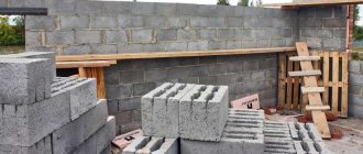
A practical option is a panel system made of steel or wood.
The frame base consists of metal corners with additional elements to provide rigidity. Sheets whose thickness starts from three millimeters are fixed to such a frame.
If a combined design is used, then the role of the side parts is given to plastic or plywood panels, the fastening of which is carried out by spring brackets or locking devices. The assembled formwork is characterized by good strength and a long service life, but has the only significant drawback - installation involves significant financial costs, which are not always justified.
The best option, known for its practicality, ease of installation and low financial costs, is considered to be a timber formwork structure
A special case of calculating formwork with a height from floor to ceiling of 4.5-6.0 m
When performing an independent calculation of the floor slab formwork or using a calculator, take into account that the thickness of the floor usually does not exceed 30 cm. When installing the formwork system, it is wise to use scaffolding towers - volumetric frame formwork. Let's consider a special case of how to calculate floor formwork with such characteristics. Our experts recommend using forming structures with “lock-cup” type connecting elements. With the described parameters, you don’t need a calculator to calculate the formwork, since to erect the floor you will need a basic set of forming structures. It includes:
- 8 pieces 2.50 m racks;
- 12 pieces 1.50 m crossbars;
- 4 pieces of insert;
- 4 pieces of jack stands with parameters 0.4-0.6 m;
- a similar number of uniforks for jacks (parameters 0.4-0.6 m).
If you use our frame formwork calculator, it will show that 1 tower is used to support 9 m2 of flooring. The area of the interfloor span is divided into equal squares with a side of 3 m. A tour tower is installed in the corners of each square. When calculating the formwork for a ceiling height of 4.5-6.0 m, it is taken into account that the amount of moisture-resistant plywood is carried out using the method already described above. To make it easier, use the floor formwork calculator on the website page.
Scope of application of formwork on vehicles
The use of this type of formwork is allowed when pouring a floor that rises no more than 4.5 meters above the floor and weighs less than 7 tons. In structures with large values for these indicators, volumetric beams are used. Telescopic racks are relevant in low-rise construction; with their help, you can avoid the cost of consumables (boards, roofing felt, slats, etc.).
To create formwork on a vehicle, a set of parts is required, which is most often purchased as a kit. Each of the assembly parts has its own characteristics and parameters, so it is important to choose the right kit for the implementation of the planned construction project. It is important to note that using this type of formwork you can create systems of various sizes and shapes.
A set of parts required to create formwork on a vehicle
A special case of calculation for the height of the interfloor foundation over 6.0 m
Let's assume that the formwork of a monolithic floor is installed to a height of 9 meters. In this case, the calculations will be the most complex and time-consuming. First, we’ll figure out what kind of formwork is needed; we’ll leave the calculation on the calculator for later. If the thickness of the interfloor span is 45 centimeters or more, then we recommend using a structural forming system. It is also voluminous, but it belongs to more durable and large-scale structures that also act as scaffolding. It is assembled as a single cage, which ensures stability, system stability and reliability. Cup-lock fasteners are used during assembly. Now we will calculate the volumetric formwork of the floor using known parameters:
- measuring the distance from the ceiling to the floor (denoted H1);
- beam parameter (let’s denote the height H6);
- dimensions of the universal jack (Nd = 50.0 cm);
- parameters of the support-jack (let's denote Nod = 50.0 cm);
- the number of three-meter racks to increase the required height (denote Nst.3 m).
Calculate racks for floor formwork using the formula:
Nst.3 m=N ⁄ 3.0
In this formula, the unknown H is calculated using the formula:
N=H1-H6-N beat— N od
When calculating the formwork of the floor slab, it is taken into account that the components (supports and jacks) can also have a different height of 100-200 cm and 75 cm (respectively). The correct calculation of the floor formwork racks must take into account the individual calculation of the number of axles. To do this you will need to know the following parameters:
- width of the platform (denoted B);
- length of the platform (denoted by L);
- dimensions of the crossbar (located in the horizontal plane, let’s take Lр=150 cm);
- number of axes (denoted No).
The horizontal formwork is calculated using the following formula:
N0=(B/Lp+1)*(L/Lp+1)
Thanks to the structure of the forming structure, it is possible to optimally distribute the load across the supporting components. This increases the reliability and safety of the formwork. To complete the calculation of the formwork for floors over 6 m in height, it is necessary to
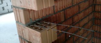
Reinforcement of a monolithic floor. Longitudinal and transverse reinforcement
Concrete works great in compression. The reinforcement is tensile. By combining these two elements we get a composite material. Reinforced concrete, which uses the strengths of each component. Obviously, the reinforcement must be installed in the tensile zone of concrete and absorb tensile forces. Such reinforcement is called longitudinal or working. It must have good adhesion to the concrete, otherwise it will not be able to transfer the load to it. For working reinforcement, periodic profile rods are used. They are designated A-III (according to the old GOST) or A400 (according to the new one).
The distance between reinforcing bars is the reinforcement pitch. For floors it is usually taken equal to 150 or 200 mm. In case of pinching, a supporting moment occurs in the support zone. It generates tensile force in the upper zone. Therefore, working reinforcement in monolithic floors is placed both in the upper and lower zones of concrete. Particular attention should be paid to the lower reinforcement in the center of the slab, and the upper reinforcement at its edges. And also in the area of support on internal, intermediate walls/columns, if any, this is where the greatest stresses arise.
How to calculate formwork for walls?
The main components of the formative structure for walls are panels and load-bearing supports, ties and twists, which act as connecting elements. You can also use steel or aluminum formwork. We offer ready-made systems. To calculate the rental of formwork, enter the initial data into the fields of the calculator.
Let's look at how to calculate the formwork of walls and the volume of concrete mixture for pouring an object. We will need the following parameters:
- width of the wall according to the project;
- object perimeter;
- object height;
- board parameters.
Let's calculate the wall formwork using the example of an object 50 cm thick. In this case, the forming system does not need screeds. Enough shields with strong stiffening ribs. If the wall thickness is over 50 cm, then shields will be required to be fought. To avoid mistakes, we recommend using our calculator for calculating the formwork of monolithic parts of a building. The process boils down to filling in the fields with initial data. You get the result within 2-3 seconds. If you need to calculate wall formwork, use a calculator - reliably, quickly and accurately.
Calculation of a monolithic floor
Initial data
Regardless of the chosen formwork installation method, the same quality result and compliance with dimensions are required. Therefore, there is a set of requirements and calculations that are the same for both methods.
Let's assume that we need to install a monolithic reinforced concrete floor over a rectangular building with an internal load-bearing wall. Internal dimensions of the premises: 5x3.7 m and 5x2.5 m. Ceiling height 2.7 m.
Concrete calculation
The overlap area will be equal to:
- S = 5 x (2.5 + 3.7) + 1 x 0.4 = 31.4 m2
With a thickness of 200 mm, the volume of concrete will be equal to:
- V = 31.4 x 0.2 = 6.28 m3
The mass of the overlap will be equal to:
- M = 6.28 x 2500 = 15700 kg = 15.7 tons
Calculation of reinforcement
To reinforce the floor, an A3 Ø 16 reinforcement frame made of two mirror meshes with a pitch of 180 mm was used. The number of longitudinal rods in one mesh is the width of the overlap divided by the pitch:
- Nprod = 5000 / 180 = 27.7 = 28 pcs.
Length of longitudinal rods in one mesh:
- Lprod = Nprod x A = 28 x 6.6 = 184.8 = 185 m
The number of transverse rods in one mesh is the length of the overlap divided by a step of 180 mm:
- Ntop = 6600 / 180 = 36.6 = 37 pcs.
Length of cross bars in one mesh:
- Ltop = Ntop x B = 37 x 5 = 185 m
Total length of rods in one mesh:
- L1 = Lprod + Ltop = 185 + 185 = 370 m
Total length of rods in the floor frame:
- Ltotal = L1 x 2 = 370 x 2 = 740 m
For 1 m2 of flooring there are 740 / 31.4 = 23.5 linear meters. m of fittings.
For 1 m3 of flooring there are 740 / 6.28 = 117.8 linear meters. m of fittings.
Quantity of plane material
When using plywood to create a table plane, it is necessary to calculate the number of whole sheets (1220x2440 mm, 3 m2), based on the linear dimensions of the premises. This is done to reduce waste:
- N = Spom / Ssheet = 31.4 / 3 = 10.5 pcs.
A total of 10 whole sheets of laminated plywood are needed. The remaining space can be covered with cheaper material - ordinary plywood or board.
If a 100x25 board is taken as the main material of the plane, then its volume will be:
- Vboards = 31.4 x 0.025 = 0.785 m3
Number of inventory beams
The specificity of prefabricated formwork is that it consists of crossbars on which beams rest. The pitch of the crossbars is no more than 1.2 m, they are located along the room. The pitch of the beams is 400–600 mm, and they usually run transversely. The number of support beam lines will be equal to the width of the room divided by the step. In our case:
- N1 = 3.7 / 1.2 = 3.08, take 3
- N2 = 2.5 / 1.2 = 2.08, take 2
In total, there are two lines of crossbars in each room. These are 10 beams of 2.8 m each.
Cross beams are calculated based on the width of the premises. In our case - 10 pcs. 3.6 m each and 10 pcs. 2.4 m each.
Number of racks
Telescopic inventory racks are installed only under crossbars with a pitch of 800–1000 mm. In our case, five lines of 5 meters each - 25 meters. Divide by step and get the quantity:
- Nracks = 25 / 0.8 = 31.25 = 32 pcs.
Each stand has one tripod and one unifork (“crown”).
Advice. Choose racks of maximum height. This will make it easier to mark and set the horizon. The rack should not be extended to the maximum - the more liner in the bar, the stronger it is.